Analysis and Design of Patch Array Antenna By
using Microstrip Feed
Mrs. D. Kalaiarasi 1, A. Asha 2, N. S. Nithiya 3, U. Priyaa4
1, 2, 3, 4
Department of Electronics and Communication Engineering, Panimalar Institute of Technology, Chennai, India.
Abstract: In this a patch array antenna and a slot antenna capable of super high frequency (SHF) operation is designed and analysed. A new patch element is proposed to produce specific polarized radiation efficiently and its characteristics are based on a 2-port network model. Simulation results show that the desirable radiation pattern in a wide frequency band from 5GHZ to 10GHZ. A 1x2 and 2x2 antenna array and slot prototype is designed measured in our laboratory. The return loss and gain parameters are measured for array and slot antenna. The inherent compact size, light weight and good return loss and gain make this array and slot antenna a promising candidate for future communication and advanced sensing systems.
Index Terms: Antenna Arrays, Patch array antenna, Slot antenna, Return loss, Radiation pattern, Gain, Frequency, ADS.
I. INTRODUCTION
There is an increasing demand of super high frequency, low profile, low cost, beam scanning[1]-[5] and low volume antennas. Therefore the array and slot antennas are used to achieve these performances. Based on the concept of array and slot antenna parameters are compared with the substrates like FR_4 and RT_Duroid 5880. These elements are properly coupled and fed by the Microstrip feed[8]. The input electromagnetic power can be efficiently transferred between the feed port and the space. The parameters like return loss and gain are compared with the substrates such as FR-4 [7] and RT_Duroid 5880 [6] for array and slot antenna. To realize an effective transform from 50 to 377 ohm, some novel patch arrays[3] were developed.
In this paper the operation bandwidth of a new microstrip feed patch array and slot antenna[9],[10]. An element composed of a pair of patches is proposed, and its characteristics are analysed by using an equivalent network and a unit cell model. To validate the design methodology, a 1x2 and 2x2 array and slot prototype is designed and measured.
II. ELEMENT ANALYSIS AND DESIGN
A. Analysis Methods
Fig.1 2x2 Patch array antenna
Fig.2 a) Equivalent 2-port network model and its scattering matrix.S11 and Ss22 are reflection coefficients. S12 and S21 are
Fig.1 shows the 2x2 patch array antenna. A Patch array antenna is a type of radio antenna with a low profile, which can be mounted on a flat surface. It consists of a rectangular sheet or patch of metal, mounted over a larger sheet of metal called a ground plane. As shown in fig.1, the proposed patch array antenna consists of a slab formed by periodic sub wavelength patches, each of which is excited by a feed and backed with a metallic reflector for unidirectional radiation. Basically, since an antenna can be regarded as a device transferring electromagnetic energy between the electric circuit and the free space, it can be modelled by a two-port network connecting the free space (port 1) and the feed line (port 2) as depicted in Fig. 2(a). Note that the maximum antenna efficiency is only achieved when the antenna impedances Z1 and Z2 are matched to those of the two ports characterized by the free-space impedance (377 ohms) and the typical coaxial line characteristics impedance (50 ohms), respectively. From this viewpoint, an ideal antenna can be represented by a 2x2 scattering matrix with minimum reflection (│S11│ =│S22│=0) and maximum transmission
coefficients (│S12│ =│S22│=1). This general network model can be useful for designing a highly efficient element subsequently.
According to Floquet theory[11],[12], the problem of an infinite array made of coupled periodic elements can be accurately solved by using a unit cell surrounded by periodic boundaries and Floquet port as sources.Fig.2(b) illustrate the way to build such a unit cell model. Floquet port (port 1) and lumped port (port2) are applied to the top face of the air cavity and element centre, respectively. An observation plane is said to observe the surface impedance at different heights by changing the de-embed distance. Note that, in the old design procedure, the observation plane is placed on the interface between the patch and free space .Based on this unit cell model, scattering parameter of a two port equivalent network can be simulated for different Floquet modes. Since the high Floquet modes are evanescent waves in the z direction according to our investigation, only the lowest modes (TE00 OR TE00)
results are considered. The load impedance supposed to be 50 ohms here for a typical coaxial cable case, but can be changed to any value according to the practical feed lines.
B. Element Design
Fig.3 Geometry of the proposed element
1) Top view of proposed element with feed and
2) Its side view
As depicted in Fig. 3, the original element is composed of a pair of rectangular patches printed on a substrate of size L × W. The length of the rectangular patch is Ld and space between them is Ws. This element can also be viewed as a patch of size Ld × W d and is centrally cut into two pieces with a horizontal slit with a width of Ws. The distance between the substrate and the backed metallic reflector is H. In practice, the patch is printed on a substrate with a thickness of 1.6 mm and a permittivity of 2.65, which can be seen in Fig. 3(b). Full-wave analysis based on the proposed unit cell model is performed to demonstrate the current distributions on the element. The result shown in Fig. 3(a) confirms the vertical polarization (aligned to the y-axis) in the broadside direction.
a) Substrate: In this two substrates are compared
i) FR_4, 2) RT_Duroid 5880.
b) FR_4: FR_4 stands for flame retardant, and denotes that the material complies with the standard UL94V-0.In 1968 the designation FR-4 was created by NEMA .
c) RT_Duroid 5880: RT_ Duroid 5880 glass microfiber reinforced PTFE composite is designed for exacting stripline and microstrip circuit applications. Glass reinforcing microfibers are randomly oriented to maximize benefits of fibre reinforcement in the directions most valuable to circuit producers. The dielectric constant of RT_Duroid 5880 laminates is uniform from panel to panel and it is constant over a wide frequency range. Its low dissipation factor extends the usefulness of RT_Duroid 5880. Lamination of RT_Duroid 5880 is easily cut, sheared and machined to shape. It has excellent dimensional stability and is resistant to all solvents and reagents, normally used in etching printed circuits.
III. ANTENNA IMPLEMENT
A. Practical Feeding
The array element under investigation is excited using an ideal lumped port in the above analysis. In practice, the lumped port should be replaced by a realizable feed structure, which is connected to the coaxial line. As described in Fig. 4(a)–(c), the practical
feed structure is formed by using a microstrip line terminated by a radial stub with a radius of R and angle θ. The microstrip line is
printed on the top side of a substrate for easy soldering with the inner conductor of the coaxial line. The rectangular patches are printed on the bottom side of the substrate, and one of them is connected with the outer conductor of the coaxial line. Furthermore, there is a small circular hole on the reflector so that the coaxial line can easily go through and is connected to an external source. The dimensions and the position of the practical feed structure are carefully adjusted to minimize the input reflection. The optimized element parameters are showed in the below table.
Length of the patch 13 mm Width of the patch 2 mm Thickness of the
substrate
1.6 mm
Radius 10 mm
Radius of the slot 5 mm
(c)
1) Microstrip feed: Microstrip antennas are excited for radiation modes using different techniques which lead to best impedance matching between the feed line and the patch. This paper describes the technique which use microstrip line for a patch array antenna.
B. Excitation Pattern
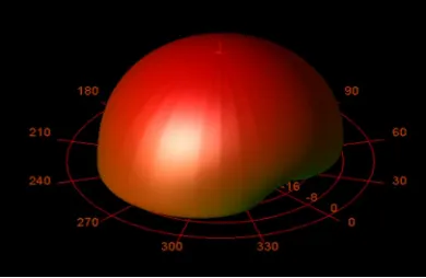
To demonstrate the feasibility of the proposed patch array antenna, a finite 1x2, 2x2 array prototype was designed and measured. In the field of designing an antenna the term radiation pattern refers to the directional variation in intensity of the radiation from the source. In the fields of fiber optics and integrated optics, the term radiation pattern also be used as a synonym for the near-field .This refers to the positional dependence of the electromagnetic field in the near-field of the source. The near-field pattern is defined over a plane placed in front of the source, or over a cylindrical or spherical surface enclosing it.
Fig. 5a) Radiation pattern for 2x2 array antenna
Fig. 5b) Radiation pattern for 2x2 slot antenna
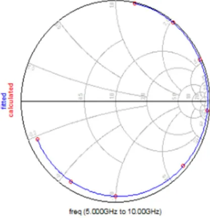
IV. SIMULATION RESULT & DISCUSSION
The proposed antennas are simulated by ADS software.
[image:4.612.209.404.209.336.2]The below figures shows the graph for 1x2, 2x2 array and slot antenna
Fig. 6a) Frequency versus Magnitude of 1x2 array antenna
[image:5.612.198.406.470.686.2]Fig.7a) Frequency versus Magnitude of 2x2 array antenna
Fig.7b) Normalized radiation pattern for 2x2 array antenna
Fig. 8a) Frequency versus Magnitude of 1x2 slot antenna
Fig. 9a) Frequency versus Magnitude of 2x2 slot antenna
Fig.9b) Normalized radiation pattern for 2x2 slot antenna
V. CONCLUSION
A patch array antenna is developed and valued in this paper. General design methodology is presented by element design, optimization, realization and measurement. Frequency ranges from 5GHZ to 10GHZ were the super high frequency is obtained. A 1x2 and 2x2 array and slot prototype is designed and measured to validate the design methods. As the result of comparison between array antenna and slot antenna, RT_Duroid 5880 substrate for 2x2 in slot antenna has better gain comparatively.
REFERENCES
[1] B. A.Munk, Finite Antenna Arrays and FSS. Hoboken, NJ, USA: Wiley, 2003.
[2] J. L. Volakis and K. Sertel, “Narrowband and wideband metamaterial antennas based on degenerate band edge and magnetic photonic crystals,” Proc. IEEE, vol. 99, no. 10, pp. 1732–1745, Oct. 2011.
[3] A. Neto, D. Cavallo, G. Gerini, and G. Toso, “Scanning performances of wideband connected arrays in the presence of a backing reflector,” IEEE Trans. Antennas Propag., vol. 57, no. 10, pp. 3092–3102, Oct. 2009.
[4] I. Tzanidis, K. Sertel, and J. L. Volakis, “UWB low-profile tightly coupled dipole array with integrated balun and edge terminations,” IEEE Trans. Antenna Propag., vol. 61, no. 6, pp. 3017–3025, Jun. 2013.
[5] J. P. Doane, K. Sertel, and J. L. Volakis, “A wideband, wide scanning tightly coupled dipole array with integrated balun (TCDA-IB),” IEEE Trans. Antennas Propag., vol. 61, no. 9, pp. 4538–4548, Sep. 2013.
[6] Bondili.KohithaBai,Govarthini.Immadi,”Design of Rectangular Microstrip Array Antenna For KA-Band Applications,”vol.117, No 18,2017,127-133 [7] Xi Yang,Pei-Yang ,Qin,Ying-Zeng Yin,”Analysis and Design of a Broadband Multifeed Tightly Coupled Patch Array Antenna,”vol.17,No.2,Feb 2018. [8] Roshini.S.Babu,P.Sampath,”Design Of 4*4 Rectangular Microstrip Phased Array Antenna For GSM Application,”Vol.1.Issue 4:Page no
403-407,November-December(2012).
[9] W. Liu, Z. N. Chen, and X. Qing, “Metamaterial-based low-profile broadband aperture-coupled grid-slotted patch antenna,” IEEE Trans. Antennas Propag., vol. 63, no. 7, pp. 3325–3329, Jul. 2015.
[10] F. H. Lin and Z. N. Chen, “Low-profile wideband metasurface antennas using characteristic mode analysis,” IEEE Trans. Antennas Propag., vol. 65, no. 4, pp. 1706–1713, Apr. 2017.
[11] F. R. Yang, K. P. Ma, Y. Qian, and T. Itoh, “A uniplanar compact photonicbandgap (UC-PBG) structure and its applications for microwave circuit,” IEEE Trans. Microw. Theory Techn., vol. 47, no. 8, pp. 1509–1514, Aug. 1999.