Improving Direct Torque Control of Induction
Motor with Dither Injection
N. O. Ogbogu1, Okoye Akachukwu H2
1
Electrical/ Electronic Engineering, University of Port Harcourt, Rivers state
2
University Of Port Harcourt, Rivers State
Abstract: Director torque control (DTC) is a well-known scheme for induction motor drives. It is characterized by variable inverter switching frequency, high torque ripples and high sampling requirement due to delay in the system. A triangular wave is used as dither injection signal in order to minimize the impacts of flux and torque ripples in a three-level inverter-fed induction motor drive. This in essence does not impact on the dynamic performance of the system. When the system is on free running condition, it will enable estimation of optimum value of dither frequency and magnitude. It is expected that the proposed technique would reduce the impact of torque ripples by about 60% when compared with the case without dither injection technique. The propose technique will also reduce acoustic noise and increase switching frequency of inverter. DTC induction should not be used under low speed region, otherwise, it would result in poor performance which is caused by stator flux demagnetization that varies with resistance.
Keywords: Direct torque control, dither injection, induction motor drives, switching frequency, ripple current, Voltage source inverter.
I. INTRODUCTION
Induction motors are integral to functionality of any industrial activities. According to Mankad & Chudasama (2014), three phase induction motor constitutes over 70% of motors used in the industry. Their popularity is tied to their robustness, simple construction and maintenance free operation. Induction motor has been applied for decades for motive power with variable speed due to its simple control. However, complex structure associated with induction motor makes it unsuitable for variable frequency operation. So many advancement has been made to reduce the complexity of three phase induction motor and give good dynamic response to induction motor drive, and one of such improvement is the direct torque control scheme. This scheme uses one vector voltage out of six active and zero voltages vectors generated by voltage source inverter (VSI). The selection is so done that the torque and stator flux remain limits of hysteresis band. Application of this strategy resulted in decoupled control of induction motor with engaging in complex co-ordinate transformation, current regulators or pulse width modulation (PWM) pulses. However, due to hysteresis band controller for torque and stator flux, there is a production of ripples in torque and stator current, as well as variable switching frequency. This problem becomes significant at low speed and heavy load. Although various technologies have invented that have shown positive impact in addressing these issues. Dither injection technique is the focus of this research. Ranjan and shyama (2011) presented three level neutral point inverter as playing significant role in the working principle of direct torque control strategy. it is shown that drive’s efficiency is improved without being affected during low switching frequency operation. According to the researcher, measurement and computational delay would lead to low switching frequency, which invariably increase torque and flux ripples. Study conducted by Sirisha and Nireekshan (2017) showed that enhanced performance of direct torque control scheme led to its replacement of field Oriented control scheme in 1980’s. in DTC algorithm, the author stated that torque and flux are controlled independently, hence in order to satisfy their demands, there is need to suitable vector according to the digitized status produced from the hysteresis controller. However, the researcher identified two basic problems with direct torque controller in spite of its simplicity: variable switching frequency and large torque ripples.
A. Features of Direct Torque Control
In this method, it is possible to control directly the stator flux and the torque by selecting the appropriate inverter state.
1) Its main features are as follows:
a) Both torque and stator are controlled directly.
b) Currents and voltages are controlled indirectly
c) Approximately sinusoidal stator fluxes and stator currents
International Journal for Research in Applied Science & Engineering Technology (IJRASET)
ISSN: 2321-9653; IC Value: 45.98; SJ Impact Factor: 7.177 Volume 7 Issue XII, Dec 2019- Available at www.ijraset.com
2) The aforementioned presents the following advantages
a) There is no co-ordinate transform
b) There is no voltage co-ordinate block and other controllers
c) Vector time is minimal
3) Disadvantages present are:
a) Possible problem during starting
b) Requirement of torque and flux estimator, implying the consequent parameters identification
c) Inherent torque and flux ripples
[image:2.612.90.526.199.435.2]II. DIRECT TORQUE ALGORITHM
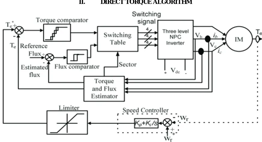
Fig 1: Block Diagram of Three Level Inverter-fed DTC Induction Motor Drive
Fig 1 shows a diagram in which three level voltage source inverter feed induction motor drive, which involves two hysteresis band controller. DTC is a scheme that deals so much on stator flux whose principle is characterized by limiting the cycle of both rotor and stator flux. Stator flux controller determines the time duration of the active voltage vectors, which moves the stator flux along the point of reference. Zero voltage vector, which relates to torque controller which ensures that motor torque is sustained within the specific hysteresis band. The inverter switching state is chosen by the selection block at every sampling time to reduce instantaneous flux and torque error.
III. DITHER SIGNAL INJECTION
In order to address the challenges confronting direct torque control induction motor, dither injection strategy is one of the techniques adopted. Due to the presence of torque and ripple flux caused by delays in measurement and computation, dither signal injection technique is used to reduce the effect. (LV 25-P) is the choice of sensor used to measure voltage whereas (LA-55-P) is used for current measurement. When there is sensor response time, it leads to delay. For multiplex channel, analogue to digital (A/D) conversion time is 2µs and for multiplex channel and 800 ns for parallel channel. Time required to execute the estimator is 1.66µs. Average time delay for DTC drive is 7.5µs.
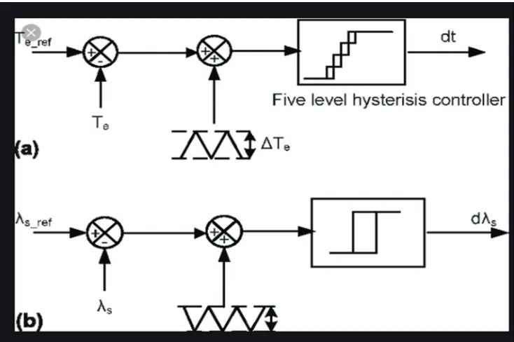
Fig 2(a): injection of triangular dither in torque control loop; (b) injection of triangular dither in flux control loop.
Activities of the hysteresis band for the torque control affect the inverter switching frequency. It is observed that only one leg of the three phases of the inverter changes its own switching state at every switching time of the hysteresis element as operation of relay performs between alternately between a zero voltage vector and a non-zero voltage vector. element. With this, switching frequency of the inverter can be approximated to one-sixth of the dither frequency for three level NPC inverter fed of the induction motor drive. Condition of flux and torque error command influences selection of applied voltage vector in convention switching algorithm. Delay in the feedback system causes the torque and flux error to cross boundary of error band limit.
IV. ANALYSIS AND COMPARISON OF RESULTS
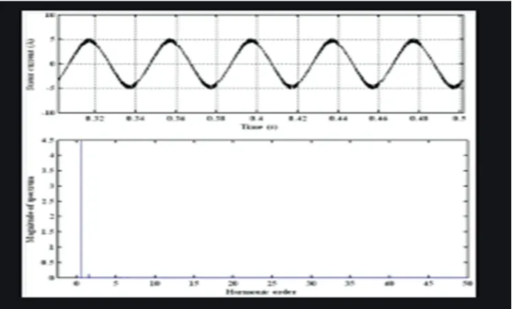
[image:3.612.123.490.76.320.2]Table 1 gives induction motor drive parameters in terms of rated values and nominal voltage. Simulation was carried out using Matlab-Simulink software. Results of simulation are presented in fig 4.2 and 4.3. these simulation results carried out under rated flux condition, were obtained when induction motor was driven at 1000 rpm under the free running condition. All results were carried out with and without triangular dither injection for comparison. Triangular dither is injected here having a 30Khz frequency. Amplitude of dither signal is 5% of rated torque and the amplitude of the dither signal in flux control loop is 5% of reference flux. Both the dither signal is opposite to each other in phase to minimize the acoustic noise.
Table 4.1: Induction motor drive ratings and parameters
DC link capacitor c1=c2 2200µF
Power 5hp
Voltage (L-L) 415V
Current 7.6A
Frequency 50Hz
Rated torque 24.5N-m
speed 1440rmp
Stator Resistance (Rs) 2.177Ω
Rotor Resistance (Rr) 1.275Ω
Stator Leakage Inductance (LIs) 0.0081H
Rotor Leakage Inductance (LIs) 0.0081H
[image:3.612.181.433.549.727.2]International Journal for Research in Applied Science & Engineering Technology (IJRASET)
ISSN: 2321-9653; IC Value: 45.98; SJ Impact Factor: 7.177 Volume 7 Issue XII, Dec 2019- Available at www.ijraset.com
[image:4.612.132.482.95.360.2]A. Improved Direct Torque Control of Induction Motor with Dither Injection
[image:4.612.120.495.398.624.2]Fig 3: Steady State Stator Current and Harmonic Spectrum without Dither Injection
Fig 4: steady state stator current and harmonic spectrum with dither injection
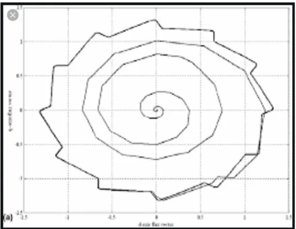
Fig 5: stator flux trajectory without dither injection
Fig 6: stator flux trajectory with dither injection
V. SUMMARY
For decades, direct torque control induction motors gained popularity due to their robustness, simple construction and maintenance free operation. However, complex structure associated with induction motor makes it unsuitable for variable frequency operation. So many advancement has been made to reduce the complexity of three phase induction motor and give good dynamic response to induction motor drive, and one of such improvement is the direct torque control strategy, and finally dither injection method was used to improve the system by minimizing torque current ripple.
VI. CONCLUSION
Although direct torque control offers robustness, simple construction and maintenance free operation, yet improvement using dither injection method makes the motor more functional and better in usefulness.
VII. RECOMMENDATION
[image:5.612.157.460.349.531.2]International Journal for Research in Applied Science & Engineering Technology (IJRASET)
ISSN: 2321-9653; IC Value: 45.98; SJ Impact Factor: 7.177 Volume 7 Issue XII, Dec 2019- Available at www.ijraset.com
REFRENCES
[1] Alnasir, Z. A. &Almarhoon, A. H. (2012). Design of Direct Torque Controller Induction Motor (DTC). International Journal of Engineering and Technology (IJET). Vol. 2, No. 2, April.
[2] Behera, R. K., & Das, S. P., (2008). Improved Direct Torque of Induction Motor with Dither Injection. https/www.researchgate.net/publication/226139924. [3] Kadjoudj, M., Taibi, S., Golea, N., Benbouzid, M.E.H (2015). Modified Direct Torque Control of PMSM Drive Using Dither Injection Signal and
Non-Hysteresis Controller. Electromotion International Journal 13 (4) pp. 262-270
[4] Kumar Vinay & Rao Srinivasa (2011). Modified Direct Torque Control of Three Phase Induction Motor Drives with Low Ripple in Flux and Torque. Leonardo Journal of Sciences, Issue 18, PP. 27-44, ISSN: 1583-0233, January
[5] Mankad, P. R. &Chudasama, A. R. (2014). Review of Improved Direct Torque Methodologies for Induction Motor Drive. International Journal of Innovative Research in Advanced Engineering (IJIRAE), Vol. 1, Issue 6, ISSN: 2349-2163, July
[6] Ranjan Kumar Bethera&Shyama, P. Das (2011). High Performance Induction Motor Drive: A Dither Injection Technique. International Conference on Energy Automation and Signal.
[7] Saravanan, S. &Geetha, K (2014). Direct Torque Control of Induction Motor Drive- A Study. Australian Journal of Basic and Applied Sciences, 8(1), pp. 213-221, January.