A Non Isolated Buck Boost Converter using Fuzzy
Logic Controller
Dhavala Pranusha1, R. Nageswara Rao2
1, 2
M.Tech, Dept of EEE, G. Narayanamma Institute of Technology and Science
Abstract: The buck boost converter is a dc-dc converter which produces output voltage that is either greater or less than that of input voltage magnitude. A buck boost converter is used in many industrial applications, fuel cells and photovoltaic cells. Due to global warming use of clean form of energy sources like fuel cells and photovoltaic cells has increased rapidly in the past few decades. As both the sources are low voltage sources there is a need to boost the voltage.
Traditional buck boost converter has disadvantages such as limited voltage gain, discontinuous and continuous output currents. To overcome the above mentioned disadvantages a non-isolated buck boost converter came into existence. The operational modes of the converter are presented.In this paper the output results of the PI controller and fuzzy logic controller are compared. Keywords: Buck Boost Converter, Non isolated buck boost converter, Fuel cells, Photovoltaic cells, Voltage gain
I. INTRODUCTION
The buck boost converter is a dc-dc converter in which produced output voltage is either greater or less than that of the input voltage magnitude. The converter is nothing but a fly-back converter using an inductor instead of a transformer. When the switch is on, the inductor absorbs the energy from the source. When the switch is in off mode the inductor supplies the energy to the load. If the size of the inductor is large the output current of the converter will be continuous. The efficiency of the buck boost converter is very high
compared to buck and boost converters.
Fig.1. Conventional Buck Boost Converter
The buck boost converters are mainly employed in fuel cells, photovoltaic cells, battery power systems and many more. With the increase in pollution global warming and green house effect have become burning issues. In order to reduce carbon dioxide emissions clean form of energy is to be produced. Photovoltaic cells and fuel cells provide clean form of energy. Fuel cells and photovoltaic cells come under the category of low voltage sources.The output of the fuel cells unit is not steady and for applications that need a steady output voltage a buck boost converter is employed.
Theoretically boost and buck boost converters can be employed to produce high voltage gain but usage of conventional buck boost converter is limited by discontinuous input and output currents and not so expected high efficiency. So non-isolated buck boost converters came into existence. A Non isolated circuit does not employ a transformer as an isolated circuit. This reduces the size of the circuit and switching losses when compared with the isolated circuit.
II. NON ISOLATED BUCK BOOST CONVERTER
Fig.2.NON Isolated Buck Boost Converter
A. Continuous Conduction Mode
First mode (0 ≤ t≤ DTs) : During this time interval the switch is turned on, all the three diodes are reverse biased. The inductors L1,
L2 and L3 are charged linearly. The capacitors are charged by C1 and C4 are charged by the capacitors C2 and C3.
FIG.3.Mode1
Second mode (DTs ≤ t ≤ T): The equivalent circuit is shown in figure 4.During this interval the switch is turned off. The diodes D1, D2 and D3 are forward biased. The inductors L1, L2 and L3 are demagnetised linearly. The capacitor C2 is charged by the inductor L1 and the capacitor C3 are charged by the inductor L1 and L2. The energy stored by the capacitors C3 and C4 is discharged.
FIG.4.Mode 2
B. Discontinuous Conduction Mode
III. FUZZYLOGICCONTROLLER
A fuzzy controller which works based on fuzzy logic that analyses analog input values in terms of logical variables. Fuzzy logic idea is similar to the inference process and human being feeling. In classical control strategy there is point to point control where as in fuzzy logic control there is range to point or range to range control. Fuzzy controllers are used to control consumer electronics such as video camera, washing machines etc. These controllers are also used in many industrial processes.
Fig.5. Block Diagram of Fuzzy Logic Controller
Fuzzy ideas and fuzzy logic are frequently utilised by human beings in daily routine without our knowledge. For example to rate the product there will be few options like very satisfied and not satisfied which are fuzzy answers. To what extent an individual is satisfied or dissatisfied over the product depends solely on him. These kind of answers are created and implemented by only human beings. Computers cannot answers these kind of questions in surveys. They can only understand machine language ‘0’or ‘1’ and “high” or “low”. Those data are called crisp data which is processed by all machine.
Fuzzification is a process in which the crisp data is converted into membership functions. Two membership functions namely input 1 and input 2 are combined to produce membership function output 1. The inputs variables in membership function input 1 are NB, NS, ZE, mf4 and PB respectively. The input variables in membership function input 2 are NB, NS, ZE, PS and PB respectively. The input variables NB and PB are trapezoidal waveforms. The input variables NS, ZE and mf4 are triangular shaped waveform
Fig.6. Membership Function of Input Variable 1
Fig.8.Membership Function of Output Variable Output 1
Fuzzy inference process combines membership functions with the control rules to derive the fuzzy output. The control rule is the core of fuzzy inference process. It is similar to human intuition or feeling. For example in air conditioner control if the temperature is too high the heater must be turned off. Different methods such as centre of gravity or maximum of mean are used to calculate the associated output. The obtained output must be arranged in a table called look up table.
Fig.9.Fuzzy Logic Tool Box
Defuzzification uses different methods to calculate each associated output and put them into a look up table. It picks up the output from the look up table based on the current input associated with the input. The control output should be converted from the linguistic variable back to the crisp variable and output to the control operator.Fuzzy control rule can be considered as the knowledge of an expert in the field of any related application. The fuzzy rules are representated by a sequence of the form if- then. This leads to algorithms describing what action should be taken in terms of currently observed information. To build a set of rules it depends on human being’s experience which is dependent on each different application.The rules are discussed in table 1.
TABLEI Input2
Input1
NB NB ZE PS PB
NB NB NB NB NS ZE
NS NB NB NS ZE PS
ZE NB NS ZE PS PB
mf4 NS ZE PS PB PB
IV. SIMULATION OF THE CONVERTER USING PI CONTROLLER
Fig.10. Simulink Diagram of the Converter using PI Controller
The dc filter filters out the ripples present in the output. The reference values are given in the stair generator. The stair generator is actually used to check out the error with voltage in specific time periods. The dc filter and stair generator are connected to the summing point. The output of the controller and repeating sequence input are given to the relational operator. When the output of the carrier waveform is more than the reference waveform a pulse is generated. Otherwise no pulse is generated. The output of the relational operator is given to the go to block. From the go to block pulses signal will go to the pulse generator.
The specifications of the components used in the converter are mentioned below:
1) Inductor L1(buck): 1 mH;
2) Inductors L1 and L2(Buck): 580µH;
3) Inductor L1(Boost): 100µH;
4) Inductors L2 and L3(Boost): 260µH;
5) Capacitors C1,C2,C3 and C4: 100µF;
A. Buck Mode Waveforms
In this mode input voltage applied at the source is 11V. The output voltage obtained is 6v. Dc output voltage initially rises with a steep and then settles down as shown in the figure below.
Fig.11. Output Voltage Waveform
In the figure 12 shown below the inductor current has transient till 0.12 sec. The peak transient current is given by the value 48 A.
Fig.12.Current Waveform of Inductor IL1
In the figure 13 shown below the inductor current has transient till 0.125 sec. The peak transient current is given by the value 16 A.
In the figure 14 shown below the inductor current has transient till 0.125 sec. The peak transient current is given by the value 16 A.
Fig.14. Current Waveform of Inductor IL3
B. Boost Mode Waveforms
In this mode the output voltage obtained is 30v. The settling time obtained from the figure 15 is 0.039s.
Fig.15. Output Voltage Waveform
In the figure 16 shown below the inductor current has transient till 0.02 s. The peak transient inductor current is given by the value 102 A.
In the figure 17 shown below the inductor current has transient till 0.02 s. The peak transient current is given by the value 12.9 A. During constant reference voltage and constant output voltage inductor current will be nearly constant as shown at t=0.02 s because there is no change in output voltage.
Fig.17. Current Waveform of Inductor IL2
In the fig 18 shown below the inductor current has transient till 0.02 s. The peak transient current is given by the value 11.9 A
Fig.18. Current Waveform of Inductor IL3 C. Buck Boost Waveforms
In the figure20 shown below the inductor current has transient till 0.12 s. The peak transient current is given by the value 102 A.
Fig.20. Current Waveform of Inductor IL1
In the figure 21 shown below the inductor current has transient till 0.12 s. The peak transient current is given by the value 11.8 A.
Fig.21.Current Waveform of IL2
In the figure 22 shown below the inductor current has transient till 0.12s. The peak transient current is given by the value 9.9 A.
V. SIMULATIONOFTHECONVERTERUSINGFUZZYLOGICCONTROLLER
Fig.23. Simulink diagram of the Converter using Fuzzy Logic Controller
A. Buck Mode Waveforms
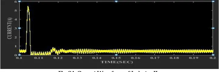
In this mode the output voltage obtained is 6V. In the figure 24 shown below the settling time is 0.11 s.
In the figure shown 25 below the inductor current has transient till 0.115 sec. The peak transient current is 10 A.
Fig.25. Current Waveform of Inductor IL1
In the figure 26 shown below the inductor current has transient till 0.115 s. The peak transient current is 5 A.
Fig.26. Current Waveform of Inductor IL2
In the figure 27 shown below the inductor current has transient till 0.11 s. The peak transient current is 5 A.
B. Boost Mode Waveforms
In this mode output voltage obtained is 30 V. From the fig28 the setting time obtained is 0.013 s.
Fig.28. Output Voltage Waveform
In the figure 29 shown below the inductor current has transient till 0.105 s. The peak transient current is 13 A.
Fig.29. Current Waveform of Inductor IL1
In the figure 30 shown below the inductor current has transient till 0.105 s. The peak transient current is 5.8 A.
In the figure 31 shown below the inductor has transient till 0.105 s. The peak transient current obtained is 5 A.
Fig.31. Current Waveform of Inductor IL3
C. Buck Boost Mode Waveforms
In this mode output voltage obtained is 31 V. In the figure 32 shown below the settling time obtained is 0.015 s.
Fig.32. Output Voltage Waveform
In the figure 33 shown below the inductor has transient till 0.11s. The peak transient current given is 14.6 A.
In the figure 34 shown below the inductor has transient till 0.11 s. The peak transient current is 5.5 A.
Fig.34. Current Waveform of Inductor IL2
[image:14.612.112.495.244.379.2]In the figure 35 shown below the inductor current has transient till 0.109 s. The peak transient current is 4.9 A.
Fig.35. Current Waveform of Inductor IL3
[image:14.612.75.541.434.492.2]VI. COMPARISONS
Table 2 Settling Time Comparsion
Modes of Operation PI Controller Fuzzy Controller
BUCK 0.132 s 0.11s
BOOST 0.039 s 0.013s
BUCK BOOST 0.14 s 0.015s
Table 3 Peak Transient Currents of Inductors in Buck Mode
Buck mode PI controller Fuzzy Controller
Inductor current IL1 48 A 10 A
Inductor current IL2 16 A 5 A
Inductor current IL3 16 A 5 A
Table 4 Peak Transient Currents of Inductors in Boost Mode
BOOST MODE PI Controller Fuzzy Controller
Inductor current IL1 102 A 13 A
Inductor current IL2 13.5 A 5.6 A
Inductor current IL3 11.9 A 5 A
Table 5 Peak Transient Currents of Inductors in Buck Boost Mode
BUCK BOOST MODE PI Controller Fuzzy Controller
Inductor current IL1 102 A 14.6 A
Inductor current IL2 11.8 A 5.5 A
VII. CONCLUSIONS
A non-isolated buck boost converter is operated in three modes namely buck, boost and buck boost. The converter is simulated using PI and fuzzy logic controllers. The corresponding results are compared in the above tables. For example in buck boost mode the settling time using pi controller is 0.14 sec whereas by using fuzzy logic controller the settling time is 0.015 sec. The peak transient current of inductors are reduced by using fuzzy logic controller when compared to Pi controller. Even the settling time is reduced by using fuzzy logic controller.
REFERENCES
[1] O. Abutbul, A. Gherlitz, Y. Berkovich, and A. Ioinovici, “Step-up switching-mode converter with high voltage gain using a switched-capacitor circuit.” IEEE Trans. Circuits Syst. I, Fundam. Theory Appl., vol. 50, no. 8, pp. 1098–1102, Aug. 2003.
[2] K. I. Hwu and W.Z. Jiang, “Isolated step-up converter based on fly-back converter and charge pumps,” IET Power Electron., vol. 7, no. 9,2250–2257, Sep. 2014.
[3] S. C. Tan et al., “Switched-capacitor converter configuration with low EMI emission obtained by interleaving and its large-signal modelling,” in Proc. IEEE Int. Symp. Circuits Syst., May 2009, pp. 1081–1084.
[4] Y. P. Hsieh, J. F. Chen, L. S. Yang, C. Y. Wu, and W. S. Liu, “High-conversion-ratio bidirectional dc–dc converter with coupled inductor,” IEEE Trans. Ind. Electron., vol. 61, no. 1, pp. 210–222, Jan. 2014.
[5] T.-J. Liang and J.-H. Lee, “Novel-high-conversion-ratio high efficiency isolated bidirectional DC-DC converter,” IEEE Trans. Ind. Electron., vol. 62 , no. 7 , pp. 4492–4503, Jul. 2015.
[6] C. T. Pan, C. F. Chuang, and C. C. Chu, “A novel transformerless interleaved high step-down conversion ratio DC-DC converter with low switch voltage stress,” IEEE Trans. Ind. Electron., vol. 61 , no. 10 , pp. 5290–5299, Oct. 2014.
[7] L. S. Yang, T. J. Liang, and J. F. Chen, “Transformer-less DC–DC con-verter with high voltage gain,” IEEE Trans. Ind. Electron., vol. 56, no. 8,3144–3152, Aug. 2009.
[8] K. I. Hwu and T. J. Peng, “A novel buck boost converter combining KY and buck converters,” IEEE Trans. Power Electron., vol. 27, no. 5,2236–2241, May 2012.
[9] 9)A. Ajami, H. Ardi, and A. Farakhor, “Design, analysis and implementation of a buck–boost DC/DC converter,” IET Power Electron., vol. 7, no. 12, 2902– 2913, Dec. 2014.