Abstract—The disassembly process is a process that is time consuming and tasking, the automation of this process will save time and energy thereby making such resources available for other endeavours. This paper discusses the automation of model generation of the CAD assembly from which the transition matrix showing the connections between components are computed. The project relied mostly on the use of various CAD software in producing simple assemblies through which models were generated. The models formed the basis for the generation of the transition matrices. The transition matrix is computed based on joints existing between components. The joints linking the parts allow for restricted movement of these parts and can be used to predict the movement of each component part.
Index Terms—CAD-Assembly, Disassembly-Sequence, Transition – Matrix.
I. INTRODUCTION
he complexity of disassembly process increases as the number of components of the product increase. Manual assembly sequence generation becomes cumbersome calling for the need to find ways to make it easier. Reference [25] highlights the need for computer aided disassembly in the following areas; (i) searching optimized solutions among all the possible alternatives (ii) enhancing product design from a disassembly point of view by implementing the following procedures into CAD tools; interfacing with other computer-aided tools, such as scheduling, simulation and interacting with disassembly plant control units or sensing devices. This work is based on related works that have been done previously [1] – [2], [4], [7] - [8], [10] – [16], [18], [20] – [21], [26]. Some of these works have also shown that automating the product redesign task with recovery value, disassembly, and design modification algorithms may improve product recyclability [34]. Sensitivity analysis is needed for design evaluations since demanufacturing choices may change based on (i) product condition (ii) the development of new automated demanufacturing technologies (iii) commodity market fluctuations (iv) reverse logistics network design.
Currently, third-party demanufacturers do not receive product design information from other entities in the product supply chain. A product environmental profile may include product structure, fasteners, material content and
Manuscript submitted February 06, 2013; revised February 28, 2013.
O. E. Simolowo is a Senior Lecturer in the Department of Mechanical Engineering University of Ibadan Nigeria (phone: +2348059541882; e-mail: esimmar@ yahoo.com).
Onovughe, E. Chinedu is a graduate student at the department of
environmental attributes. Product design information to support computer integrated demanufacturing may be centralized in a company database or decentralized in a product life cycle unit that acquires and stores information throughout the product life cycle [33]. Centralized product information management requires links between reverse supply chain entities. Product design data may aid demanufacturing planning for reuse and recycling [30], [27] – [28], [32]. A significant challenge in computer integrated demanufacturing is obtaining information about the product design and the current state of the recycling network. Product disposition decisions in computer integrated demanufacturing require assessment of the product structure and materials, the current location and quantity of inventory, and the status of operating capacity of the demanufacturing facility(s). Product knowledge may be acquired through a product information system [29], [32].
The problem of generating the disassembly sequences from assembly drawings has initially been addressed by construction engineers aimed at the investigation of assembly processes. It was still assumed that ‘the sequence of assembly is the reverse of that of disassembly’. There was an emphasis on the classification of connection types and fasteners (pressure, screw, etc). Sequences were determined via a heuristic process of modularity analysis based on the study of connections. The first author who elaborated the disassembly process by a comprehensive and systematic method was [6]. His work has been considered ‘alone in outlining the generation of all assembly sequences by algorithmic means’ [9]. He introduced mathematical tools such as set theory, combinatorial analysis, Boolean algebra, and graph theory to the assembly/disassembly problem. References [6] employed the use of connections or precedence relations. Precedence relations are constraints that govern the order of possible disassembly actions. Reference [9] further extended the work of [3] by applying it to sequence generation. According to their method, the set of disassembly choice diagrams is condensed in a single disassembly graph that is based on connective states. These are represented by a set of binary variables. Such a variable is true if the corresponding connection is established. Actions are transitions between these states. Equivalent to connective states, subassembly states can be defined. This idea has been further elaborated [5]. Those authors present an algorithm for automatically deriving a set of precedence relations, supported by queries put to an operator, which could be answered with ‘yes’ or ‘no’. To this purpose, the cut-set method has been developed. Cut-sets are separations from a parent subassembly in two child subassemblies. Among the different weights the time of disassembly tasks,
Automation of Generation of Models for
Disassembly Process Planning for Recycling
Simolowo O. Emmanuel, Member, IAENG, and
Onovughe, E. Chinedu
the necessity to fix the assembly on supports, the cost of recycled materials and the importance of the different parts reuse are considered [7] , [19]. Other works have addressed the disassembly analysis during the concept design phase; thus, the designer can virtually modify the product an unlimited number of times, refining the assembly or disassembly aspect. The disassembly methodology is exhaustive but it needs to use complex software and expensive hardware (three HP UNIX J5600 computers with dual PA-RISC 8600 CPUs). It is possible, instead, to create a computer-aided design (CAD) add-in, based on virtual disassembly environment that runs on an entry-level IBM workstation, enabling one to calculate a fast and reliable disassembly sequence of the designed product. This index is used to compare different designs, allowing one to choose the best solution in terms of the ability to disassemble a product.
II. RESEARCH CONCEPT AND OBJECTIVE
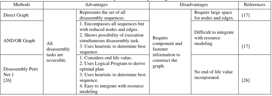
The research concept and objective is on the automation of the generation of the model from the CAD assembly from which the transition matrix showing the connection between components will be computed. The transition matrix is a guide to selection of disassembly sequencing methods. The case study pseudo-assembly used for the accomplishment of this research work is shown in Fig. 1. Disassembly sequencing involves the search for all possible disassembly sequences and the selection of the optimum solution out of these. In each application, a slightly different approach can be observed, including level of detail, degrees of freedom, and the role of uncertainty. Disassembly sequencing also plays a major role in the modern design process and is an invaluable tool in concurrent engineering. The sequencing methods all have their advantages but there is a need not just for any sequencing method but one that will have simplicity in sequencing, accuracy, flexibility and ease of translation to algorithm. Table 1 shows a comparison of different sequencing methods.
Fig 1: A Simple Mechanical Assembly
III. METHODOLOGY
The method to be employed in the disassembly sequencing is the AND/OR disassembly sequencing method. The choice of this sequencing is because of its ability to use heuristic methods in determining sequencing steps. This project aims to combine this selected sequencing method and MATLAB in automating the disassembly sequencing method. In general, the AND/OR graph can be defined as a directed graph in which each node represents the product or its possible subassemblies/components and each edge represents technically feasible disassembly operations. Here, the edges emanating from the same node are either in an AND relation or an OR relation with each other. That is, two edges are related by an AND relation if, and only if, an assembly can be disassembled by a single operation into two corresponding subassemblies, while a set of AND relation edges are related by an OR relation if, and only if, it is possible to disassemble an assembly into several other decompositions.
Unlike the direct diagram, the AND/OR graph [17], [22] – [23] introduces in the nodes the different subassemblies that have been produced in each step. The link between three nodes is called the hyper-arc, and it is a line that connects the ‘father’ and his two ‘sons’: it represents a feasible disassembly operation. In this graph, only the binary disassembly operations are taken into consideration. The division of (ABC) (Fig. 1) can be represented as the operation (A) AND (BC) OR (B) AND (AC) OR (C) AND (AB). The separation ends with the disassembly of all the initial assembly parts (A), (B) and (C). The search of the optimal disassembly sequence coincides with the study of the best method of crossing AND/OR graph. The set of the transactions and nodes, where all the alternatives coexist, defines the solution space of the disassembly problem. Assigning an appropriate weight to each hyper-arc and defining an objective function, it is possible to determine the best sequence. It is also possible to determine the amount of subassemblies in an assembly. The formula is given below; m is the number of parts in assembly. Also the number of operations that can be carried out can be computed from the formular below;
(1)
(2)
A. Software Used
B. Generating the CAD Model
Generating the model involves four phases; (i) Locating the single-part assembly Files (ii) viewing the CAD Assembly (iii) exporting the CAD Assembly In generating the SimMechanics Model, the first step was to locate the CAD file and then open it. The file was opened in the Solidworks environment. The file is then exported using the Simmechanics link, after which it is saved in the .xml format. It is in this format that the CAD assembly can be translated. It is called the Physical Modeling format (Physmod). The exported XML file is moved or copied into a MATLAB working directory to generate a SimMechanics model from the file. The model is then generated. The model displays the physical connection between parts of the assembly as well as their various properties such as; mass, principal moments of inertia, volume and surface area. The CAD assembly is displayed in Fig. 2 with its various properties.
The step-by-step process involved in determining the transition matrix from a CAD assembly can be tasking and time consuming, the generation of the model using Simmechanics greatly reduces the time spent on such endeavours, generating both the model and showing the connections between parts within seconds making it easier for the transition matrix to be computed from the connections in the model.
C. Simmechanics Model Generation
The Simmechanics model is generated automatically from the CAD assembly following the following procedures; (i) Moving or copying the exported XML file into a MATLAB working directory to generate a SimMechanics model from the file. (ii) Generating the model from cup_assembly.xml with the mech_import command. The SimMechanics model has blocks, a combination representing the entire assembly with the following properties. (i) The Ground origin is coincident with the World origin and maps the CAD assembly origin. (ii) The Root Part is a non dynamical zero-mass/zero-inertia body inserted between ground and the cup.
(iv) The second joint is a weld because the original CAD assembly has no degrees of freedom.
The model from the CAD assembly is shown in Fig. 3. From Fig. 3 the model has four parts; (i) Project 1 (ii) Project B (iii) Project C (iv) Project D. Based on the mates between the parts, corresponding joints are added to the models to link the mechanical parts together. Between Project1 and ProjectB, there is a coincident mate; the corresponding joint for a coincident mate is a planar joint, hence the coincident mate is translated as a planar joint. There are concentric mates between ProjectB and ProjectC and ProjectB and ProjectD; the corresponding joint is a cylindrical joint, hence both concentric mates are translated as cylindrical joints. The joints have varying degrees of freedom, for a planar, two cubes are constrained to allow two translational and one rotational degree of freedom between them, for the cylindrical Two cubes are constrained to allow one rotational and one translational degree of freedom between them.
D. Generation of Transition Matrix
[image:3.595.72.525.83.244.2]The joints between the simmechanics model parts are the parameters used in computing the transition matrix. The transition matrix is generated from the principle that; any connection or mate between two bodies is rendered as 1 whereas; if no connection exists it is rendered as a zero. The transition matrix consists of all the parts showing their connections to each other, from here the sequencing for disassembly can then be gotten. For example from Fig. 3 we can see that connections exists between A and B, B and C and B and D. Based on this sequencing procedures such as removing part A first then B, C and respectively can be developed. In fact various disassembly sequences can be generated from the transition matrix above. The time taken in the generation of the model and in the computation of the model compared to manual assessment of the assembly and then computation of the matrix is considerable, especially as the components of the assembly increase.
Table 1: Comparison of Sequencing Methods
Methods Advantages Disadvantages References Direct Graph
All disassembly tasks are reversible.
Represents the set of all disassembly sequences.
Require component and fastener information to construct the graph.
Require large space for nodes and edges. [17]
AND/OR Graph
1. Encompasses all sequences but with reduced nodes and edges. 2. Shows possibility of execution simultaneous disassembly task. 3. Uses heuristic to determine best sequence.
Difficult to integrate with resource modeling
[17]
Disassembly Petri Net 1
[26]
1. Considers end life value. 2. Uses Logical Program to derive optimal plan.
3. Uses heuristic to determine best sequence.
4. Easy to integrate with resource modeling
No end of life value incorporated.
Fig. 2: CAD Assembly Using Solidworks
Fig. 3: Simmechanics Model for CAD Assembly Using MATLAB
A B C D
A 0 1 0 0
B 1 0 1 1
C 0 1 0 0
[image:4.595.312.540.275.438.2]D 0 1 0 0
Fig. 4: Transition Matrix For CAD Assembly IV. APPLICATION OF DEVELOPED METHOD
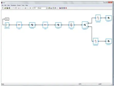
A second assembly involving twelve components was tested with the same procedure as that of the four part assembly. The CAD assembly diagram is shown in Fig. 5. From the connections between the components of the assembly in the generated model of Fig. 6, the transition matrix shown in Fig. 7 was generated. Despite the complexity of the model the connection between the parts of the transition matrix is generated easily just by considering the model showing the joints connecting various parts of the models.
[image:4.595.57.281.279.448.2]Fig. 5: Trial Assembly
[image:4.595.329.547.494.667.2]Fig. 6: Simmechanics Model Generated for Trial Assembly
Fig. 7: Transition Matrix for Trial Assembly
The joints also tell the degree of freedom for each component; hence the permitted motion of each part during disassembly process. These (transition matrix and relative motion of component parts) will help greatly in the choice of disassembly sequencing to use.
1 2 3 4 5 6 7 8 9 10 11 12
1 0 1 0 0 0 0 0 0 0 0 0 0
2 1 0 1 1 0 0 0 1 0 0 0 0
3 0 1 0 1 0 0 0 0 0 0 1 0
4 0 1 1 0 0 0 0 0 0 0 0 0
5 0 0 0 0 0 0 1 0 0 0 0 1
6 0 0 0 0 0 0 0 1 1 0 0 0
7 0 0 0 0 1 0 0 1 0 0 0 0
8 0 1 0 0 0 1 1 0 0 0 0 0
9 0 0 0 0 0 1 0 0 0 1 0 0
10 0 0 0 0 0 0 0 0 1 0 1 0
11 0 0 1 0 0 0 0 0 0 1 0 1
[image:4.595.117.220.509.604.2]V. CONCLUSION
1) The use of the simmechanics link in trying to compute the transition matrix and hence aiding the disassembly process, is time effective and with further research on the link, possibilities exist of finding better functions of the link than this developed in the course of this project. The possibilities also exist of determining the right amount of force to be applied to assemblies to destroy joints (in the case of destructive disassembly). The sequencing method can be developed from the various joints between component parts and the best option selected. The transition matrix developed through the course of this project serves as a basis for sequencing of disassembly.
REFERENCES
[1] K. Sebastian, S. Heyer , S. Chiotellis, G. Seliger, “Process planning for IT-equipment remanufacturing”. CIRP Journal of Manufacturing
Science and Technology, vol. 2, pp. 13-20, 2009.
[2] O.E. Simolowo, A. Mousavi, P.O. Adjapong, “A Computer-Based Product Classification and Component Detection for Demanufacturing Processes”. International Journal of Computer
Intergrated Manufacturing, vol. 24, no. 10, pp. 900 – 914, 2011.
[3] M. S. Abu Bakar, S. Rahimifard, Computer-aided recycling process planning for end-of-life electrical and electronic equipment, Proc.
IMechE. Part B: J. Engineering Manufacture vol. 221 2007.
[4] P. Ranky, S.C. Velumani, “A method, a tool (CORA) and application examples for analyzing disassembly user interface design criteria, International Journal of Computer Integrated Manufacturing” vol. 16, no. 4–5, pp. 317–325, 2003.
[5] D. F. Baldwin, T. E. Abell, M. M. Lui, T. L.De Fazio, and D. E. Whitney. “An integrated computer aid for generating and evaluating assembly sequences for mechanical Products”. IEEE Transactions
on Robotics and Automation, vol. 7, no. 78–94 1991.
[6] A. Bourjault, “Contribution a` une approche me´thodologique de l’assemblage automatise´: elaboration automatique des se´quences ope´ratoires (Besanc,on, France: Faculty of Science and
Technology, Universite´ de Franche-Comte´), Unpublished.
[7] A. Bourjault, D. Chappe,and J. M. Henrioud, “Elaboration automatique des gammes d’assemblage a` l’aide de re´saux de Petri”.
Rairo Apii, vol.21 pp. 323–342, 1984
[8] Capelli et al. “Design for disassembly: a methodology for identifying the optimal disassembly sequence” Journal of Engineering
Design vol.18, no. 6, 563–575, 2007.
[9] T. L. De Fazio, and D. E. Whitney, “Simplified generation of all mechanical assembly sequences”. IEEE Journal of Robotics and
Automation, vol. 3, no. 6, pp. 640–658, 1997
[10] R. B. Gottipolu, and K. Ghosh. “Representation and selection of assembly sequences in computer–aided assembly process planning”.
International Journal of Production. 1997
[11] A. Gungor, and S. M. Gupta. “Disassembly sequence planning for complete disassembly in product recovery.” Computers and Industrial
Engg, vol.35, pp.161-164, 1998
[12] A. Gungor, and S. M. Gupta, “Issues in environmentally conscious manufacturing and product recovery: a survey”. Comput. Ind. Engng, vol. 36, pp. 811–853, 1999.
[13] S. M. Gupta, and C. R. McLean, ”Disassembly of products”. Comput.
Ind. Engng, vol. 31, pp. 225–228, 1996.
[14] H. R. Holt, “Engineering Ecodesign,” in Proceedings of the North
Central Section Spring Conference ASEE, University of Toledo,
Ohio, pp. 321–328, 1992.
[15] H. R. Holt, A first step in electronic ecodesign, in Proceedings of the IEEE International Symposium on Electronics and the
Environment, San Fransisco, CA, 2–4 May 1994, pp. 191–195.
[16] S. A. Gerner, A. Kobeissi, B. David, Z. Binder, and B. Descotes-Genon, “Integrated approach for disassembly processes generation and recycling evaluation of an end-of-life product”. Int. J. Prod. Res., vol. 43 no.1 pp.195–222, 2005.
[17] L. S. Homem de Mello and A. C. Sanderson, “AND/OR graph representation of assembly plans.” IEEE Trans on Robotics and automation vol. 6, no. 2, pp.188-199, 1990.
[18] ISO 10303-21, Industrial automation systems and integration: product data representation and exchange – part 21. Implementation methods:
clear text encoding of the exchange structure, ISO, Geneva, Switzerland, 1994
[19] A. J. D. Lambert, “Optimal disassembly of complex products.” Int’l
Journal of ProductionResearch vol. 35, no.9, pp. 2509-2523, 1999.
[20] A. J. D. Lambert. “Disassembly sequencing”: A survey, Int. J. Prod. Res., vol. 41, no. 16, pp. 3721–3759, 2003
[21] A. J. D. Lambert. and S. M. Gupta, “Demand-driven disassembly optimization for electronic products”. J. Electron vol. 11, pp. 121–
Askiner, G. and Gupta, S, M., Disassembly sequence planning for products with defective parts in product recovery. Comput Ind Eng 1998, 35, 161–164
[22] A. J. D. Lambert Research. “Disassembly sequencing: a survey” Int.
J. Prod. Res., vol. 41, no. 16, pp. 3721–3759,2001.
[23] A. J. D. Lambert. ”Optimal disassembly sequence generation for combined material recycling and part reuse”. Proceedings of the IEEE International Symposium on Assembly and Task Planning, Porto,
Portugal, pp. 146–151, 1997.
[24] Mathworks Inc R2009A. Help
[25] M. G. Santochi, F. Dini,, “Computer Aided Disassembly Planning: State of the Art and Perspectives; Dept of Mechanical, Nuclear and Production Engineering, University of Pisa.
[26] T. Suzuki, “On algebraic and graph structural properties of assembly of Petri net.” Proc of IEEE Int’l Conf on Robotics and Automation
San Francisco, CA 2000 pp. 2197-2202.
[27] J. Chung, Y. Koh, H. Lee, and T. Hur, “Web based ecodesign supporting system for electronic products”. Proceedings of IEEE International Symposium on Electronics and the Environment,
Boston, MA, 12–14 May 2003, pp. 246–250.
[28] Das, S., Yedlarajiah, D. and Gurram, S., DISX: “A procedure for the automated generation of disassembly process plans”. Proceedings of the IEEE International Symposium on Electronics and the
Environment, Boston, MA, 12–14 May 2003, pp. 60–65.
[29] M. Klausner, W. Grimm, and C. Hendrickson, “Reuse of electric motors in consumer products”. J. Ind. Ecol., vol. 2, pp. 89–102, 1998.
[30] Kuo and C. Tsai, “Disassembly sequence and cost analysis for electromechanical products”. Robot Com-Int. Manuf., vol. 16, pp. 43–54, 2000.
[31] S. Gupta, “Demand-driven disassembly optimization for electronic products”. J. Electron. Mfg, vol. 11, pp. 121–135, 2002.
[32] M. Peng, D. Guanghong, X. Dong, L. Xeuping, W. Ying, L, Fangyi, and L. Yi, “An information system management of assessment of disassembly and recycle”. Proceedings of the IEEE International
Symposium on Electronics and the Environment, Boston, MA, 12–14
May 2003, pp. 286–290.
[33[ G. Seliger, B. Basdere, T. Keil, “E-cycling platform for profitable reuse”. Proceedings of the IEEE International Symposium on
assembly and Task Planning, Fukuoka, Japan, 2001, pp. 453–457.