Abstract— This paper proposes a maximum power point tracking using fuzzy based perturb and observe (P&O) algorithm for a photovoltaic (PV) system (an AC module). In AC module flyback inverter, modulation index (∆ma) are adopted as a control variable to track the maximum power point (MPP) of PV array. In the conventional technique, step size of modulation index (∆ma) is adopted in the simple P&O technique; Although this technique is easy to be implemented but there is some problems regarding large oscillation around the MPP and slow tracking when improper step size is selected. The proposed technique, fuzzy based P&O technique, is adopted to provide non-equal step
size of ∆ma. The proposed fuzzy system was
programmed on microcontroller which is a low cost processing device. Experimental result confirms that the proposed system can effectively track the power from PV system, and is better than the conventional technique.
Index Terms—AC-module, fuzzy MPPT, flyback inverter,
discontinuous mode.
I. INTRODUCTION
OWADAYS, interest in an AC module in photovoltaic energy has grown to solve the problem of environment crisis. Photovoltaic (PV) systems have been developed to overcome the problem of energy crisis. Solar energy generators are extensively adopted to generate the electrical power from solar irradiation. In this approach, solar power is converted into electric power by photovoltaic (PV) array. The output of the PV panels depends on surrounding weather conditions those are sun irradiance level and temperature [1-3]. Several circuits and control schemes for photovoltaic power generation systems were applied and studied. Generally, a PV system consists of PV array and PV power conditioner that can be divided into two categories, first is dc–dc converter to control the dc voltage and second is inverter to generate ac power [4].
In this paper, a flyback inverter with center-tapped secondary winding is adopted for implementing the
Manuscript received Febuary, 2013; This work was supported in part by the King Mongkut’s Institute of Technology Ladkrabang Research Fund.
Somyot Kaitwanidvilai is with the Faculty of Engineering, King Mongkut’s Institute of Technology Ladkrabang, Thailand. (corresponding author to provide phone: 883-906-6567; e-mail: drsomyotk@ gmail.com).
Poom Konghuayrob is with the Faculty of Engineering, King Mongkut’s Institute of Technology Ladkrabang, Thailand. (e-mail: [email protected]).
proposed technique, fuzzy based P&O algorithm. The design of this circuit was presented in the references [5]– [7]; the features of flyback inverter are summarized here as follows. No dc–dc converter is required and the flyback inverter can directly convert the specified dc power to ac power. The main circuit configuration is simple and the number of power semiconductor switches used is less than that of the other circuits. This research work adopts the fuzzy maximum power point tracking (MPPT) technique to utilize the power from PV array.
Modulation index (flyback inverter) and duty-cycle (DC-DC converter) are key parameters for tracking MPP of solar array [8]. Although general P&O technique can be simply adopted for the tracking purpose, the selection of appropriate step size of modulation index (Δma) or duty cycle is not easy. If the step size is too high, the oscillation around the maximum power point (MPP) will be large. On the contrary, results of tracking will be slow if the step size is low. To overcome this problem, this paper proposes the fuzzy based P&O algorithm to adjust the appropriate Δma to achieve both fast tracking and low MPP power oscillation. The inputs of the proposed fuzzy logic are the magnitudes of the change of power (ΔP) and the change of PV voltage (ΔV) which are used to estimate the appropriate Δma. The system was programmed on microcontroller; thus, the cost of controller are reduced when compared to DSP or personal computer. The experimental results show that the proposed technique can perform efficient power tracking in various irradiance conditions.
II. FLYBACK INVERTER WITH CENTER-TAPPED SECONDARY WINDING
A. Operation of DCM-flyback inverter with
center-tapped secondary winding
[image:1.612.315.541.582.668.2]Load
Fig. 1. Circuit configuration of grid connected flyback inverter with center-tapped secondary winding.
The main circuit of DCM-flyback inverter for a prototyped PV power conditioner is shown in Fig. 1. PV module is utilized as the input source of this inverter. A
Microprocessor based Fuzzy MPPT for PV-AC
Module DCM-flyback Inverter
Poom Konghuayrob and Somyot Kaitwanidvilai
flyback inverter consists of one decoupling capacitor, one center-tapped secondary winding transformer, three semiconductor switches, two power diodes and LC output filter. The primary switch Sprioperates with high switching
frequency, secondary switches Ssec1and Ssec2 operate with 50
Hz like as line frequency. The capacitor (C1) is used to reduce ripple component of input power because nearly constant input voltage and current is needed for MPPT algorithm. The flyback transformer performs energy flow from dc to ac side and provides isolation between the PV array and ac line for protection. The primary winding is connected to the PV array and the MOSFET Sp, where the switch Spri is driven by pulse-width modulated gate pulses
[image:2.612.316.542.254.594.2]generated by triangle compared with absolute sine. Both of AC semiconductor switches composed of the IGBTs Ssec1, Ssec2 and the diodes D1,D2 in series connection as shown in
Fig. 3, connected to each terminal of the secondary winding of the flyback transformer. The active switches Ssec1 and Ssec2 are turned on or off on each of half line cycle to
generate positive or negative output current according to the polarity of the sinusoidal waveform.
sec1
S
f
L
Load
Mode I
D1
D2
Cf
Load
Ssec2
PV Module
Lm Cin
Spri
Vin
f
L sec1
S
Mode II
sec1
S
f
L
Load
Mode III
Load
Mode IV
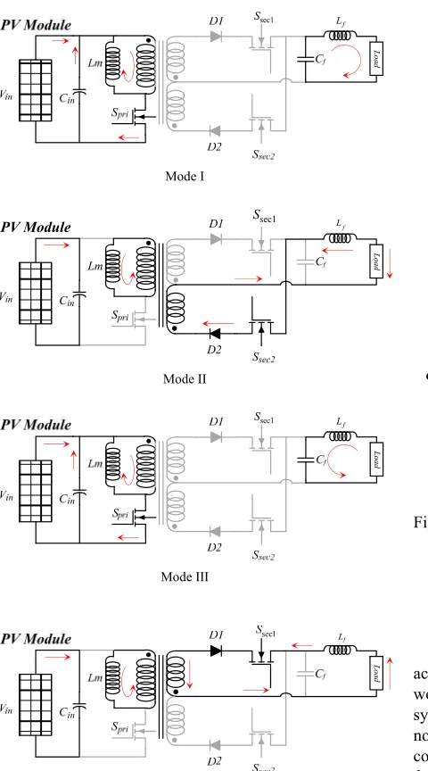
Fig. 2. Circuit configuration and operation modes of flyback inverter.
The circuit of flyback inverter and the switching sequences (mode) are shown in Fig. 2. Mode I is defined for the situation where switch Spri is conducted and all other
switches are off, and the stored energy in Cf is discharged to
the AC load or grid with the synchronized polarity and phase. Mode II is defined for the duration where IGBT Ssec1
is conducted with all the rest in off, implying the stored energy in Lm releases to the AC utility grid and giving the
positive polarity. Mode III and IV, the primary switch Spri
alternately operates at high switching frequency during the negative half cycle. The thorough analysis of the DCM flyback inverter is described in [9]. The transferred power is expressed by the following equation [9]:
2 2
1 4
PV dc L p
P V g d (1)
where
1
1
L s g
L f
(2)
Ts ton toff
PWM Generator
Spri Ssec-1 Ssec-2
Secondary Current Primary Current
Ipri , Isec
[image:2.612.81.321.299.731.2]20 ms
Fig. 3. Current waveform and switching sequence diagram
III. PROPOSED FUZZY BASED P&O ALGORITHM
The operation of the proposed fuzzy logic control is shown in the flow chart in Fig. 4. Solar PV system consists of a PV panel, a flyback inverter, fuzzy based P&O MPPT control unit and load which are shown in Fig.1. The power from PV panel is delivered to the load through the flyback inverter. The change of output voltage (∆Vpri) and the change of
power (∆Ppri) from the PV panel are adopted as the inputs of
[image:3.612.320.534.47.337.2]the fuzzy based MPPT control unit for MPP tracking. Fuzzy logic is used to determine the step size of perturbed modulation index. In the other words, the proposed fuzzy logic P&O MPPT will decide the new operating voltage for PV panel by adjusting the step size of modulation index (∆ma) on the flyback inverter.
Fig. 4. Operation of fuzzy logic based P&O MPPT control
In this paper, fuzzification is the process of converting (∆Vpri) and (∆Ppri) from PV array, which are the inputs of
fuzzy system, into linguistic fuzzy sets using fuzzy member-ship function with six fuzzy sets: NB (negative big), NM (negative medium), NS (negative small), PS (positive small), PM (positive medium), and PB (positive big). Fig. 6 shows the input membership functions of this proposed technique. 5 fuzzy sets of output membership are VB (Very Big), B (Big), M (Medium), S (small), VS (very small).
TABLEI
RULES OF FUZZY BASED P&O SYSTEM
Change of
voltage Change of power(∆Ppri)
(∆Vpri) NB NM NS PS PM PB
NB VS S M M S VS
NM B VS S S VS B
NS VB B VS VS B VB
PS VB B VS VS B VB
PM B VS S S VS B
PB VS S M M S VS
TABLEII
DESCRIPTION OF WEIGHT VALUES
Rule No
Value of membership
function
∆ma weight (Wk)
1 VB 6×10⁻²
2 B 4×10⁻²
3 M 3×10⁻²
4 S 2×10⁻²
5 VS 1×10⁻²
∆ma
Start
Initialize Pold = 0 ma = 0.1 Increment (a) = 1
Pm-Pm-1= 0
Pm-Pm-1> 0
a = -a
ma < mamin
ma = mamin
ma > mamax
Keep ma
ma = mamax
ma = ma+a*∆ma
Yes
Yes No
No
No
No
Yes Yes
Measure Vpri, Ipri
Fuzzy based P&O algorithm
Find ∆Ppri , ∆Vpri
Fig. 5. Flow chart of the proposed fuzzy based perturb and observe (P&O) for MPPT of flyback inverter
0.5 1
NB NM NS PS PM PB
5 4 3 2 1 0 -1 -2 -3 -4 -5 0
Membership function sets
[image:3.612.75.290.210.257.2]Input variable “ V”
Fig. 6. Membership functions of the input variables (∆Vpri and ∆Ppri)
[image:3.612.319.534.378.582.2] [image:3.612.74.295.410.662.2]1
1
m k
k k
m
k k
u w ma
w
(3)where ∆ma is the step size of modulation index. ukis the product of all membership values of rule no. k, and wk is
[image:4.612.312.541.44.248.2]the weight of rule no. k; m is the number of rules. As seen in Fig. 5, ∆ma is used as the magnitude of change but the direction of change is specified by the concept of simple P&O. AC-module flyback inverter adopts the output of fuzzy system (the step size) to the P&O method to generate pulse width modulation (PWM) signal for controlling primary switch Spri.
[image:4.612.130.228.48.110.2]
Fig. 7. Sugeno output surface (Δma)
IV. EXPERIMENTAL RESULTS
[image:4.612.81.283.255.379.2]The effectiveness of flyback inverter and the proposed fuzzy system are verfied by simultaion with Matlab/Simulink and real experiment. Flyback inverter model in MATLAB is shown in Fig 8. The PV system adopted in this study is composed of 100W. PV panel and Fly back inverter with 30 kHz switching frequency.
Fig. 8. Simulink model of fly back inverter
In order to show the effectiveness of the proposed fuzzy based P&O, both the proposed and the conventional P&O techniques were implemented on the MPPT. The results of
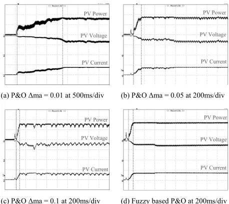
(a) P&O Δma = 0.01 at 500ms/div (b) P&O Δma = 0.05 at 200ms/div
[image:4.612.314.539.302.432.2]
(c) P&O Δma = 0.1 at 200ms/div (d) Fuzzy based P&O at 200ms/div
Fig. 9. Real power, voltage and current of flyback inverter (a),(b) and (c) are experimental results of the conventional P&O (d) is the experimental result of the proposed fuzzy base P&O MPPT algorithm. (at irradiance level 450 W/m2)
0 0.1 0.2 0.3 0.4 0.5 0.6 0.7 0.8 0.9 1
∆ma =
0.01 P&O
∆ma =
0.025 P&O
∆ma =
0.05 P&O
∆ma =
0.1 P&O
Fuzzy based P&O
0 2 4 6 8 10 12 14 16
∆ma = 0.01 P&O
∆ma = 0.025 P&O
∆ma = 0.05 P&O
∆ma = 0.1 P&O
Fuzzy based P&O
Fig. 10. The comparison results of the proposed and the conventional techniques
Figs. 9 (a), (b) and (c) show the results of power, voltage and current from the conventional MPPT algorithm when operted at irradiance level = 450 W/m2. Fig. 9(d) shows the
experimental results of the proposed fuzzy logic control based P&O algorithm. As seen in Fig. 9(c), high value of step size Δma results in fast tracking and high oscillation of power at MPP. In contrary, as shown in Fig. 9(a), low value of step size results in slow tracking and low oscillation of power at MPP. In Fig. 9(d), the results of tracking time and power oscillation concern that the proposed technique is better than the conventional technique in terms of lower power oscillation and faster tracking. Fig. 10 shows the bar graph of the results from Fig. 9.
V. CONCLUSION
In this paper, flyback inverter with center taped secondary winding using fuzzy based P&O algorithm for AC module system has been proposed. The proposed MPPT technique is adopted to approximate the appropriate Δma for achieving good power oscillation and fast tracking. The
PV Power
PV Voltage
PV Current
PV Power
PV Voltage
PV Current
PV Voltage
PV Current PV Power
PV Voltage
PV Current PV Power
[image:4.612.72.297.510.636.2]ACKNOWLEDGMENT
This work was supported by King Mongkut’s Institute of Technology Ladkrabang Research Fund.
REFERENCES
[1] Y-C. Kuo, T-J. Liang and J-F. Chen. Novel Maximum-Power-Point-Tracking Controller for Photovoltaic Energy Conversion System, IEEE Transactions On Industrial Electronics, Vol. 48, No. 3, June 2001, pp.594-601.
[2] M. A. S. Masoum, H. Dehbonei, and E. F. Fuchs. Theoretical and Experimental Analyses of Photovoltaic Systems with Voltage- and Current-Based Maximum Power-Point Tracking, IEEE Transactions On Energy Conversion, Vol. 17, No. 4, December 2002, pp.514-522. [3] L. Fangrui, Y. Kang, Y. Zhang, and S. Duan. Comparison of P&O
and Hill Climbing MPPT Methods for Grid-Connected PV Converter,"Industrial Electronics and Applications, 2008, ICIEA 2008. 3rd IEEE Conference on. pp. 804-7. 2008.
[4] N. Kasa, T. Iida, L. Chen, “Flyback inverter controlled by sensorless current MPPT for photovoltaic power system,” IEEE Trans. Ind. Elec., vol. 52, no. 4, pp. 1145-1152, 2005.
[5] N. Kasa and T. Iida, “A flyback type inverter for small scale wind power generation system,” (in Japanese), Dept. Electron. Eng., Okayama Univ. Science, Okayama, Japan, Tech. Rep. SPC-02-16, Feb. 2nd, 2002.
[6] “Photovoltaic systems with flyback type inverter” (in Japanese),J. Jpn. Soc. Power Electron., vol. 27, pp. 187–192, Mar. 2002. [7] T. Shimizu, K. Wada, and N. Nakamura, “A flyback-type single phase
utility interactive inverter with low-frequency ripple current regulation on the DC input for an AC photovoltaic module system, IEEE 33rd Annual on power electronics.,Vol. 3,pp. 1483-1488,2002. [8] Nicola Femia, Giovanni Petrone, Giovanni Spagnuolo, etc.
“Optimization of Perturb and Observe Maximum PowerPoint Tracking Method,” IEEE Trans. on Power Electronics., Vol. 20, No. 4, pp. 963-973, 2005.
[9] Kyritsis, A.Ch.; Tatakis, E.C.; Papanikolaou and N.P, “Optimum Design of the Current-Source Flyback Inverter for Decentralized Grid-Connected Photovoltaic Systems,” Energy Conversion, IEEE Transactions on ., Vol. 23, No. 1, pp. 281–293, 2008.