A Tick Based Fixed Priority Scheduler Suitable
for Dataflow Analysis of Task Graphs
A master’s thesis
Written by:
Jorik de Vries
University of Twente
Committee:
M.J.G. Bekooij
J.F. Broenink
G. Kuiper
A Tick Based Fixed Priority Scheduler Suitable for
Dataflow Analysis of Task Graphs
Jorik J. de Vries
University of Twente
[email protected]
ABSTRACT
Task graphs of real-time stream processing applications can be modeled using dataflow graphs. Dataflow analysis can then be used to determine maximum finish times of the tasks, including delays due to Fixed Priority Preemptive (FPP) scheduling. However, acquires and releases of con-tainers happen atomically in the dataflow model, which can-not be guaranteed by existing Real-Time Operating Sys-tems (RTOSes).
In this paper we propose a tick-based FPP scheduler for which maximum finish times can be derived using an ex-tended dataflow model. For this specific scheduler, it can be shown that the finish times are pessimistic, even if tasks acquire and release non-atomically.
Results obtained using an event-driven simulator confirm that the finish times derived for a non-tick based FPP sched-uler are optimistic, whereas the finish times derived for the proposed scheduler are pessimistic.
1.
INTRODUCTION
Real-time stream processing applications, such as software defined radios, are often implemented as a set of event-driven tasks on a multiprocessor system. Most real-time applica-tions require that minimum throughput constraints are sat-isfied, and from the worst-case finish times of the tasks the guaranteed throughput of the application can be obtained.
Usually, it cannot be assured that the finish times ob-tained from simulations or measurements are the worst-case finish times. A way to analytically determine the maxi-mum finish times is by using dataflow models and analy-sis. Dataflow models support the modeling of the cyclic de-pendencies in an application, as well as tasks with multiple inputs and outputs. Recently, dataflow analysis has been extended to be able to calculate the maximum throughput and maximum latency of systems in which FPP scheduling is applied [10, 14, 17, 24].
In FPP scheduled, event-triggered systems, the execution of a task is started by the arrival of data, instead of by a timer. The start of a task is triggered by accompanying data transfers with for example an interrupt [16, 22]. How-ever, the interference caused by servicing interrupts can in-crease maximum finish times of tasks severely in case data arrives in bursts. Furthermore, the design of the multi-core architecture determines whether interrupts can be sent be-tween processors, and what happens if a processor cannot respond quickly enough to an interrupt. The behaviour of interrupt-based schedulers can thus be different depending on the architecture.
Another problem with determining maximum finish times of event-driven, FPP scheduled tasks is that the dataflow
T1 T2 A1 A2
Figure 1: A task graph and corresponding dataflow graph, where non-atomic releases of T2 result in
op-timistic bounds.
analysis techniques are only applicable if the dataflow model or the RTOS satisfies certain requirements. The worst-case finish times determined by dataflow analysis are only pes-simistic if the model does not have cyclic dependencies, or if the RTOS guarantees that acquiring and releasing con-tainers happens atomically. However, nearly all non-trivial applications contain cyclic data or resource dependencies, and no RTOS was found that guarantees that multiple se-quential acquires or releases happen atomically.
Figure 1 shows a task graph and corresponding dataflow
model, where A1 models T1, and A2 models T2. Due to
non-atomic releases in the task model the maximum fin-ish times of the tasks can be later than derived from the dataflow graph. The two actors in the dataflow model are mutually exclusive due to the cyclic dependencies with one token, this is used by [13] to tighten the maximum finish
times of the actors. However, if task T2 releases the
con-tainer non-atomically, the two tasks cannot be guaranteed to be mutually exclusive. This is because with non-atomic releases the scheduler can issue a context switch between
the two releases done by T2. With this context switch T1
can start before taskT2 is finished, and the maximum finish
times derived from the dataflow model will thus be
opti-mistic forT2.
P1 IC IC P2 I12
I21
system bus
M (a) With IC.
P1 P2
I12 I21
system bus
M (b) Without IC.
P1 P2
system bus
M
(c) No interrupts.
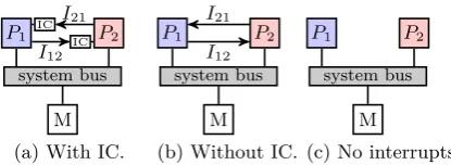
Figure 2: Different multi-core architectures.
2.
RELATED WORK
In this section, we discuss related work. First different FPP schedulers will be discussed, and how the tick-based scheduler differs from these. It will then be explained how a task set can be analysed to determine the maximum finish times needed for throughput and latency guarantees.
An overview of different classes of FPP schedulers has been given in [7, 25]. The focus of these schedulers is to limit the number of preemptions in order to decrease the maximum finish times of tasks. An example of such an FPP scheduler is the Deferred Preemptive Scheduler [3]. In this scheduler, a preemption is delayed for a certain time to al-low the al-lower priority task to finish before the preemption. In the tick-based scheduler, tasks are also guaranteed a cer-tain execution time, but this is a result of the periodic check used to remove the need for interrupts. A scheduler with-out interrupts was also proposed in [6], but this scheduler fails to address problems surrounding non-atomic acquires and releases of tasks. Furthermore, a tick or periodic FPP scheduler was proposed in [11, 21] but these schedulers only supported time-driven, and not event-driven applications.
The problems with non-atomic acquires and releases in event-driven systems have been addressed in [12, 19]. Non-atomic releases have also been addressed specifically for FPP scheduling in [9, 11], but none of these papers suggest a definitive answer. The proposed scheduler is able to solve the interferences and problems from non-atomic releases.
Response time analysis for real-time FPP scheduled ap-plications was introduced by Liu [18]. Research has since focused on broadening the scope of the analysis techniques, for example by allowing blocking time [1, 5], and precedence relations between tasks [20]. Furthermore, dataflow models were introduced to handle arbitrary cyclic dependencies be-tween tasks. Dataflow analysis has been able to include scheduling delays and interferences in the dataflow model for starvation free schedulers [23], and for non-starvation free schedulers [10]. Dataflow analysis techniques for non-starvation free schedulers has been introduced in [13, 24]. These dataflow analysis techniques assume that acquires and releases of tasks are atomic. For existing RTOSes this as-sumption does not hold.. It will be shown that the con-clusions of the techniques can be false if this assumption is violated.
3.
BASIC IDEA
In this section the basic idea of the tick-based FPP sched-uler will be described. First, the different architectures on which the scheduler can be applied will be explained, after which the basic operations of the scheduler will be explained. Event-driven schedulers are often dependent on interrupts accompanying events. This ensures that a scheduler is able
T1 T2 A1 A2
2
Figure 3: The one-to-one relation between task graph and dataflow model.
to respond as soon as possible to an incoming event. How events are sent and received differs per architecture. As it depends on the available hardware of the system, the same scheduler will thus behave different depending on the archi-tecture. Three different multi-core architectures are shown in Figure 2.
In the architecture shown in Figure 2a the processors have an Interrupt Controller (IC). An IC receives all interrupts, sets an appropriate flag, and raises the interrupt pin of the processor. This allows the processor to temporarily delay servicing an interrupti, as the flag in the IC remains set until the processor explicitly clears it.
The architecture in Figure 2b shows a system without an IC. Interrupts in this system have to be serviced immedi-ately or they are lost. Bounding the arrival rate of interrupts becomes important, because interrupts have to be serviced before the next interrupt arrives.
The third architecture depicted in Figure 2c shows a sys-tem where processors cannot communicate with each other using interrupts. An example of such a system is the Star-burst [8]. Communication between processors goes via shared memory, instead of sending interrupts. The architecture needs less pins in hardware because no dedicated interrupt lines are present.
In order to increase the applicability of the tick-based FPP scheduler, it will be focussed on the architecture shown in Figure 2c. All the hardware present in this architecture is also present in the other architectures, therefore the sched-uler will be able to run on all systems. Furthermore, the lack of interrupts will ease the analysis, as the arrival rate and interference of interrupts will not have to be bounded.
A task graph is a set of tasks and with dependencies be-tween the tasks. It will be assumed that all task dependen-cies represent communications through FIFO buffers, these are shown in Figure 3 as red (full) or green (empty) blocks on the dependencies. In this paper, it will furthermore be assumed that task priorities are inversely proportional to the task number, and a task is bound to the processor with the same color. The tasks in the task graph shown in Fig-ure 3 are thus all bound to one processor. The dependency between tasks can with these assumptions be modeled as two edges with tokens towards the actor modeling the con-suming tasks modeling full containers and tokens on the backwards edge modeling empty container. As tasks cannot execute auto-concurrently, the actors modeling a task will have a self-loop with one token, resulting in the equivalent models shown in Figure 3.
[image:3.595.71.279.64.140.2]0 2 4 6 8
[image:4.595.54.293.50.98.2]P1 S T1 S T2 S T2
Figure 4: Example trace of a task graph scheduled by the tick-based scheduler.
with multiple acquires and releases, tasks are unable to in-terfere, thereby removing the sources of interference due to the non-atomic acquires and releases. This is done by trans-fering the action of releasing containers from the tasks to the scheduler.
Furthermore, the proposed scheduler is triggered not by the arrival of interrupts, but by a timer or a finishing task. At these intervals, the scheduler will check the buffers whether a new task is enabled, and release containers produced by the previous task. An example execution trace of the tick scheduler using the task graph of Figure 3 is shown in Fig-ure 4. The grey blocks are the scheduler executing, a down arrow means an container is acquired, whereas an up arrow means a container is released. A straight bar signals a trig-ger of the scheduler. Which can for example be the finish of a task shown at time-unit 2, or the passing of the tick-period shown at time-unit 7.
The interferences due to this scheduler are easier to in-corporate in dataflow models than the interferences due to non-atomic acquires and releases. Interferences are now experienced only if the scheduler is triggered, which hap-pens at a known constant interval, whereas in other FPP schedulers all incoming data triggers interrupts which acti-vate the scheduler. Furthermore, the interferences due to non-atomic acquires and releases are hard to capture in the dataflow model, thereby potentially making the results of dataflow analysis incorrect. These interferences and their consequences will be shown in the next section.
4.
COMMUNICATION PROBLEMS
In this section, the problems surrounding communicating tasks will be discussed. The non-atomic implementation of multiple consumptions and productions will introduce de-lays not accounted for by dataflow analysis techniques. This will result in optimistic maximum finish times. Further-more, it will be shown that interrupts accompanying data might introduce significant interference, and finding bounds on this interference is hard.
4.1
Consumptions
In this section, the consequences of non-atomic acquires at the start of an execution of a task will be discussed. It will be shown that due to non-atomic acquires, the max-imum finish times derived using dataflow analysis can be optimistic. Furthermore, it will be shown that tighter finish time bounds derivation using mutual-exclusivity of actors [13] depend on the assumption of atomic acquires at the start.
Preempting the execution of a task costs processing time. This switching overhead can be accounted for by extending the Worst-Case Execution Time (WCET) of a task in the task graph with the maximum time it costs to initiate a context switch [2, 4]. Due to non-atomic acquires, a task is able to initiate more than one preemption during one ex-ecution. As a result, appending the WCET with a single
A1 A2
e4 e2
e3
e1
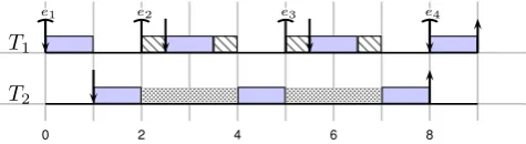
Figure 5: Dataflow model where non-atomic ac-quires can result in optimistic bounds.
0 2 4 6 8
T1
T2
e2 e3 e4
e1
Figure 6: A possible trace if the tasks have non-atomic releases.
context switch will result in optimistic finish times. To implement a data transfer between tasks, an RTOS
has calls available such as acquire(ex). These calls
sus-pend a task until the variable is written in the buffer and the task can consume the value from the buffer. Acquir-ing multiple variables can be done by callAcquir-ing a number of acquire calls sequentially. With the current RTOS designs, problems will arise because calling multiple acquires is not an atomic action.
The dataflow model shown in Figure 5 will be used to demonstrate the consequences of non-atomic acquires. The tasks corresponding to the actors have the same number,
and it will be assumed that taskT1 does the acquires in the
order of the suffix of the edges. The data of the edgese2and
e3 will arrive in this example respectively at times two and
five, resulting in the trace shown in Figure 6. Because T1
has the highest priority, the scheduler immediately issues a
context switch once the data one2arrives, during this switch
T1 will execute a single acquire and suspend as the variable
one3 is not yet available. This sequence is repeated when
the container of edgee3 is released. From Figure 6 it can
be concluded that taskT1 is able to issue multiple context
switches during one enabling. Extending the WCET of a task by accounting for a single context switch will thus result in optimistic maximum finish times.
The two actors in Figure 5 execute mutually-exclusive due to the cyclic dependency with one token. This info can be used to derive a tighter bound on the maximum finish times, because it should imply that the interference between tasks is limited by this cyclic dependency. However, from Fig-ure 6 it can be concluded that the execution of tasks is not guaranteed to be mutual-exclusive if acquires can
hap-pen non-atomically. Task T1 is able to preempt task T2,
which cannot happen for mutually-exclusive tasks. Sequen-tially calling the acquires mean that part of the execution of a task is not guaranteed to be mutually-exclusive. The tighter finish times derived by [13] are thus only pessimistic if acquires happen atomically at the start of an execution.
4.2
Productions
[image:4.595.318.556.150.215.2]A2 A3
A1
e2 e3
e1
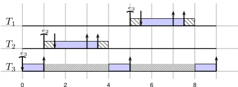
Figure 7: Dataflow model where non-atomic releases can result in optimistic bounds.
0 2 4 6 8
T1
T2
T3 e2
e3
e3
Figure 8: Possible trace if the tasks have non-atomic releases.
the finish times derived using mutual-exclusivity of actors [13] are optimistic if releases can happen non-atomically.
To implement data transfer between tasks, an RTOS has
calls available such as release(ex). These calls release a
value written in the buffer such that consuming tasks can acquire the variable. If a task has to release multiple vari-ables, it can call multiple release statements sequentially. Problems arise because calling multiple release statements is not an atomic action.
The dataflow model shown in Figure 7 will be used to demonstrate the problems resulting from non-atomic releases.
The task corresponding toA3 will release containers in the
order of the subscript of the edges. With this order, the execution trace shown in Figure 8 can be obtained. The
momentT3 releases the variable forT2, the scheduler issues
a context switch due to the higher priority ofT2. As a
re-sult, the release of the container forT1is delayed. The start
time, and thereby the finish time, ofT1 is thus delayed by
the execution of the lower priority taskT2.
This delayed start of tasks is hard to include in the analy-sis, and will result in very pessimistic maximum finish times. It is hard to include in the analysis because the worst-case order of releases is different for every task. Therefore, the analysis will, for every task, have to determine the worst-case order of releases of all tasks in the graph, and calculate how it influences the start time of a task. The different scenarios for each task also cause the determined maximum finish times to be very pessimistic, for example in Figure 8.
The tasks corresponding to actorsA1andA2will determine
a different order of releases for the task corresponding to A3. The analysis must thus calculate the bounds with two different orders of releases for a single task, but in the im-plementation only one of the possible orders will occur. As a result, one of the bounds will indicate finish times that are later then possible in reality.
The described problem is only present if a task enables a higher priority task on the same processor. An appar-ent solution could thus be to reorder priorities of tasks such that tasks only release containers for lower priority tasks. This solution is infeasible with cyclic dataflow graphs, such
as Figure 7, because the task corresponding to actorA1
re-leases a container for the task corresponding toA3, therefore
its priority should be higher. On the other hand the task
A1 A2 A3
2 2
2
2
2
[image:5.595.53.293.137.225.2]2
Figure 9: Dataflow model used to show that non-atomic releases result in more interference due to interrupts.
corresponding toA3 releases a container for the task
corre-sponding toA1, therefore its priority should be higher. With
fixed priorities it is impossible to satisfy both constraints at the same time.
The execution of actorA2in Figure 7 is mutually exclusive
from the execution of the other two actors, because of the cyclic dependencies with a single token on them. This is used by [13] to limit the interference of actors and thus derive tighter maximum finish times. However, from Figure 8 it can be concluded that if releases happen non-atomically at the end of the execution of a task, a part of the execution is not guaranteed to be mutually exclusive. As a result, more interference is possible than expected from the analysis and finish times will be later then determined using dataflow analysis.
4.3
Interference from interrupts
In this section, the interference due to communication be-tween tasks will be discussed. Communication causes inter-ference, as sending data or an event is often accompanied with an interrupt to ensure quick responses. Problems arise because it is hard to limit the arrival rate of interrupts for an RTOS.
The scheduler is implemented using two queues. The ready queue holds tasks ready for execution, and the sus-pended queue holds tasks waiting for a specific event. A task is moved from the ready to the suspended queue if the task executes an acquire call for a not yet released container. The task is moved back to the ready queue if the interrupt signalling that the required container has been released is re-ceived. This design results in a minimalistic scheduler, the scheduler does not need to cope with the case that a task needs events from multiple inputs before it can start its ex-ecution. It only needs to check whether a received interrupt enables a task, and if so, move this task to the ready queue. If a task is moved from or to the ready queue, the scheduler furthermore needs to ensure that the highest priority task is processed.
The downside of this approach is that all interrupts have to be serviced to avoid deadlocks. Assume for example that in Figure 9 the event accompanying the release of the
con-tainer between the tasks modeled by A2 and A3 is missed.
As a result, the task will not move from the suspended queue towards the ready queue, although the container is available. Unfortunately, the dataflow model shows there is only one token available between the actors, thus the interrupt will not be sent again. This system will thus immediately dead-lock after an event is missed.
of the tasks on the receiving processor might thus not be pushed onto the ready queue. On this architecture, non-atomic releases are thus not only a result of the RTOS, but non-atomic releases are a constraint to ensure all interrupts can be serviced.
All interrupts received should be serviced by the proces-sor. A consequence of this is that not only the arrival rate of interrupts due to the releases of a single task needs to be bounded, but also the arrival rate of all received interrupts. Take for example the dataflow graph of Figure 9. The blue processor will receive four interrupts if the tasks
correspond-ing to A1 and A3 start releasing at the same time. If the
tasks release the two containers satisfying the arrival rate constraint, the blue processor will still receive four inter-rupts in the time it can service two. Therefore, it has to be guaranteed that all received interrupts satisfy the arrival rate constraint, even if interrupts are sent by different pro-cessors. Ensuring this is far from trivial, as processors have to know from each other whether they are allowed to send interrupts.
Servicing an interrupt costs processing time. Incoming in-terrupts will therefore delay the finishing of tasks, and thus influence the maximum finish times. A maximum amount of interference due to interrupts will have to be found to deter-mine pessimistic finish times. The bound on the interference is found by finding the maximum frequency and finding the WCET of servicing an interrupt. The WCET of the inter-rupt service routine is architecture dependent and can be measured. The maximum frequency of received interrupts depends on the task set and can be determined from the dataflow model.
Bounding the number of received interrupts can be done by bounding the amount of times tokens are sent by actors. This is because each release of a container, which is modeled by the production of a token, is accompanyied by an inter-rupt. If the maximum amount of received interrupts duing one enabling of an actor is, the interference caused by these interrupts can be accounted for in in the dataflow model by extending the maximum firing duration of the actor.
The maximum number of interrupts during the execution
of A2 can be determined from Figure 9. One enabling of
A2 means it consumes a token from all incoming edges, the
worst-case scenario is then that the task corresponding to
A1 produces an interrupt, which causes interference on the
execution of the task corresponding toA2. It was shown in
the previous sections that non-atomic acquires and releases caused mutual-exclusivity not to hold in the implementa-tion. It has to be assumed therefore that tokens are released byA2before it finishes, resulting in an extra enabling ofA1 andA3. Worst-case scenario is now thatA1 finishes before
the finish of A2 resulting in two more interrupts received.
The maximum number of interrupts received during the
ex-ecution ofA2 is thus three.
The same analysis can be done to determine the number of
received interrupts during the execution ofA3. NowA1will
finish once, sending 2 interrupts. Again due to non-atomic releases it has to be assumed that the tokens are released by A3before its finish, becauseA2is of a higher priority it will now be able to execute, finish, and send 2 interrupts. This
will enableA1 again, resulting in 2 more interrupts. Thus
during one enabling ofA3,A2 will send two interrupts, and
A1 will send four interrupts, bringing the total maximum
amount of interrupts to 6
5.
TICK-BASED FPP SCHEDULER
In this section, the proposed tick-based FPP scheduler will be explained in detail. The tick-based FPP scheduler is able to avoid the interferences induced by non-atomic acquires and releases, and the delays introduced by the scheduler can be incorporated in the dataflow model. Pessimistic fin-ish times can then be derived using dataflow analysis, even if acquires and releases happen non-atomically. First, the added scheduler operations will be explained, after which it will be shown how the effects of the scheduler on the execu-tion of tasks can be included in the dataflow model.
5.1
Scheduler operations
Due to non-atomic acquires at the start, and non-atomic releases at the end of an execution of a task, interferences could be experienced that were not accounted for in the dataflow model. By extending the scheduler with two oper-ations, these interferences are removed and pessimistic finish times can be derived using existing dataflow analysis.
In Section 4.1, it was shown that non-atomic acquires can result in multiple preemptions initiated by one execution of a task, and that mutual-exclusivity between tasks could not be guaranteed. Cause of the problems is that tasks can be enabled although not all containers needed for an execution have been released. Tasks can because of this be enabled and suspended multiple times during an execution. Which is different from the dataflow model, where an actor only starts its execution once tokens are available on all inputs. To overcome this, the scheduler enables tasks only if all needed containers are released. At run-time, the scheduler will thus need to know and check all inputs of the tasks, in contrast with other FPP schedulers where tasks specify an event they are suspended for.
In Section 4.2, it was shown that non-atomic releases can result in task execution orders dependent on the order of re-leases, and that mutual-exclusivity between tasks could not be guaranteed. Cause of the problems is the scheduling de-cision between sequential releases. Due to this interference, a different task execution order could be realised than ex-pected with atomic releases. A solution for these problems is ensuring all releases happen without interference by the scheduler. If the scheduler does not get the opportunity to enable and schedule a task between releases, the expected execution order of the dataflow model is observed. This is realised by extending the scheduler with a release operation; during this operation the scheduler will release the contain-ers produced by the finished task.
With these operations, the scheduler does not take over any of the processing of the tasks. In order to execute the two operations, the scheduler only needs to communi-cate with the FIFO administrations, and not know anything about the containers. Enabling tasks only requires knowl-edge about the availability of containers in the buffers, con-suming the container is done by the task. Similarly, releas-ing buffers only requires a call to the buffer, writreleas-ing the variable in the container is still done by the task.
A3 [8..10] A2
[1..3] A1
[1..3]
Figure 10: Dataflow graph with firing durations.
0 2 4 6 8 10 12
P1
P2
E
E
T3
T2 R E
E T1 R E T3 R E T3
E
Figure 11: Trace of the task graph scheduled by the proposed FPP scheduler.
if the tick-period passed since the last tick, or if the task finishes its execution. The scheduler will during its execu-tion first release containers if a task finished since the last tick, after which it will check the buffers to see if tasks can be enabled. These two operations will be called the release phase, and the enabling phase, respectively.
As an example the task set modeled by the dataflow model shown in Figure 10 will be scheduled using the tick-based FPP scheduler. The tick-period is set to five time-units,
and the enabling and release phase take at most 1
2
time-unit. A possible trace is shown in Figure 11. In the figure a straight bar signals a trigger for a tick and grey blocks signal the scheduler executing. Inside the grey blocks an R signals the release operation, whereas an E signals the enabling operations of the scheduler. The figure shows that
a tick is triggered after 2 time-units due to the finish ofT2.
The release of the container is only picked up byP1at
time-unit 5 as a tick is then triggered because the tick-period has
passed. At time-unit 7P2 triggers a tick because the
tick-period passed, but no new containers have been released.
5.2
Modeling the scheduler
Figure 11 shows that the scheduler causes interference on the execution of the tasks. In order to determine pessimistic finish times using dataflow analysis, this interference will have to be bounded and incorporated in the dataflow model of the application.
5.2.1
Execution delay
During the execution of a task, the scheduler will periodi-cally interrupt and execute the enabling phase. In Figure 11
this for example happens at time-unit 5, whereT3 is
inter-rupted by a tick. This interference can be incorporated in the dataflow model by extending the maximum firing du-ration of the actor with the maximum interference by the scheduler.
Rin+1=Ci+Bi+
∑
∀j∈hp(i)
⌈
Rn i
Tj
⌉
Cj (1)
The interference of the scheduler can be modeled as a pe-riodic, high priority task. The maximum execution time of
a taskTi including scheduler interference can now be
cal-culated using the recurrent response time equation from [2]
shown in Eq. 1. In this recursive calculation Rn+1
i is the
A3 [8..11.5] A2
[1..3.5] A1
[1..3.5]
d2
d3 d1
d4
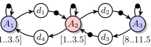
Figure 12: Dataflow model of Figure 10 with the proposed extensions.
new response time of taskTi which in our case will be the
maximum execution time of task including the scheduler
in-terference. Ciis the WCET, andBithe maximum blocking
time of taskTi. The blocking time will be zero because no
lower priority tasks are present, and the WCET of a task
is known. hp(i) are all higher priority tasks, which in this
case is only the task modeling the scheduler interference. The equation can thus be simplified to the equation shown
in Eq. 2, where Tsched is the tick-period, and Csched the
maximum execution time of the scheduler.
Rin+1=Ci+
⌈
Rn i
Tsched
⌉
Csched (2)
5.2.2
Input delay
With the tick-based FPP scheduler a release of a container does not immediately trigger the response of the scheduler.
This can be seen in Figure 11, where the release of T2 is
processed byP1 3 time-units after the task finished. This
delay between release and acquire is only present if tasks are scheduled on different processors, because it is guaranteed that an enabling operation will always follow a release oper-ation on a processor. First, minimum and maximum of the delay will be derived, after which it will be shown how the delays can be incorporated in the dataflow model.
The minimum amount of delay an input could experience is zero. This happens if a processor releases a container just before the enabling operation of the scheduler on the receiv-ing processor. The maximum delay happens if a container is released just after the enabling operation of the receiving scheduler. The worst-case situation is then if a complete tick period passes, and the task on the receiving processor fin-ishes resulting in a release operation. The maximum bound on the additional delay to the input is then equal to the tick-period plus the WCET of a release operation of the scheduler on the receiving processor. The subsequent enabling oper-ation of the scheduler will not have to be included, as this operation is already accounted for in the firing duration of the actor.
The delay of the inputs means that a task can only ac-quire a container some time after the release of a container. This delay can be modeled by an actor on the edge between actors on different processors. The actor should have a max-imum firing duration equal to the maxmax-imum delay explained in the previous paragraph. The delay between release and acquire of tasks does not cost any processing cycles of the processors, therefore the delay actor should not be bound to any processor, and is allowed to execute auto-concurrently in the dataflow model.
5.2.3
Extended model
T4 [5]
T2 [10]
T5 [5]
T1 [5]
[image:8.595.119.225.53.119.2]T3 [10] src
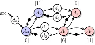
Figure 13: The case-study task graph
A4 [6] d5 src
A5 [6] A2
[11]
A1 [6]
A3 [11] d1
d2 d3
d4
Figure 14: Extended dataflow model of the task graph.
account for the scheduler interference. Therefore equation 2 is used whereTj= 5andCen= 0.4. The results are3.5and
11.5for the tasks with a WCET of respectively 3 and 10.
Furthermore, delay actors have to be added on the edges of tasks on different processors. This is modeled in the dataflow model as actors with different colors. From Fig-ure 9 it can be concluded that an extra actor has to be added on four edges. The firing duration of these actors was the tick-period plus the WCET of the enabling operations,
which is equal to 5 + 0.5 = 5.5 time-units. The resulting
dataflow model is shown in Figure 12.
6.
CASE STUDY
In this section, the results will be discussed of simulating an example task graph in the event-driven simulator HAPI [15]. The task set was scheduled using the tick-based FPP scheduler, and a non-tick based FPP scheduler. The ob-served finish times of the simulations have been compared with the derived maximum finish times using a dataflow model.
The example task graph is depicted in Figure 6. The WCETs of the tasks are depicted between brackets, and are excluding the preemption costs of 1 time-unit. All the FIFO buffers have a size of one, and are initially empty. The buffers can thus be modeled in a dataflow model using two edges and one token on the edge towards the producing task. All acquires and releases are assumed to cost zero time, but they can be non-atomic. Furthermore, servicing interrupts is assumed to cost zero time, the arrival rate of interrupts will therefore not have to be bounded.
The tick-based FPP schedulers on both processors will have a tick-period of three time-units, and the enabling and release operations have a WCET of 0. The delays intro-duced by the tick-based scheduler can now be incorporated in the dataflow model of the application. The firing du-rations of the actors are first extended with a preemption cost. Then the interference due to the enabling operation of the scheduler can be included using Eq. 2. As the enabling phase takes zero time, the interference will be zero and the maximum firing durations will not be extended. Next, a delay actor will be added on every edge between actors on
Table 1: The maximum and measured finish times.
T1 T2 T3 T4 T5
non-tick based simulation 38 16 32 16 38analysis 18 17 29 6 12
tick-based simulation 26 18 30 8analysis 29 20 35 9 1814
different processors. These delay actors have a maximum
firing duration of3 + 0 = 3. The resulting dataflow graph
is shown in Figure 6. In order to increase the clarity of the graph, the self-loop of actors have been omitted, but all actors modeling a task have an implicit self-loop with a token.
From the task graph depicted in Figure 6, an equivalent dataflow model can be derived by adding preemption costs to the WCET, and modeling the buffers as two edges. Using the execution intervals of the actors the maximum finish times will be derived [14]. These include delays due to the FPP scheduler. The same dataflow analysis techniques will be applied on the extended dataflow graph to determine the maximum finish times if the task set is scheduled with the tick-based FPP scheduler. The obtained bounds are depicted for the actors in Table 1 in the analysis rows.
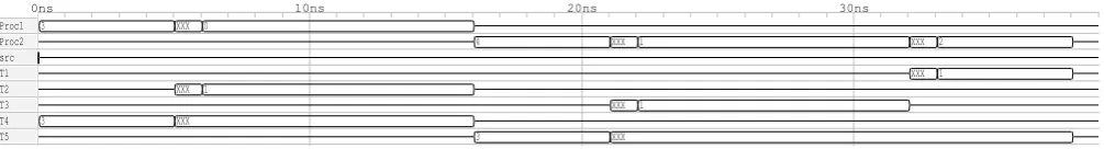
The traces, obtained with the HAPI simulator, of the pro-cessors and tasks are shown in Figure 15 for the non-tick based FPP scheduler, and Figure 16 for the tick-based FPP scheduler. Preemption overhead and blocking are shown in the figures as X’s.
Figure 15 shows that with the non-tick based FPP sched-uler all executions happen sequentially. Although two cessors are available, the non-atomic releases cause all pro-cessing to happen sequentially. Non-atomic releases cause
in this trace interference for example after 5 ns, where T4
releases a container forT2 which immediately causes a
pre-emption. TaskT4 is because of this only able to release the
containter forT5after 15 ns. A similar situation happens
af-ter 21 ns, where the execution ofT5is first preempted byT3,
and then byT1 causing the finish ofT5 to be delayed untill
38 ns. The measured finish times of this execution trace are also shown in Table 1 in the simulation row. Clearly. the analysis derived invalid conclusions for tasksT1,T3,T4 and
T5, as the finish times from this simulation are later then
the presumed maximum finish times. Non-atomic acquires and releases are thus able to cause optimistic finish times derived through dataflow analysis.
The simulated execution trace of the tick-based FPP sched-uler depicted in Figure 16 shows that with this schedsched-uler part of the executions happen concurrently. The scheduler is thus better able to exploit the two processors. In the fig-ure it can clearly be seen that due to polling the start of tasks can be delayed. This can for example be seen by the
delayed start ofT4, which starts nearly three time-units
af-ter the finish of the source. Also taskT5 has to wait on the
end of a tick period before the released container ofT4is
[image:8.595.89.254.156.234.2]3 XXX 0
4 XXX 1 XXX 2
XXX 1 XXX 1
XXX 1
3 XXX
3 XXX
Proc1 Proc2 src T1 T2 T3 T4 T5
[image:9.595.55.558.52.120.2]0ns 10ns 20ns 30ns
Figure 15: Trace of Figure 6 if scheduled by a non-tick based FPP scheduler
2 4
3 0 XXX 1 0
XXX 2 2
1 XXX 1
3
3 Proc1
Proc2 src T1 T2 T3 T4 T5
0ns 10ns 20ns 30ns
Figure 16: Trace of Figure 6 if scheduled by the tick based FPP scheduler
7.
FUTURE WORK
This paper presented a scheduler that avoids interferences due to non-atomic releases and acquires. Surrounding this scheduler, there are some open questions regarding alter-natives, implementation and analysis which will have to be answered in future research.
The finish times derived for the tick-based FPP scheduler using dataflow analysis are only tight if the delays modeled by the extra actors are also present in the execution trace. A design where releases happen at the right times means that delays due to polling are removed and the finish times derived using dataflow analysis will be overestimations of the actual worst-case. Future research can focus on trying to identify where the delay actors might be overestimations, thereby tightening the maximum finish time derivations.
At this moment, the tick-based scheduler keeps executing periodically, even if no new containers were received. This wastes power, as no relevant executions are done, and causes late finish times because the processor might be idling while a task could be enabled. On an architecture with interrupts it might be possible to allow interrupts only if the processor is idling. This ensures quick responses to incoming events, and removes the need for a period check while idling.
The tick-based FPP scheduler has not been implemented yet on an architecture. Therefore, there are no real measure-ments of the delays introduced by the proposed scheduler, and its feasibility was only tested in simulations. An imple-mentation of the scheduler on an architecture such as the Starburst would enable measurements of the interference of the enabling operation, and give means to test the analyti-cally obtained bounds using real-world applications.
The tick-based scheduler was primarily developed because of its applicability on the Starburst architecture, where pro-cessors have no means to communicate other than through shared memory. Solving the issues of non-atomic acquires and releases can be done using other schedulers. A solu-tion that seems promising is temporarily ignoring interrupts while releasing containers, while enabling tasks only if all inputs are available. This solution requires an IC, as the in-terrupts have to be serviced, but does not have the polling delay that the tick-based FPP scheduler has. Especially if processors have low-utilization, dataflow analysis might be able to derive tighter maximum finish times.
8.
CONCLUSION
In this paper we presented a tick-based FPP scheduler for which pessimistic finish times can be determined for a task graph using existing dataflow analysis techniques. The fin-ish times are pessimistic even if consumptions happen atomically at the beginning and productions happen non-atomically at the end of a task’s execution. Furthermore, the scheduler polls for data such that the arrival rate of incoming events does not have to be bounded.
The proposed FPP scheduler removes interferences expe-rienced by tasks due to non-atomic acquires and non-atomic releases at respectively the start and end of the execution. This is realized by enabling tasks only if all their inputs are available, and ensuring all releases happen without interfer-ence from the scheduler. Finally, the arrival rate of data transfers does not have to be bounded to ensure that a task set is deadlock free. This is because the scheduler is not triggered by an interrupt accompanying the data transfer, but polls the buffers periodically.
Delays introduced by the scheduler can be captured by extensions to the dataflow model of the application. Periodic execution of the scheduler can be added to the dataflow model by extending the firing durations with the maximum interference by the scheduler, and delays due to the periodic check can be included using additional actors. With these additions existing dataflow analysis techniques are able to determine pessimistic finish times for the task set modeled by the dataflow model.
The case study verified that tasks with non-atomic ac-quires and releases can experience interferences not accounted for in the dataflow model. Due to these interference the conclusions derived using dataflow analysis can be false if a non-tick based FPP scheduler is used. The simulations of the task set using a tick-based scheduler confirm the pessimism of the finish times derived using the extended dataflow model. Dataflow analysis is thus able to derive valid conclusions if the tick-based FPP scheduler is used, even if acquires and releases happen non-atomically.
References
static priority pre-emptive scheduling. Software Engi-neering Journal, 8(5):284–292, 1993.
[2] N. C. Audsley, I. J. Bate, and A. Burns. Putting fixed priority scheduling theory into engineering practice for
safety critical applications. In Real-Time Technology
and Applications Symposium, 1996. Proceedings., 1996 IEEE, pages 2–10, Jun 1996.
[3] R. J. Bril, J. J. Lukkien, and W. F. J. Verhaegh. Worst-case response time analysis of real-time tasks under fixed-priority scheduling with deferred preemption
re-visited. In 19th Euromicro Conference on Real-Time
Systems (ECRTS’07), pages 269–279, July 2007.
[4] A. Burns, K. Tindell, and A. Wellings. Effective analysis for engineering real-time fixed priority
sched-ulers. Software Engineering, IEEE Transactions on,
21(5):475–480, 1995.
[5] A. Burns, A. J. Wellings, and A. Hutcheon. The impact of an ada run-time system’s performance characteristics
on scheduling models. In Ada-Europe’93, pages 240–
248. Springer, 1993.
[6] G. Buttazzo. Hard real-time computing systems:
pre-dictable scheduling algorithms and applications, vol-ume 24. Springer Science & Business Media, 2011.
[7] G. C. Buttazzo, M. Bertogna, and G. Yao. Limited preemptive scheduling for real-time systems. a survey. industrial Informatics, IEEE Transactions on, 9(1):3– 15, 2013.
[8] B. H. J. Dekens, P. S. Wilmanns, G. J. M. Smit, and M. J. G. Bekooij. Low-cost guaranteed-throughput dual-ring communication infrastructure for
heteroge-neous MPSoCs. InDesign and Architectures for Signal
and Image Processing (DASIP), 2014 Conference on, pages 1–8, Oct 2014.
[9] R. Gopalakrishnan and G. M. Parulkar. Bringing real-time scheduling theory and practice closer for
multi-media computing.SIGMETRICS Perform. Eval. Rev.,
24(1):1–12, May 1996.
[10] J. P. Hausmans, M. H. Wiggers, S. J. Geuns, and M. J. Bekooij. Dataflow analysis for multiprocessor systems
with non-starvation-free schedulers. InProceedings of
the 16th International Workshop on Software and Com-pilers for Embedded Systems, M-SCOPES ’13, pages 13–22. ACM, 2013.
[11] D. I. Katcher, H. Arakawa, and J. K. Strosnider.
Engi-neering and analysis of fixed priority schedulers.
Soft-ware Engineering, IEEE Transactions on, 19(9):920– 934, 1993.
[12] H. Kopetz. Operating Systems of the 90s and
Be-yond: International Workshop Dagstuhl Castle, Ger-many, July 8–12 1991 Proceedings, chapter Event-triggered versus time-Event-triggered real-time systems, pages 86–101. Springer Berlin Heidelberg, Berlin, Heidelberg, 1991.
[13] G. Kuiper, S. J. Geuns, and M. J. G. Bekooij. Utiliza-tion improvement by enforcing mutual exclusive task execution in modal stream processing applications. In Proceedings of the 18th International Workshop on Soft-ware and Compilers for Embedded Systems, SCOPES ’15, pages 28–37, New York, NY, USA, 2015. ACM. [14] P. S. Kurtin, J. P. Hausmans, and M. J. Bekooij.
Com-bining offsets with precedence constraints to improve temporal analysis of cyclic real-time streaming
applica-tions. In2016 IEEE Real-Time and Embedded
Technol-ogy and Applications Symposium (RTAS), pages 1–12. IEEE, 2016.
[15] P. S. Kurtin, J. P. Hausmans, and M. J. Bekooij. HAPI: An event-driven simulator for real-time multiprocessor systems. M-SCOPES ’16, New York, NY, USA, 2016. ACM.
[16] J. J. Labrosse.µC/OS-iii User’s Manual. Micriµm, 3.05
edition, 2015.
[17] A. Lele, O. Moreira, P. J. Cuijpers, and K. van Berkel. Response modeling runtime schedulers for timing
anal-ysis of self-timed dataflow graphs. Journal of Systems
Architecture, 65:15 – 29, 2016.
[18] C. L. Liu and J. W. Layland. Scheduling algorithms for multiprogramming in a hard-real-time environment. Journal of the ACM (JACM), 20(1):46–61, 1973. [19] T. Pop, P. Eles, and Z. Peng. Schedulability analysis
for distributed heterogeneous time/event triggered
real-time systems. InReal-Time Systems, 2003. Proceedings.
15th Euromicro Conference on, pages 257–266. IEEE, 2003.
[20] O. Redell and M. Torngren. Calculating exact worst case response times for static priority scheduled tasks
with offsets and jitter. In Real-Time and Embedded
Technology and Applications Symposium, 2002. Pro-ceedings. Eighth IEEE, pages 164–172, 2002.
[21] K. W. Tindell, A. Burns, and A. J. Wellings. An ex-tendible approach for analyzing fixed priority hard
real-time tasks. Real-Time Systems, 6(2):133–151, 1994.
[22] Vector Corporation. OSEK/VDX Operating System,
2.2.3 edition, Feb 2005.
[23] M. H. Wiggers, M. J. G. Bekooij, and G. J. M. Smit. Modelling run-time arbitration by latency-rate servers
in dataflow graphs. InProceedingsof the 10th
Interna-tional Workshop on Software &Amp; Compilers for Em-bedded Systems, SCOPES ’07, pages 11–22, New York, NY, USA, 2007. ACM.
[24] P. S. Wilmanns, J. P. Hausmans, S. J. Geuns, and M. J. Bekooij. Accuracy improvement of dataflow analysis for cyclic stream processing applications scheduled by
static priority preemptive schedulers. InDigital System
Design (DSD), 2014 17th Euromicro Conference on, pages 623–630. IEEE, 2014.
[25] G. Yao, G. Buttazzo, and M. Bertogna. Comparative
evaluation of limited preemptive methods. InEmerging