Abstract—Since the complexity of electrical system has been aggravated as the deep-submicron technology in chip manufacturing continuously develops, chips are far more likely to be affected by various faults. Effective on-line testing method is a great challenge for high reliability system design. We propose a novel test structure based on Software Based Self-Test (SBST) to implement on-line test with low overhead.
This test structure adopts a microprocessor to apply test stimulus, analyze test response and manage the test process.
The microprocessor should define the specific test instructions and primarily accomplish the self-test for verification its own function. Test vectors of some modules are generated by TetraMAX for achieving high fault coverage and reducing area overhead. The on-line test results of a LVDT module for avionics control system show the efficiency and flexibility of proposed test scheme.
Index Terms—SBST, On-line Test, CPU Self-Test, ATPG
I. INTRODUCTION
ITH the continuous development of semiconductor technology, greater demands are being placed on the overall performance of electronic systems. In order to improve the reliability and stability of electronics systems, especially for secure-sensitive application such as avionics control system, efficient test methods are urgently needed for maintenance. The traditional off-line test methods are liable to detect the permanent faults statically, while hardly can detect transient faults or errors that may occur on the function mode. This scenario will be fatal for fault-sensitive electronic system. Another test method utilizes automated test equipment (ATE) based on computer information processing and built-in self-test (BIST) test structure [1]. However, this method needs to modify the original structure of the circuit and increases the area of the circuit, which may affect the
Manuscript received March 20, 2018; revised April 8, 2018. This work was supported in part by the National Natural Science Foundation of China (No. 61701228 and 61106029), the Aviation Science Foundation of China (No. 20162852028 and 20152052025) and the Fundamental Research Funds for the Central Universities (No. NS2015045 and NS2016046).
Z. F. Jin is with the College of Electronic and Information Engineering, Nanjing University of Aeronautics and Astronautics, Nanjing, Jiangsu Province, 211106 CHINA (e-mail:[email protected]).
Y. Zhang is with the College of Electronic and Information Engineering, Nanjing University of Aeronautics and Astronautics, Nanjing, Jiangsu Province, 211106 CHINA (phone: 86-25-84892381; fax: 86-25-84892452;
e-mail: [email protected]).
X. Chen is with the College of Electronic and Information Engineering, Nanjing University of Aeronautics and Astronautics, Nanjing, Jiangsu Province, 211106 CHINA (e-mail: [email protected]).
F. Ge is with the College of Electronic and Information Engineering, Nanjing University of Aeronautics and Astronautics, Nanjing, Jiangsu Province, 211106 CHINA (e-mail: [email protected]).
performance of the whole system. Moreover, the cost of ATE is quite high.
Meanwhile, embedded processor is adopted by most designers in the design of integrated circuits. As the technology of chip processing advances, delay faults of wires and the incompleteness of signals are more likely to occur.
Some of the faults will only be activated when the circuit is running at full speed. For typical ATE and BIST scheme, more expensive and faster test equipment is required. These technical challenges of test have aroused the research on new test methods to test processors or controllers over the past decade. The method called Software Based Self-Test (SBST) adopts the processor’s instruction set to test the processor. In recent years, functional testing based on SBST has been presented as a suitable solution to the problem of test generation for complex VLSI systems, such as microprocessors [2]. Shen and Abraham [3] developed a tool called Vertic which is able to generate test programs. They applied it on GL85 processor and proved the high efficiency of SBST for the first time. Then Parvathala, et al [4] proposed an automatic function self-testing method called Frits which is able to generate random instruction sequences.
Gurumurthy, et al [5] developed an instruction generation technique for faults that are hard to be detected. They also utilized ATPG tools to help generate test vectors.
These proposed SBST schemes focus on the self-test of the processor. In addition, on-line testing is also an effective method to capture operational faults, detect the transistor aging, and improve the system reliability [6]. So we apply SBST to the on-line test of module circuits besides processor for an avionics controller. We propose a test structure based embedded MIPS processor with high fault courage and low overhead. When the processor functions normally, it will implement on-line testing for circuits under test by executing prepared test programs stored in embedded RAM. Also the processor is able to analyze and store the test responses on-line. Test vectors can be generated by LFSR circuits or ATPG tools. Considering the modular construction of proposed test scheme, it will be adaptable for other fault-sensitive system on-line test.
The rest of the paper is organized as follows. Section II describes the design of on-line test system. We proposed the implement of on-line test for avionics controller in Section III.
Section IV provides the experiments results of on-line test.
Finally, the paper is concluded.
II. THE ARCHITECTURE OF ON-LINE TEST SYSTEM The Software Based Self-Test (SBST) is applying the programmable resources on the chips to execute the normal programs to achieve the purpose of testing the processor and
A Novel On-Line Test Scheme for Avionics Controller Based on SBST
Jin Zhengfei, Zhang Ying, Chen Xin, and Ge Fen
W
peripheral functional modules. The processor employs original instruction sets to generate and load test vectors, which eliminates the requirement of additional hardware for testing. At the same time, the test programs are executed at the normal operating frequency of the processor, which will meet the requirement of real-time on-line testing.
The typical SBST test process for microprocessor consists of four parts:
1) The developers will design test programs and generate test vectors for test and diagnosis according to the circuit under test;
2) The test programs and test data will be downloaded to the processor’s memory;
3) The processor executes the test programs at full speed.
These programs execute appropriate instructions to achieve the same effect as activating faults by test vectors;
4) The test response is analyzed by processor online or uploaded to the storage area.
In order to implement the on-line test structure proposed by this paper, a microprocessor is needed as a control module for the whole test procedure. MIPS (Microprocessor without Interlocked Piped Stages) is based on the reduced instruction set architecture [7]. It has relatively simple structure and supports pipeline execution, so it is capable of fulfilling parallel assignments. Due to the above features, we employ the 16-bit MIPS microprocessor as the CPU in proposed SBST scheme.
The upper part of Fig. 1 shows the structure of MIPS microprocessor we apply. It can be seen that the MIPS processor is based on Harvard architecture and it has a five-stage pipeline. The five units are fetch unit, decoder unit, execution unit, memory accessing unit and write back unit.
The function of each unit is explained as follows:
1) Fetch unit: This unit reads instructions from ROM which storing instructions.
2) Decoder unit: This unit parses the instructions transmitted from the fetch unit.
3) Execution unit: This unit executes operations according to the instruction.
4) Memory accessing unit: This unit is responsible for reading or writing RAM.
5) Write back unit: This unit is used to write data back to register.
This microprocessor has a total of 8 16-bit general registers named as R0~R7. In particular, register R0 has a special characteristic that no matter what data is written to register R0, the data read from register R0 is always 0.
The length of each instruction is 16 bits and the instructions executed in on-line test structure can be divided into the following categories as Table I shows.
Fig. 1 shows the architecture of the on-line test system based on SBST. It can be seen that the system consists of three parts which are the MIPS microprocessor, the bus
controller and the target circuit. The MIPS microprocessor is responsible for generating test vectors, applying test vectors on target circuit, collecting test response and online analysis of the test response. The key design is to set up a data path and a control path between the MIPS microprocessor and target circuit, so that the MIPS microprocessor can accomplish the whole test process of the circuit under test.
When the MIPS microprocessor is accessing memory, the address width is 16 bits. But in fact RAM only needs 8-bit address width and the first 8 bits are 0. Considering that we have different modules to be tested, we can make use of the first 8 bits to decide which module to be tested. Table II lists the example of decoded test targets by the first 8 bits address.
According to the instructions, the bus controller chooses the modules and transmits data and signals between the microprocessor and the module. On the basis of the signal width required by the circuit under test, the bus controller configures the data transferred from microprocessor according to the circuit under test. For example, if we have to configure 32 bits of data to execute a test operation while the data width of the microprocessor is 16 bits, then we need to configure 2 instructions at a time. So we design an identification number for the circuit to be tested. The identification number is generated by microprocessor and only the correct number can activate the corresponding test application. When the test process is activated, the identification number may be 0 or 1. If the number is 0, the bus controller receives the first 16-bit data. On the contrary, the bus controller receives the last 16-bit data. After two times of configuration, the bus controller will send the whole 32-bit data to the circuit. Similarly, the response date will be stored in the registers of bus controller temporarily and wait for the microprocessor to fetch the data. The logic to fetch data can also be designed according to the requirement of data width. The configuration process can be adjusted
Fig. 1. The structure of the whole test system TABLEI
INSTRUCTIONS CATEGORY
Category Instructions
Memory Access LD, ST
Operation ADD, ADDI, SUB, XOR…
Branch Jump BZ
TABLEII
THE CIRCUITS REPRESENTED BY THE FIRST 8 BITS ADDRESS
Address Target Circuit
8’b00000001 Memory
8’b00000011 Multiplier
8’b00000111 IIR Filter
8’b00001111 Controller
through the modification of processor program, which contributes the flexibility of proposed test structure.
The circuit under test in this paper is a part of an LVDT (Linear Variable Differential Transformer) system. The LVDT is a linear displacement transducer which has many advantages such as high accuracy, wide linear range and excellent repeatability. So it is widely applied to measure displacement, speed and acceleration [8]. As a terminal to acquire information for aero engine controller, the LVDT demodulation circuit is a prerequisite for stable, accurate and fast processing, decision and feedback of the control system.
It is composed of four modules including an IIR filter, two 32-bit multipliers and a high-speed dual-port RAM with a width of 16 bits and a depth of 256 bits. The testing process of these circuits will be described in detail in next section.
III. IMPLEMENT OF ON-LINE TEST
The whole testing process based on SBST is divided into two parts: the first part is the self-test of MIPS microprocessor, and the second part is the test of other modules in LVDT circuit.
A. Test for MIPS
The MIPS microprocessor controls the process of the test system and is the core module of SBST. So it is necessary to test the microprocessor to guarantee the completeness and correctness of the test system.
Above all, we divide the MIPS microprocessor into 4 parts:
memory, ALU, register group and pipeline. According to the functions and characteristics of each module, we adopt relevant test programs for different modules based on the instruction set of the MIPS microprocessor. Then, we will introduce the test program for each module to realize the self-test of microprocessor.
1) Memory
We employ the March C+ algorithm to test RAM. The March C+ algorithm is based on March C algorithm and it adds a read operation to the original design. Compared with March C algorithm, the March C+ algorithm can be used to test stuck-open fault and the fault coverage of the March C+
algorithm for RAM is over 95% [9]. In addition, the March
C+ algorithm can detect stuck-at faults, transition faults, address decoder faults, coupling faults and neighborhood pattern sensitive faults of decoder circuit, memory data register and memory address register.
The March C+ algorithm is represented by the element symbol as b(w0) ↑(r0,w1,r1) ↑(r1,w0,r0) ↓(r0,w1,r1) ↓ (r1,w0,r0) ↓(r0) [10]. The character b means choosing ascending or descending order randomly, w means writing, r means reading, ↑ means ascending order, and ↓ means descending order.
When executing test program, the MIPS microprocessor will read and write all memory cells in ascending order or descending order according to the test program based on March C+. By comparing the data written to RAM and read from RAM, the MIPS microprocessor is able to judge which memory cell has a fault.
2) ALU
The ALU occupies a considerable proportion of the hardware space of the microprocessor and has a higher contribution to the fault test coverage. Also, the SBST method needs the ALU to execute right operations to guarantee the correctness of test. Therefore, the test of ALU is an important part of the self-test of the microprocessor.
The ALU of the MIPS microprocessor has 8 kinds of operation which are ADD, SUB, AND, OR, XOR, SL, SR and SRU. The inputs of ALU are two16-bit numbers named a and b. The output is a 16-bit number named r.
We take operation ADD as an example. The assembly code designed to test operation ADD is “ADD R3, R1, R2, 0”.
We need 3 groups of test stimulus and Table III shows the test stimulus and ideal response. During the process of testing, the microprocessor will compare the value of register R3 with the ideal response to judge whether the circuit is working normally.
3) Register Group
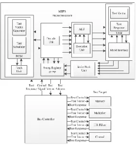
The test data of SBST are stored in registers and the test program designed to test registers is divided into 2 parts. In each part, half of the registers are in the test mode while another 8 registers are used to control the test execution. By taking such measures, we can use all the 8 registers of the microprocessor during the test without adding additional hardware resources. The test program presented in the form of pseudocode is showed in Fig. 2.
In the initialization stage, we need to assign different values to registers with one encoding range, so we can detect stuck-at faults when executing read or write operation. After the initialization, the microprocessor should execute some instructions to activate all the data path of register group. Part of the assembler commands are as follows:
[1]XOR R5 = R0, R1 XOR R6 = R2, R3 [2]XOR R5 = R1, R0 //part 1
Assign values to R0, R1, R2 and R3
For each register R(R belongs to R0, R1, R2 and R3):
For each read port P:
Read V (the value of register) from read port P;
Generate a sign S according to V;
On-line diagnosis;
Save the Diagnostic information.
//part 2
Assign values to R4, R5, R6 and R7
For each register R(R belongs to R4, R5, R6 and R7):
For each read port P:
Read V (the value of register) from read port P;
Generate a sign S according to V;
On-line diagnosis;
Save the Diagnostic information.
TABLEIII TEST FOR OPERATION ADD
Operation Test Incentive a
Test Incentive b
Ideal Response r ADD 1010101010101010 0101010101010101 1111111111111111 ADD 0101010101010101 1010101010101010 1111111111111111 ADD 0000000000000000 0000000000000000 0000000000000000
Fig. 2. Test program for register group
XOR R6 = R3, R2
R0 is the first operand in the first part, but in the second part R0 is the second operand. The two instructions seem similar, but in fact the value of R0 is read from two different read ports of the register. So that, all the data paths accessible to register group will be tested. By comparing the values of R5 and R6 with ideal response, the microprocessor can verify whether there are faults in the circuit.
4) Pipeline
The traditional development of SBST method focuses on the function modules of the microprocessor and ignores the test of pipeline unit. Actually, the average fault coverage of function modules can be more than 90%, while the fault coverage of pipeline unit is lower than 80%. Although the logic of pipeline occupies relatively small hardware size, it is critical to guarantee the microprocessor function. So we design a test program specially to test the processor’s pipeline.
The fault of pipeline is related to data dependency of the overlap instructions. Providing the assumption that instruction b is executed after instruction a, instruction b should read the value of certain register only after a finishes the write operation on it. Otherwise, it will cause the function error and this data dependency is defined as the read-after-write hazard. Some hazards can be solved by sending the address information to the decoder unit in advance (forward path method). For other unsolved hazards, the following instruction execution will suspend until the write operation finishes.
To verify the function of pipeline, we should firstly find out all the hazards that can be solved or cannot be solved.
Secondly, we should activate all the conditions which may suspend the pipeline. Thirdly, we should activate all the different forward paths to the pipeline level, and confirm whether the design of pipeline functions normally.
B. Test for LVDT modules
As the test of microprocessor, we divide the circuits into two parts. One is memory which belongs to general module like RAM and the other is special modules such as IIR Filter.
1) Memory
We test the RAM of target circuit still by using the March C+ algorithm. The process of test is the same as the test of MIPS’s RAM.
2) IIR Filter
Like the other modules, the SBST needs test programs to detect faults of IIR Filter. However, the IIR Filter is not a general logic circuit, and it is relatively difficult to find an efficient algorithm to design test programs for this kind of circuit. There are mainly two ways to generate test vectors for integrated circuit. One adopts linear shift register to generate pseudorandom test vectors and the other applies ATPG (Automatic Test Pattern Generation) algorithms to generate test vectors. The number of pseudorandom test vectors increases exponentially with the expansion of the test scale while the ATPG algorithm can reach high fault coverage with less test vectors. So we employ the software called TetraMAX to generate test vectors for special modules. The MIPS microprocessor will be in charge of imposing the test vectors.
The IIR Filter is tested by inserting scan chains and applies
Synopsys's DFT Compiler and TetraMAX for testing development. DFT Compiler replaces the ordinary register in the circuit with the shift register which supports the function of scanning, and these shift registers increase the controllability and observability inside of the circuit.
To design test program for the special module under test, we adopt the following test process:
First of all, we should import the circuit’s Verilog file into DFT Compiler. Then DFT Compiler will analyze the internal structure of the circuit. After that, the software will set test constraints and replace ordinary registers with shift registers.
At last, it will output the netlist file and test constraint file of the circuit which has been inserted scan chains.
Secondly, we should import the netlist file and test constraint file generated by DFT Compiler into TetraMAX, then set up the ATPG model of the circuit. Next, we should set up the type and format of the test vector and the ATPG tool will generate the test vector file.
Thirdly, the test vectors generated by the TetraMAX will be applied on the VCS software platform for simulation to ensure the reliability of the test vectors.
Finally, we will design test programs according to the tested vectors which are validated.
Scan design is a testability method which is widely applied, and it is proposed for complex sequential circuit testing. The general scan design only inserts one or several scan chains, so each scan chain has several scan registers, and the input and output of data need to be transmitted in series. In order to simplify the design of the bus controller and make full use of the parallelism of microprocessor, we set up 22 scan chains for IIR filter which has 22 scan registers in all. So each scan chain has only 1 register and all the inputs and outputs of registers will be parallel, which decreases the testing time and simplifies the test control logic.
The parameter of two means to insert scan chains is shown in Table IV, which proves that inserting n scan chains greatly shortens the time of register configuration. As a result, the total test time is shortened.
IV. EXPERIMENTAL RESULTS
The hardware simulation platform adopted in our study is Xilinx Kintex-7 development board. The software platforms are ModelSim, Xilinx’s ISE, Synopsys's Design Complier and TetraMAX. We employ ModelSim and ISE to emulate Verilog codes and Synopsys's EDA software to insert scan chain (DFT Compiler), generate test vectors (TetraMAX) and verify simulation results (VCS).
A. Self-test of MIPS microprocessor’s RAM
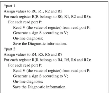
According to the March C+ algorithm, we design the test program for RAM and implement hardware simulation on FPGA. The signals captured by Chipscope from FPGA are showed in Fig. 3. This picture shows one operation (read 0, write 1 and read 1) of March C+ algorithm for one memory
TABLEIV
COMPARISON OF 1 SCAN CHAIN AND N SCAN CHAINS
Test Module (IIR Filter)
Test Time /clock cycle
1 scan chain 560
n scan chains
(n=22) 140
cell. Signal mem_write_en controls the reading and writing of RAM. Signal ex_alu_result is responsible for memory address. Signal mem_read_data shows data which are read from RAM. Signal mem_write_data provides data to be written to RAM. Initially, ex_alu_result sends read address BA46h. In the next clock cycle, the microprocessor reads data 0000h from the address. Then, the microprocessor pulls up enable signal mem_write_en. Signal mem_write_data sends the data FFFFh and ex_alu_result sends the write address BA46h. The data is written to RAM. Finally, signal ex_alu_result sends read address BA46h and the data read from the address is FFFFh as the signal mem_read_data shows. The waveform of Fig. 4 is consistent with the algorithm flow and verifies the validity of the simulation. So the test program of March C+ is proved to be correct.
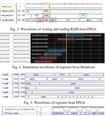
B. Self-test of MIPS microprocessor’s register group The simulation waveform of register group from ModelSim and FPGA are separately showed in Fig. 4 and Fig. 5. We assign values to reg_array0, reg_array1, reg_array2 and reg_array3. The microprocessor will firstly calculate the value of reg_array0 XOR reg_array1 and store the value to reg_array6. Then the microprocessor will calculate the value of reg_array2 XOR reg_array3 and store the value to reg_array7. Finally, the microprocessor will compare the value of reg_array6 and reg_array7 by XOR gate. If these two values are equal, the circuit being tested has no fault.
Because the simulation waveform and real waveform are the same, the test program realizes the proposed function.
C. Self-test of MIPS microprocessor’s pipeline
Under normal circumstances, the signal pipeline_stall_n remains at 1. When the microprocessor’s hazard_detection module is activated, the pipeline_stall_n will be pulled down.
And the signal pc represents the instruction that the microprocessor is executing. In order to test pipeline, we must activate the function of the pipeline logic. Fig 6 shows the waveforms of pipeline_stall_n and pc captured by
Chipscope from FPGA. As shown in the Fig. 6 that when pc is 02h, 06h, 08h and 0Bh, signal pipeline_stall_n is 0 and the microprocessor will delay certain time to execute the instruction. In other cases, pipeline_stall_n is 1 and instructions are executed normally according to the clock frequency. The waveforms show that in the former case, the hazard_detection module is activated correctly and functions normally. So the pipeline test program is able to achieve the goal.
D. Test Results of Target Circuits
Fig 7 shows the test report of IIR Filter generated by TetraMAX. It can be seen that the ATPG tool generates 20 test vectors for a total of 630 faults and the test coverage is 100%. Fig 8 shows the test report of control module generated by TetraMAX. The ATPG tool generates 74 test vectors for a total of 1416 faults and the test coverage is also 100%.
V. CONCLUSION
The SBST method will be a trend in integrated circuit testing because the increase of the circuits complexity and the need of at-speed testing. This paper proposes a novel on-line test structure based on SBST. We apply the SBST method which is usually used to processor self-test to the test of avionics controller circuits. In the proposed SBST structure, a
Fig. 7. Test Report of IIR Filter
Fig. 4. Simulation waveforms of registers from Modelsim
Fig. 5. Waveforms of registers from FPGA Fig. 3. Waveforms of writing and reading RAM from FPGA
Fig. 6. Waveforms of pipeline from FPGA Fig. 8. Test Report of IIR Filter
MIPS microprocessor is employed to automatically execute test programs, collect and analyze test response on-line. To implement on-line test based on SBST, we design matched test programs for each module of the avionics controller. For some specific module, we insert n scan chains by EDA tools and adopt ATPG tool to generate test vectors for improving the test efficiency. The emulation results show that the on-line test architecture based on SBST is efficient and has high portability that can be applied to other electronic systems.
REFERENCES
[1] Jervan G, Eles P, Zebo Peng, et al. “Hybrid BIST time minimization for core-based systems with STUMPS architecture”. Proc. of IEEE International Symposium on Defect and Fault Tolerancein VLSI Systems, 2003, pp. 225–232.
[2] Ján Hudec. “An Efficient Adaptive Method of Software-Based Self Test Generation for RISC Processors”. 4th Eastern European Regional Conference on the Engineering of Computer Based Systems, 2015, pp.
119-121.
[3] J. Shen, J.A. Abraham. “Native Mode Functional Test Generation for Processors with Applications to Self-Test and Design Validation”.
Proceedings International Test Conference, 1998, pp. 990–990.
[4] P. Parvathala, K. Maneparambil, W. Lindsay. “FRITS: A Microprocessor Functional BIST Method”. Proceedings International Test Conference, 2002, pp. 590~598.
[5] S. Gurumurthy, S. Vasudevan, J. A. Abraham. “Automatic Generation of Instruction Sequences Targeting Hard-to-Detect Structural Faults in a Processor”. Proceedings International Test Conference, 2006, pp.
776–784.
[6] Ching-Wen Lin, Chung-Ho Chen. “Processor shield for L1 data cache software-based on-line self-testing”. 22nd Asia and South Pacific Design Automation Conference, 2017, pp. 420-425.
[7] Agineti Ashok, V. Ravi. “ASIC Design of MIPS Based RISC Processor for High Performance”. International Conference on Nextgen Electronic Technologies, 2017, pp.263-269.
[8] K V Santhosh, Akanksha. “Design of an adaptive soft calibration circuit for LVDT”. International Conference on Electrical, Electronics, Communication, Computer, and Optimization Techniques, 2017, pp.
524-528.
[9] L. Chen. “Software-Based Self-Testing with Multiple-Level Abstractions for Soft Processor Cores”. IEEE Trans. Very Large Scale Integration (VLSI) Systems, vol.15, no.5, 2007, pp. 505–517.
[10] Xu Chuanpei, Tao Yi, Wan Chuntingl. “BIST method of SRAM for network-on-chip”. 12th IEEE International Conference on Electronic Measurement & Instruments (ICEMI), 2015, pp. 558–562.