Abstract—Multicast communication occupies a very important position in the three-dimensional Network-on-Chip (3D NoC) based Chip Multi-Processors (CMP). The transmission of multicast communication messages depends on the multicast routing algorithm of 3D NoC. Aiming at reducing the power consumption and improving performance, this paper proposes a column partition multicast routing algorithm for 3D NoC named 3D_CPM. The algorithm uses common transmission paths through the method of partition mapping, which can reduce the number of hops in the vertical direction.
Furthermore, an optimized multicast routing algorithm named 3D_OCPM is proposed. This algorithm selects the shortest routing path instead of using XYZ routing algorithm in 3D_CPM, so as to reduce the number of horizontal hops. The experimental results show that compared with the existing multicast routing algorithm, the proposed 3D_CPM and 3D_OCPM multicast routing algorithms both improve performance of system effectively.
Index Terms—3D Network-on-Chip, Chip Multi-Processors, multicast routing algorithm
1I. I NTRODUCTION
he Chip Multi-Processors (CMP) integrate multiple cores into one chip, which can execute programs in parallel. With the increasing number of processor cores on the chip, a three-dimensional Network-on-Chip (3D NoC) structure has been proposed. The 3D NoC distributes resource nodes on different physical layers through the stacking method of 3D IC technology, and the physical layers are interconnected by Through Silicon Via (TSV) technology.
The 3D structure greatly reduces the number of global long interconnects and improves the performance of system. With the increase of CMP scale, parallel programming becomes very important. In the CMP with shared memory, each node
Manuscript received March 6, 2018. This work was supported in part by the Natural Science Foundation of China under Grant 61774086 and 61701228, the Natural Science Foundation of Jiangsu Province under Grant BK20160806, and the Fundamental Research Funds for the Central Universities under grant NS2016041 and NS2017023.
Rui Ben, the College of Electronic and Information Engineering, Nanjing University of Aeronautics and Astronautics(NUAA), Nanjing 210016, China (email: [email protected])
Fen Ge, the College of Electronic and Information Engineering, Nanjing University of Aeronautics and Astronautics(NUAA), Nanjing 210016, China (email: [email protected])
Xintian Tong, the College of Electronic and Information Engineering, Nanjing University of Aeronautics and Astronautics(NUAA), Nanjing 210016, China (email: [email protected])
Ning Wu, Ying Zhang, and Fang Zhou, are the College of Electronic and Information Engineering, Nanjing University of Aeronautics and Astronautics(NUAA), Nanjing 210016, China (email: [email protected], [email protected] , [email protected])
contains a processor core, private cache and shared cache.
The cache coherence protocol is used to maintain the coherence of shared data on different nodes [1], which has one-to-many communication characteristics. In the 3D NoC based CMP, messages transmission in the cache coherence protocol depends on the multicast routing algorithm of 3D NoC. In [2], it proves that if CMP do not support multicast communication, the network throughput will drop by about 40%. Therefore, the effective support for multicast communication in 3D NoC can improve the network throughput and performance of CMP.
Several researches have been done on multicast routing algorithms. In [3], a multicast routing algorithm based on virtual cut-through switching mechanism is proposed. The algorithm is adaptive and does not need to make many changes to the traditional unicast routing algorithm. However, it increases the consumption of logic gates and makes the design of router more complex. This routing algorithm is only suitable for 2D NoC. In [4], the Two-Block Partitioning (TBP) multicast routing algorithm for 3D NoC is proposed, which is based on path. According to the location of the source node, the algorithm divides destination nodes into two sets. The source node generates two data packets which are routed in the order of nodes in two sets respectively. Although this method has small start-up latency, it may cause large network latency due to uneven distribution. In [5], the MXYZ multicast routing algorithm for 3D NoC is processed, which is based on tree. This algorithm transmits data packets in the horizontal direction in advance, and then transmits in the vertical direction. It has been proved that the performance of MXYZ routing algorithm is better than traditional path-based and tree-based multicast routing algorithms. However, this algorithm does not make good use of the common transmission paths to transmit packets, which will add many extra routing paths and consume more communication power.
To address the issues presented above, we propose 3D Column Partition Multicast routing algorithm (3D_CPM) for 3D NoC. In order to make full use of the common transmission path in the vertical direction, the data packet can be transmitted from the source node to the layer with most destination nodes firstly [6]. Thus, 3D_CPM divides the 3D NoC into several column partitions evenly, and selects the layer with the most destination nodes in each partition. Then the source node copies the data packet and sends them to the selected layers. The method of column partition can make better use of the common transmission path. In order to reduce the detours, the appropriate destination node is selected as a contact node in each selected layer, which has the shortest horizontal Manhattan distance to the source node.
A Multicast Routing Algorithm for 3D Network-on-Chip in Chip Multi-Processors
Rui Ben, Fen Ge, Xintian Tong, Ning Wu, Ying Zhang, and Fang Zhou
T
The contact node serves as a source node for each column partition. In each column partition, the data packet is transmitted to the contact node in the selected layer, and then the contact node copies the packet and forwards them to all the destination nodes. Furthermore, we optimize the algorithm 3D_CPM to reduce more routing hops and then propose 3D Optimized Column Partition Multicast routing algorithm (3D_OCPM).
The rest of the paper is organized as follows: section II will introduce the proposed 3D_CPM. The optimized algorithm of 3D_OCPM will be illustrated in section III. Section IV presents experimental setup, and simulation details along with the results and analysis. Finally, we conclude the paper in section V.
II. THE PROPOSED 3D MULTICAST ROUTING ALGORITHM
A. Power consumption model
The accurate multicast power consumption model is the basis for designing and optimizing multicast routing algorithms. The 3D NoC multicast communication power consumption model [7] can be given by:
flit V V flit H H D
S
Link cast M
flit R D
S
Router cast M
D S
Link cast M D
S
Router cast M D
S cast M
E E
E
E E
E E
E
- -
, ulti
- ,
ulti
, ulti ,
ulti ,
ulti
(1)
Where E
MulticastS,Dis the average power consumption which transmits a flit data from the source node S to destination nodes in set D. It is composed of E
MulticastS,D Routerand
D S
Link Multicast
E
, . E
MulticastS,D Routeris the router power consumption caused by the router forwarding data packets.
D S
Link Multicast
E
, is the link power consumption caused by the data packets transmitted through the horizontal and vertical links. ,
Hand
Vrepresents the number of routers, horizontal links and vertical links that the data packets pass through from the source node to the destination nodes respectively. E
Rflit, E
Hflitand E
Vflitrepresents the power consumption generated by transmitting 1 bit data through each router, the horizontal link and vertical link respectively. Since E
Rflit, E
Hflitand E
Vflitare constants, to reduce the value of E
MulticastS,Drequires reducing the value of ,
Hand
V. That is, to reduce the power consumption of multicast communication, we can reduce the number of routers passed through and shorten the transmission paths of multicast data packets during routing process. Therefore, the proposed 3D_CPM partitions 3D NoC into multiple columns and then the source node copies the data packet and forwards them to the layer with most destination nodes in each column partition. This algorithm makes use of common transmission path which can reduce the communication distance.
B. 3D_CPM multicast routing algorithm
The proposed multicast routing algorithm consists of five steps as follows:
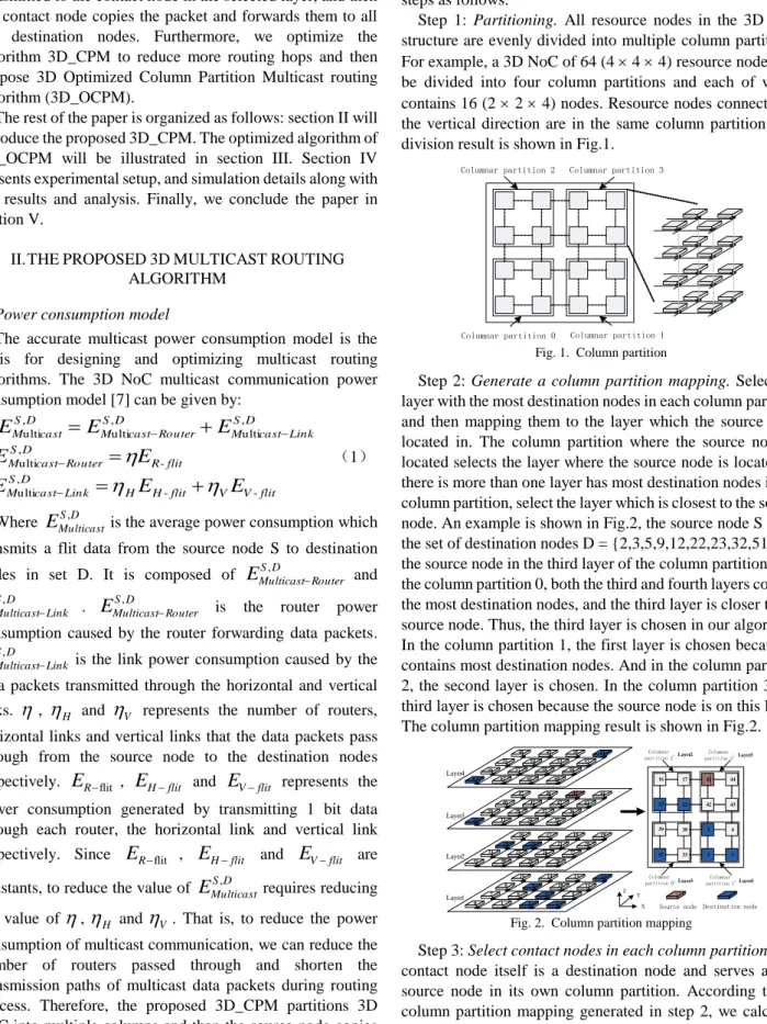
Step 1: Partitioning. All resource nodes in the 3D NoC structure are evenly divided into multiple column partitions.
For example, a 3D NoC of 64 (4 4 4) resource nodes can be divided into four column partitions and each of which contains 16 (2 2 4) nodes. Resource nodes connected in the vertical direction are in the same column partition. The division result is shown in Fig.1.
Columnar partition 2 Columnar partition 3
Columnar partition 0 Columnar partition 1
Fig. 1. Column partition
Step 2: Generate a column partition mapping. Select the layer with the most destination nodes in each column partition, and then mapping them to the layer which the source node located in. The column partition where the source node is located selects the layer where the source node is located. If there is more than one layer has most destination nodes in the column partition, select the layer which is closest to the source node. An example is shown in Fig.2, the source node S = 45, the set of destination nodes D = {2,3,5,9,12,22,23,32,51,63}, the source node in the third layer of the column partition 3. In the column partition 0, both the third and fourth layers contain the most destination nodes, and the third layer is closer to the source node. Thus, the third layer is chosen in our algorithm.
In the column partition 1, the first layer is chosen because it contains most destination nodes. And in the column partition 2, the second layer is chosen. In the column partition 3, the third layer is chosen because the source node is on this layer.
The column partition mapping result is shown in Fig.2.
32 33 2 3
23 22 42 43
16 17 45 44
39 38 5 4
Columnar partition 2
Columnar partition 0
Source node Destination node
:Layer3
:Layer2 Columnar partition 3:Layer3
Columnar partition 1:Layer1
X Y Z
31 30 29 28
24 25 26 27
23 22 21 20
16 17 18 19
0 1 2 3
15 14 13 12
8 9 10 11
7 6 5 4
32 33 34 35
39 38 37 36
40 41 42 43
47 46 45 44
63 62 61 60
56 57 58 59
55 54 53 52
48 49 50 51
Layer4
Layer2
Layer1 Layer3
Fig. 2. Column partition mapping
Step 3: Select contact nodes in each column partition. The
contact node itself is a destination node and serves as the
source node in its own column partition. According to the
column partition mapping generated in step 2, we calculate
the horizontal Manhattan distances [8] from the source node
to all destination nodes in the mapping layer (except the
partition of source node) respectively. In each column
partition, we choose one destination node as the contact node
which has shortest horizontal Manhattan distance to the
source node. According to the example shown in Fig.2, we
select the node 32, 5 and 22 as the contact node of column
partition 0, 1 and 2 respectively. The result is shown in Fig.3.
Source node
Destination node Contact node
X Z Y
Columnar partition 0
0 1
6 7
31 30
24 25
32 33
38 39
63 62
56 57
Columnar partition 1
2 3
5 4
29 28
27 26
34 35
36 37
61 60
58 59
Columnar partition 2
8 8
14 15
23 22
17 16
40 41
47 46
55 54
49 48
Columnar partition 3
10 11
12 13
21 20
19 18
42 43
45 44
53 52
51 50
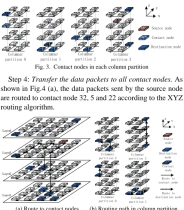
Fig. 3. Contact nodes in each column partition
Step 4: Transfer the data packets to all contact nodes. As shown in Fig.4 (a), the data packets sent by the source node are routed to contact node 32, 5 and 22 according to the XYZ routing algorithm.
Source node
Destination node Contact
node Route to contact node Columnar
partition 2 Columnar partition 3
Columnar
partition 0 Columnar partition 1
Route to destination node
31 30 29 28
24 25 26 27
23 22 21 20
16 17 18 19
0 1 2 3
15 14 13 12
8 9 10 11
7 6 5 4
32 33 34 35
39 38 37 36
40 41 42 43
47 46 45 44
63 62 61 60
56 57 58 59
55 54 53 52
48 49 50 51
Layer4
Layer2
Layer1 Layer3
8 8
14 15
23 22
17 16
40 41
46 47
55 54
48 49
10 11
13 12
21 20
19 18
42 43
44 45
53 52
51 50
0 1
7 6
31 30
25 24
32 33
38 39
63 62
57 56
2 3
4 5
29 28
27 26
34 35
36 37
61 60
58 59
X Y Z
(a) Route to contact nodes (b) Routing path in column partition Fig. 4. Two-step routing paths of 3D_CPM
Step 5: Transfer data packets to all destination nodes. The contact node in each column partition acts as the source node in its own column partition. It copies the data packet and uses XYZ routing algorithm to forward them to destination nodes in the column partition which it is located in. As shown in Fig.4 (b), the contact node 32 copies the packet and forwards it to the destination node 63 in the column partition 0. In column partition 1, the contact node 5 copies the packets and forwards them to destination nodes 2 and 3 respectively. In column partition 2, the contact node 22 copies the data packets and forwards them to destination nodes 9 and 23 respectively. In column partition 3, the source node sends the data packet to node 44. Then node 44 copies the packets and forwards them to destination nodes 12 and 51.
As the example shown in Fig.2, multicast routing paths generated by the 3D_CPM is shown in Fig.5. Firstly, the source node sends data packets to the contact nodes in each column partition with the XYZ routing algorithm. Secondly, each contact node sends the data packet to all the destination nodes of its partition according to the XYZ routing algorithm.
This algorithm can effectively reduce the number of routing hops in the vertical direction.
31 30 29 28
24 25 26 27
23 22 21 20
16 17 18 19
0 1 2 3
15 14 13 12
8 9 10 11
7 6 5 4
32 33 34 35
39 38 37 36
40 41 42 43
47 46 45 44
63 62 61 60
56 57 58 59
55 54 53 52
48 49 50 51
Layer4
Layer2
Layer1 Layer3
Source node
Destination node
Contact node
Route to contact node
Route to destination node
X Y Z
Fig. 5. Multicast routing paths of 3D_CPM
III. THE OPTIMIZED MULTICAST ROUTING ALGORITHM 3D_OCPM
In the 3D_CPM routing algorithm, the main consideration is to reduce the number of links in the vertical direction. The fourth step and the fifth step all use XYZ routing algorithm, which can not make full use of the horizontal common transmission paths. Therefore, we optimize 3D_CPM and then propose 3D Optimized Column Partition Multicast routing algorithm (3D_OCPM). The same as 3D_CPM, 3D_OCPM routing algorithm is also divided into five steps.
However, in order to reduce the number of hops in the horizontal direction, the power consumption of the six routing algorithms (XYZ, XZY, YXZ, YZX, ZXY and ZYX) is calculated separately. Then the routing algorithm with minimal link power consumption is selected to calculate the direction of the next routing hop, instead of using the XYZ routing algorithm by default in 3D_CPM. Each time a packet is routed to a node, it needs to perform this step in order to minimize the hops of transmission paths.
Link power consumption is an important part of the multicast communication power consumption. Reducing link power consumption can improve the performance of system.
According to the communication power consumption model of multicast routing algorithm, the link power consumption is related to the number of horizontal and vertical hops transmitted through by data packets. Since TSV transfers 1 bit of data only consumes 7.5% [5] of the power consumed by horizontal link, link power consumption of routing algorithm can be calculated by:
Cost
H
V 7 . 5 %
(2) Where
Hand
Vrespectively represents the number of horizontal and vertical hops that the data packets pass from the source node to the destination nodes. The number of horizontal hops has a great influence on the link power consumption. Therefore, reducing
Hcan effectively reduce the link power consumption.
As the example shown in Fig.2, the routing paths of six routing algorithms are shown in Fig.6.
31 30 29 28
24 25 26 27
23 22 21 20
16 17 18 19
0 1 2 3
15 14 13 12
8 9 10 11
7 6 5 4
32 33 34 35
39 38 37 36
40 41 42 43
47 46 45 44
Layer2
Layer1 Layer3
31 30 29 28
24 25 26 27
23 22 21 20
16 17 18 19
0 1 2 3
15 14 13 12
8 9 10 11
7 6 5 4
32 33 34 35
39 38 37 36
40 41 42 43
47 46 45 44
Layer2
Layer1 Layer3
Source node
Destination node
Contact node
Route to contact node
X Y Z
(a)XYZ (b) XZY
Source node
Destination node
Contact node
Route to contact node
X Y Z
31 30 29 28
24 25 26 27
23 22 21 20
16 17 18 19
0 1 2 3
15 14 13 12
8 9 10 11
7 6 5 4
32 33 34 35
39 38 37 36
40 41 42 43
47 46 45 44
Layer2
Layer1 Layer3
31 30 29 28
24 25 26 27
23 22 21 20
16 17 18 19
0 1 2 3
15 14 13 12
8 9 10 11
7 6 5 4
32 33 34 35
39 38 37 36
40 41 42 43
47 46 45 44
Layer2
Layer1 Layer3
(c) YXZ (d) YZX
Source node
Destination node
Contact node
Route to contact node
X Y Z
31 30 29 28
24 25 26 27
23 22 21 20
16 17 18 19
0 1 2 3
15 14 13 12
8 9 10 11
7 6 5 4
32 33 34 35
39 38 37 36
40 41 42 43
47 46 45 44
Layer2
Layer1 Layer3
31 30 29 28
24 25 26 27
23 22 21 20
16 17 18 19
0 1 2 3
15 14 13 12
8 9 10 11
7 6 5 4
32 33 34 35
39 38 37 36
40 41 42 43
47 46 45 44
Layer2
Layer1 Layer3
(e) ZXY (f) ZYX
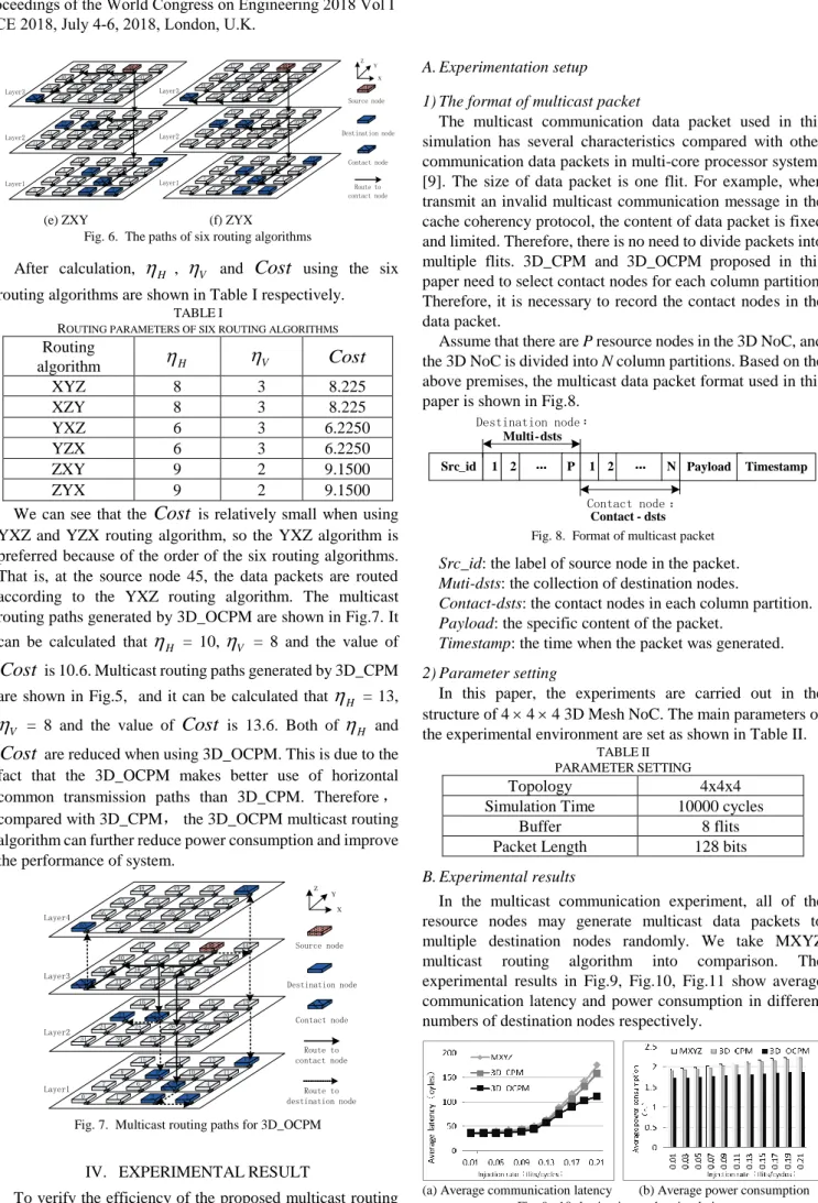
Fig. 6. The paths of six routing algorithms
After calculation,
H,
Vand Cost using the six routing algorithms are shown in Table I respectively.
TABLE I
R
OUTING PARAMETERS OF SIX ROUTING ALGORITHMSRouting
algorithm
H
VCost
XYZ 8 3 8.225
XZY 8 3 8.225
YXZ 6 3 6.2250
YZX 6 3 6.2250
ZXY 9 2 9.1500
ZYX 9 2 9.1500
We can see that the Cost is relatively small when using YXZ and YZX routing algorithm, so the YXZ algorithm is preferred because of the order of the six routing algorithms.
That is, at the source node 45, the data packets are routed according to the YXZ routing algorithm. The multicast routing paths generated by 3D_OCPM are shown in Fig.7. It can be calculated that
H= 10,
V= 8 and the value of
Cost is 10.6. Multicast routing paths generated by 3D_CPM are shown in Fig.5, and it can be calculated that
H= 13,
V= 8 and the value of Cost is 13.6. Both of
Hand
Cost are reduced when using 3D_OCPM. This is due to the fact that the 3D_OCPM makes better use of horizontal common transmission paths than 3D_CPM. Therefore , compared with 3D_CPM, the 3D_OCPM multicast routing algorithm can further reduce power consumption and improve the performance of system.
Source node
Destination node
Contact node
Route to contact node
Route to destination node
X Y Z
31 30 29 28
24 25 26 27
23 22 21 20
16 17 18 19
0 1 2 3
15 14 13 12
8 9 10 11
7 6 5 4
32 33 34 35
39 38 37 36
40 41 42 43
47 46 45 44
63 62 61 60
56 57 58 59
55 54 53 52
48 49 50 51
Layer4
Layer2
Layer1 Layer3
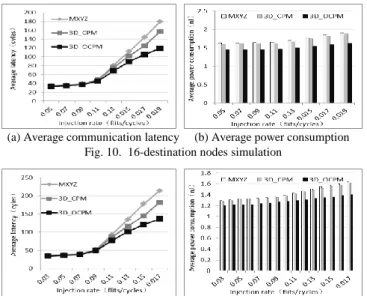
Fig. 7. Multicast routing paths for 3D_OCPM
IV. EXPERIMENTAL RESULT
To verify the efficiency of the proposed multicast routing algorithms 3D_CPM and 3D_OCPM, we modify the Noxim to supports the simulation of multicast routing algorithms [10].
A. Experimentation setup 1) The format of multicast packet
The multicast communication data packet used in this simulation has several characteristics compared with other communication data packets in multi-core processor systems [9]. The size of data packet is one flit. For example, when transmit an invalid multicast communication message in the cache coherency protocol, the content of data packet is fixed and limited. Therefore, there is no need to divide packets into multiple flits. 3D_CPM and 3D_OCPM proposed in this paper need to select contact nodes for each column partition.
Therefore, it is necessary to record the contact nodes in the data packet.
Assume that there are P resource nodes in the 3D NoC, and the 3D NoC is divided into N column partitions. Based on the above premises, the multicast data packet format used in this paper is shown in Fig.8.
1 2
...
PSrc_id 1 2 N Payload Timestamp
Destination node : Multi- dsts
Contact node :
...
Contact - dsts
Fig. 8. Format of multicast packet Src_id: the label of source node in the packet.
Muti-dsts: the collection of destination nodes.
Contact-dsts: the contact nodes in each column partition.
Payload: the specific content of the packet.
Timestamp: the time when the packet was generated.
2) Parameter setting
In this paper, the experiments are carried out in the structure of 4 4 4 3D Mesh NoC. The main parameters of the experimental environment are set as shown in Table II.
TABLE II PARAMETER SETTING
Topology 4x4x4
Simulation Time 10000 cycles
Buffer 8 flits
Packet Length 128 bits
B. Experimental results
In the multicast communication experiment, all of the resource nodes may generate multicast data packets to multiple destination nodes randomly. We take MXYZ multicast routing algorithm into comparison. The experimental results in Fig.9, Fig.10, Fig.11 show average communication latency and power consumption in different numbers of destination nodes respectively.
(a) Average communication latency (b) Average power consumption
Fig. 9. 10-destination nodes simulation
(a) Average communication latency (b) Average power consumption Fig. 10. 16-destination nodes simulation
(a) Average communication latency (b) Average power consumption Fig. 11. 26-destination nodes simulation
In Fig.9 (a), Fig.10 (a) and Fig.11 (a), we can see that when the injection rate is less than 0.13, the average communication latency is almost the same. When the injection rate increases gradually, the average communication latency of 3D_CPM and 3D_OCPM is obviously smaller than MXYZ, and the latency of 3D_OCPM is smallest. This is because compared with MXYZ routing algorithm, 3D_CPM multicast routing algorithm mainly reduces vertical routing hops, and the average communication latency decreases slightly. Based on the 3D_CPM, the optimized 3D_OCPM reduces more horizontal routing hops and average communication latency than MXYZ. In Fig.9 (b), Fig.10 (b) and Fig.11 (b), the average communication power consumption of 3D_CPM and 3D_OCPM are smaller than MXYZ in the different numbers of destination nodes. Since the power consumption on the vertical link has little effect on the total power consumption, the average power consumption of 3D_CPM decreases slightly compared with MXYZ. The power consumption on the horizontal link has a greater impact on the total power consumption, so the average power consumption of the 3D_OCPM is significantly lower than that of the other two multicast routing algorithms. The percentages for the optimized average communication latency and average communication power consumption are shown in Table III and Table Ⅳ respectively.
TABLE IV
AVERAGE LATENCY OPTIMIZATION RESULTS Algorithm
Number
Compared with MXYZ
3D_CPM 3D_OCPM
10 5.52 15.76
16 6.33 16.45
26 6.81 16.01
TABLE V
AVERAGE POWER CONSUMPTION OPTIMIZATION RESULTS Algorithm
Number
Compared with MXYZ
3D_CPM 3D_OCPM
10 2.15 14.32
16 2.17 15.26
26 2.31 14.84
Through the analysis of above three groups experiments,
we can see that when use the 3D_CPM and 3D_OCPM to route packets with different numbers of destination nodes, the system performance are both improved. In the three groups of experiments, the performance of 3D_OCPM improves the most when the number of destination nodes is 16. Compared with MXYZ, 3D_OCPM can reduce the average latency by 16.45% and save power consumption by 15.26%, and 3D_CPM can reduce the average latency by 6.33% and save power consumption by 2.17%. Since 3D_CPM mainly reduces the hops in the vertical direction compared with MXYZ, its performance is slightly improved. And 3D_OCPM makes full use of common transmission paths, the performance of 3D_OCPM is improved significantly.
V. C ONCLUSION
In this paper, we propose a multicast routing algorithm 3D_CPM for 3D NoC in order to realize the multicast communication in 3D NoC based CMP. 3D_CPM firstly divides the 3D NoC into several column partitions, and then select the appropriate contact node in different column partitions. 3D_CPM transmit data packets to contact nodes from source node through XYZ routing algorithm, and finally transmit to destination nodes. Furthmore, we optimize the algorithm 3D_CPM to reduce more routing hops, and propose 3D_OCPM. This algorithm selects the shortest transmission paths between nodes, which makes full use of the common transmission paths and reduces power consumption. The experimental results show that, the proposed 3D_CPM and 3D_OCPM multicast routing algorithms can improve the performance of system effectively.
R EFERENCES
[1] Wang L, Jin Y, Kim H, et al. Recursive partitioning multicast: A bandwidth-efficient routing for Networks-on-Chip[C]. ACM/IEEE International Symposium on Networks-On-Chip. IEEE Computer Society, 2009:64-73.
[2] Ma S, Wang Z, Jerger N E, et al. Novel Flow Control for Fully Adaptive Routing in Cache-Coherent NoCs[J]. IEEE Transactions on Parallel & Distributed Systems, 2014, 25(9):2397-2407.
[3] Kumar D R, Najjar W A, Srimani P K. A New Adaptive Hardware Tree-Based Multicast Routing in K-Ary N-Cubes[J]. Computers IEEE Transactions on, 2001, 50(7):647-659.
[4] Abad P, Puente V, Gregorio J. MRR: Enabling fully adaptive multicast routing for CMP interconnection networks[C]. IEEE, International Symposium on High PERFORMANCE Computer Architecture, 2009:355-366.
[5] Wang X, Palesi M, Yang M, et al. Low latency and energy efficient multicasting schemes for 3D NoC-based SoCs[C]. IEEE/IFIP, International Conference on Vlsi and System-On-Chip. IEEE, 2011:337-342.
[6] Wang P, Ma S, Lu H, et al. A comprehensive comparison between virtual cut-through and wormhole routers for cache coherent Network on-Chips[J]. IEICE Electron Express, 2014, 11(14):20140496- 20140496.
[7] Jerger, Natalie Enright, Peh, LiShiuan, Lipasti, Mikko. Virtual Circuit Tree Multicasting: A Case for On-Chip Hardware Multicast Support[J].
Acm Sigarch Computer Architecture News, 2008, 36(3):229-240.
[8] Kim D H, Mukhopadhyay S, Lim S K. Through-silicon-via aware interconnect prediction and optimization for 3D stacked ICs[C]. The, International Workshop on System-Level Interconnect Prediction.
DBLP, 2009:85-92.
[9] Wang L L, Zhang D K, Song G Z. Study of Routing Algorithms for Three Dimensional Networks-on-chip[J]. Journal of Chinese Computer Systems, 2014, 35(8):1816-1821.
[10] Xie M. Design of three-dimensional network-on-chip simulator based
on SystemC[J]. Electronic Measurement Technology,
2012,35(6):98−101.