XZEED
DLP
A multi-material 3D printer using DLP® technologyFinal bachelor assignment industrial design 10 July 2015, Enschede
XZEED DLP 3
Design and construction of a multi-material 3D DLP printer.
Examination board:
- Chairman: Theo van der Meer - UT tutor: Tom Vaneker
The examination will take place on 15 July 2015
University of Twente Industrial design
Final Bachelor Assignment 10 July 2015,
Number of pages: 91 Number of appendices: 13
Foreword 5
Foreword
The reason for development of a multi-material DLP 3D printer is to proof the principle of multi-material printing using DLP technology. Many designers could benefit from the possibility of this technology since DLP printing is considered to be fast and more accurate than other 3D printing techniques and also has the possibility to achieve very high resolutions with smooth finished surfaces. Enabling material switching during printing might enable building new products, which can have electric conductive paths, or regionally adjustable stiffness, for example. For me this project was a bit different than the other projects in my bachelor since a full functional prototype had to be built from scratch. Since the mechanical demands in terms of accuracy, precision, and optic specifications were a lot higher than for the other projects, much investigation had to be done on how to get the materials, tools and how to calibrate the prototype. For building the prototype I required many parts, about which I didn’t have knowledge in advance. The time for the project was very short and often concerned me. This resulted in long days of hard working. Designing and building the prototype really demanded a lot of me. Also the insecure feeling of
dependency on other people kept me busy. For this project this resulted in unplanned slowdown. Later if I would work in the industry this would also happen, but then this would also cost money. I have applied lot things of what I’ve learned during my bachelor. From materials to construction using laser cutting, 3D printing, drilling and using a lathe, from generating concepts to modelling in Solidworks, from selecting electronics and
programming and communication. It was a hard assignment. Looking at the result I’m very proud of what I’ve achieved in the limited time of only three months. Every part fits very neatly as I have designed and the printer looks very professional. It’s a pity that I didn’t have time to validate the possibility of printing objects, although I’m pretty sure that it will work as soon as it’s calibrated. Now I’m looking back on the result with a very satisfied feeling.
Table of Contents
XZEEDDLP ... 1
Foreword ... 5
Table of Contents ... 6
Abstract ... 8
Abstract (Dutch) ... 10
Introduction ... 12
Advantages ... 12
Disadvantages ... 12
Method ... 13
DLP technology ... 14
Digital Light Processing ... 14
DLP Beamers ... 14
DLP technology for 3D printing ... 16
Photopolymer resin... 16
Monomer & oligomers ... 18
Photo initiator ... 18
Blockers ... 19
Photosensitizers ... 20
Inhibition by oxygen (only for free radical reactions) ... 20
Extra ingredients ... 21
Shrink ... 21
Dose & layer thickness ... 21
Wavelength... 21
XY and Z resolution ... 22
Mechanical resolution Z-axis ... 22
Bottom-up or top-down printing ... 22
Conclusions about the analysis ... 25
Reference DLP Printers ... 26
Envisiontec Perfectory ... 26
Tristram Budel’s 3D SLA printer Instructable ... 27
B9Creator ... 28
DLP printer with active tilt system made by ‘watsonstudios’ ... 30
Carbon3D continuous printing using CLIP technology ... 30
LittleRP ... 31
Conclusion about the existing printers ... 32
Table of Contents 7
Linear printer ... 35
Simplicity ... 35
Compatibility ... 35
Ideas worth mentioning ... 36
Conclusions about
theidea phase ... 36
The EXZEED printer ... 37
Moving vat carrier ... 37
Vats ... 37
Stepper motor control ... 38
Spindles ... 39
Arduino & motherboard ... 39
Firmware ... 41
Vats ... 43
The body ... 47
Hood ... 48
Making the parts ... 48
Assembling ... 48
Conclusion ... 49
Recommendations ... 53
Problems ... 53
Opportunities ... 53
Future research ... 53
Bibliography ... 55
Appendix 1: Properties of monomer & oligomers... 59
Appendix 2: Properties of Photo initiators ... 61
Appendix 3: Stepper motor and driver carrier datasheet ... 64
Appendix 4: Stepper motor properties ... 65
Appendix 5: Spindle choice ... 66
Appendix 6: Explanation of the throw modification of the beamer. ... 67
Appendix 7: Bill of materials ... 68
Appendix 8: The laser cut parts ... 73
Appendix 9: 3D printed parts ... 77
Appendix 10: The aluminium parts ... 80
Appendix 11: Assembling the parts ... 81
Gluing the hood ... 83
Assembling the mirror ... 85
Connecting the wires ... 85
Appendix 12: Firmware configuration ... 88
Abstract
The 3D DLP printing process was studied. In DLP printing a projection coming from a DLP beamer is projected on a resin containing photo
initiators, monomer and blockers. A thin layer in the shape of the projection is polymerised and a moveable build platform moves this layer one-layer thickness so that a new layer can be polymerised. Since photo initiators are sensitive to specific wavelengths of light mostly in the UV-A (λ<400nm) and near UV band (400-420nm), the optical system has to be designed for curing within these bands. There are many aspects that influence the
polymerization process: The formula of the resin, inhibition by oxygen, the wavelength band of the projected light, the intensity, the exposure time, and temperature. They result in the amount of shrink, the density, toughness, the amount of uncured resin, the thickness of the curing gradient and the optimal layer thickness. The resolution of the beamer and the projected size account for the XY accuracy of a printed object, although shrink and bleed cause inaccuracy. The minimal step resolution of the motor driving the Z-axis is called the mechanical resolution. This is the linear movement per step. The resolution in the Z-axis is also influenced by how accurate the focus is. Since the refraction index of a lens system is wavelength-dependent, the focus will differ for lower and higher wavelengths, thus the more monochromatic the light, the lower the range of focus points, thus the higher the Z-accuracy. Projecting monochromatic light at the photo initiator’s peak-absorbance wavelength is also better, since less light energy will be transferred to heat because of absorbance by pigments and blockers. The higher the
temperature, the higher to polymerization rate and the higher the amount of shrink.
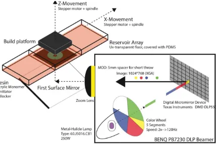
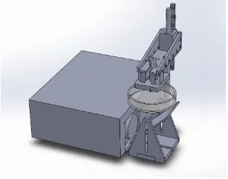
Abstract 9 Inspired by the existing printers and by taking care of the theory, a multi material 3D DLP printer prototype was designed (Fig.1) and build. This printer features a moving array of petri dishes covered with a layer of PDMS and a passive tilting system (1) to make the layer peeling easy. A modified DLP beamer (2) was used as the source of the projection and projects via a mirror (3) to the bottom of the petri dishes. A build platform (4) pulls the object out of the vat. The control of the stepper motors (5) was done by a motherboard (6) loaded with firmware that communicates with host
software. This host software controls the beamer concurrently to the motors. The printer was mainly build using 3D printing and laser cutting, although some post processing of the parts was needed to bring up the result.
Figure 1:The result with removed front planes
1
2 6
3 4
5
Abstract (Dutch)
Het 3D DLP print proces is bestudeerd. Bij DLP printing wordt een afbeelding op een oplossing met foto initiators, monomeren en blockers geprojecteerd. Een dunne laag vloeistof wordt in de vorm van de projectie gepolymeriseerd. Vervolgens verplaatst een bouwplatform zich met 1 laagdikte zodat een volgende laag gepolymeriseerd kan worden. Omdat foto initiatoren gevoelig voor specifieke golflengtes, meestal in de UV-A
(λ<400nm) en bijna-UV(400-420nm) banden, moet het optische system ervoor geschikt zijn om de vloeistof te kunnen uitharden in deze banden. Er zijn veel aspecten die het polymerisatie proces beïnvloeden: De
samenstelling van de oplossing, de tegenwerking van zuurstof, de
bandbreedte van het geprojecteerde licht, de intensiteit en belichtingstijd en de temperatuur van de oplossing. Deze variabelen hebben uitwerking op de hoeveelheid krimp, de dichtheid, de stugheid, de hoeveelheid niet uitgeharde oplossing, de dikte van de uithard gradiënt en de optimale laagdikte. De resolutie van de beamer en het geprojecteerde oppervlakte zijn
verantwoordelijk voor de XY nauwkeurigheid van een geprint object, hoewel krimp en vloeiing dit negatief beïnvloeden. De lineaire verplaatsing die één motorstap veroorzaak is de mechanische resolutie van de Z-as. De resolutie van het te printen object wordt ook beïnvloed door de accuraatheid van de focus. Omdat breking van een lenzensysteem golflengte-afhankelijk is, zal de focus verschillen voor lage en hogere golflengtes. Hoe beter het licht
monochromatisch is, hoe lager het bereik van de focuspunten is, dus hoe hoger de Z-nauwkeurigheid. Het projecteren van monochromatisch licht in de piek-golflengte van de initiator is ook beter, omdat de door het pigment geblokkeerde licht energie wordt omgezet in warmte. Hoe hoger de temperatuur, hoe groter de polymerisatie snelheid en hoe groter de krimp.
Een aantal bestaande 3D printers zijn geanalyseerd. Eén van de belangrijkste aspecten bij het bouwen van een DLP printer, is een anti-plak oplossing. Omdat de projectie van onderaf, de onderste laag moleculen in het vat doet polymeriseren, zullen deze gaan plakken aan het vat door adhesie krachten. Ook de luchtdruk zorgt voor het plakken, want het optillen van het platform veroorzaakt een vacuüm dat aan het product ‘trekt’. Hiervoor zijn
Abstract (Dutch) 11 reduceren de kracht significant. Het controleren van de
tegenwerkingssnelheid van zuurstof maakt deze stappen overbodig. (CLIP technologie.
Geïnspireerd op de bestaande printers en rekening houdend met de theorie, is er een prototype ontworpen en gebouwd. Deze printer heeft een
bewegende houder voor petrischalen die bedekt zijn met een laagje PDMS en voorzien is van een passief kantel systeem(1) om het pellen makkelijk te maken. Een gemodificeerde beamer werd gebruikt als bron voor de projectie en projecteert via een spiegel(3) op de bodem van een vat. Het regelen van de stapmotoren(5) wordt gedaan door een moederbord voorzien van firmware die communiceert met de host software. Deze host software stuurt de beamer aan gelijktijdig met do motoren. De printer is hoofdzakelijk gebouwd door gebruik te maken van 3D printing en laser snijden. Hoewel veel handmatige nabewerking van de onderdelen nodig was om het resultaat te vervaardigen.
Figure 2: Het resultaat met de voorpanelen verwijderd. 1
2 6
3 4
5
Introduction
3D printing is a strong developing technology which is considered to be a very important method for making products in the future. It has certain advantages to conventional production techniques en makes it possible to
make product that couldn’t be built in other ways. (Hopkinson, Haque, &
Dickens, 2005) 3D Printing can be done using various methods which each has their own advantages and disadvantages. A promising method is 3D DLP printing. This is one of the vat polymerisation SLA techniques. It works by projecting images to a resin in layers, partly masked. This technology uses a light source that projects light on a Digital Micro mirror Device, which reflects the light with millions of microscopic mirrors that together form an image. On the spot where the image projects, a photo polymerisation process is initialised and thus cures. By moving a build platform, a new layer can be cured and a 3D product appears. Big advantages are the possibility to cure fast and with high accuracy, with a clean appearing surface finish. One of the disadvantages is that they are limited to a single material. This is why it is not possible to print a product that has soluble support material.
Advantages
The biggest advantage related to other techniques is that a whole layer is cured at once. This reduces the positioning errors in the XY-plane due limited mechanical movement. The mechanical system is less complex then other techniques, since it only consist of a single axis of movement. The resolution of 3D printed parts using DLP printing is considered to be very high and the surface finish is smooth. This makes DLP printing suitable for the production of masters for injection moulding. Since in DLP printing the minimal diameter of vertical oriented objects is smaller, the supports can be a lot thinner then in FDM.
Disadvantages
Method 13
Method
The goal of this project is to develop a prototype for a DLP printer capable of printing multiple materials. In order to do this, the printer has 5 moveable vats. Before the design of the printer could start, research to the principle had to be done in order to be able to make the right design choices. The following aspects of interest:
(A) Photo polymerisation (B) The influence of light (C) Layer thickness (D) XY-Accuracy (E) Z-accuracy
The design of the printer was done in the following way:
(A) Analysis of existing printer, estimating the boundary conditions for the design
(B) Determination of available components, existing software and compatibility.
(C) Design of the electronics and functional components (Connections, interfaces, motor control etc.)
(D) Tuning software to own system (E) Building a physical prototype
A manual on how to design a normal DLP printer made from a beamer
already existed. (Budel, 2013) Stepper motors, a beamer (Benq PB7230) and
a 20mm lead spindle were already available. Other parts were bought from vendors. Software is available, although needs to be extended in
DLP technology
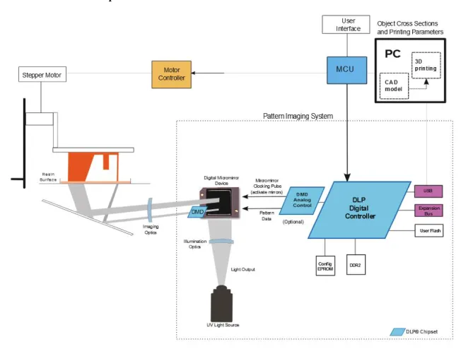
Digital Light Processing
DLP stands for Digital Light Processing. This technology is developed by Texas Instruments for multiple applications, including projectors, spectroscopy, 3D scanners, machine vision, head-up displays and medical applications, (Texas Instruments, 2015) The technology is basically a matrix of millions of microscopic mirrors which have an angle that can be controlled from a Digital Micro mirror Device (DMD) controller (1220 in Fig. 3), which has digital input from a microcontroller. (1240)
DLP Beamers
In a DLP beamer the light passes from a lamp (1210) through a spinning colour wheel (1230), on the DMD chip. From the DMD chip (1220) the light is projected through a lens system (1250) onto the screen (1270)
Figure 3: DLP Beamer Technology by Texas Instruments (Anthony DiCarlo, 2015)
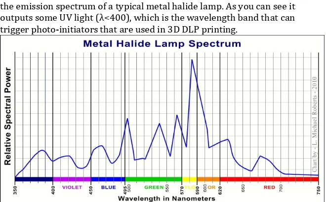
Metal halide lamp
DLP technology 15 ionizes and produces photons. They consist of a small fused quartz glass tube surrounded by a glass bulb with a coating to filter most of the UV, although some of it passes. (Wikipedia: Metal-halide lamp, 2015) Below is an image of the emission spectrum of a typical metal halide lamp. As you can see it outputs some UV light (λ<400), which is the wavelength band that can trigger photo-initiators that are used in 3D DLP printing.
Figure 4: Spectrum of a typical metal halide lamp (Wikipedia: Metal-halide lamp, 2015)
Colour wheel
After the light has left the lamp, it passes through a colour wheel. This is a
small spinning wheel, which spins at 𝐶𝑜𝑙𝑜𝑢𝑟 𝑊ℎ𝑒𝑒𝑙 𝑆𝑝𝑒𝑒𝑑 ∙ 60𝐻𝑧. In the
Benq beamer it spins at 120Hz. The colour wheel filters the white light in chunks of light with specific colours by absorbing the others. The DMD chip is programmed to be timed according the position of the colour wheel. When for example a red screen has to be projected, the DMD only mirrors the light at the moments when the chunk of light that passes though the Colour Wheel is red. The colour wheel blocks certain wavelengths, however even without removing the colour wheel, there is still UV-output.
Digital Micro mirror Device
The DMD technology is owned by Texas Instruments. It is invented by dr. Larry Hornbeck in 1987. (Texas Instruments, 2015) Nowadays it consists of a thumbnail sized chip with millions of controllable mirrors. 2560x1600 is the maximum available resolution at the moment. (Texas Instruments, 2015) Typical chips used in standard beamers are the DLP5500 0.55 XGA DMD and the DLP7000 .7 XGA 2xLVDS Type-A DMD. These Chips use the XGA
resolution (1024x768) Besides the resolution, another important parameter for the purpose of 3D printing is the reflection wavelength range. For the .70 this is 400-700 and for the .55 this is 420-700 (which is the DMD used in the Benq beamer that was available for this project). Texas Instruments
DLP6500FYE, DLP6500FLQ, DLP9000, The DMD’s with “UV” in it reflect 363-420nm (Texas Instruments, 2015) so the mirror reflect more light in the curing wavelength band and works as a filter to output just the right wavelengths at once.
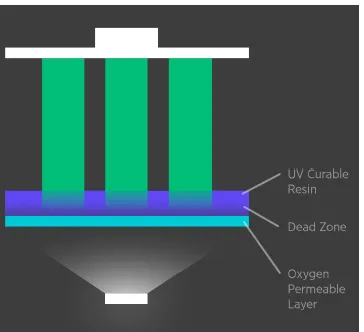
DLP technology for 3D printing
[image:16.499.86.412.231.478.2]DLP technology can be used for 3D printing. A thin layer of resin is cured by projecting an image on a photopolymer resin. After a thin layer is cured, a stepper motor moves the layer one layer thickness upward or downward (see the bottom-up & top-down section) A new image is projected and this continuous until a 3D product is made. In (Fig. 5) an overview made by Texas Instruments. Is depicted.
Figure 5: DLP technology for 3D printing (Texas Instruments, 2015)
Photopolymer resin
The photopolymer resin might be one of the most important parameters for accuracy and precision in DLP printing. Although the range of resins commercially available is big, they are all based on the same combination of ingredients: They consist of monomers/oligomers, a photo initiator
DLP technology 17 through epoxy groups and free radical is polymerization through double bonds in for example (Meth)Acrylate.
Cationic curing (epoxides, oxetanes and vinyl ethers etc.) (Crivello & Reichmanis, 2013)
When in cationic curing a photo initiator is exposed to light with the right amount of energy it releases a Lewis acid. These acids react with epoxy groups and this results in polymerization.
Figure 6: Cationic photo polymerization mechanism (Wikipedia: Photopolymer, 2015)
Free radical curing (acrylates, styrenes etc.)
When the initiator is exposed to a photon with the right amount of energy, it generates a free radical (initiation) and immediately seeks a double bond of a monomer/oligomer to attach to. The reaction continues by attaching to other monomers. (Propagation) The reaction stops if the end of the chain is connected to another chain. There are two possibilities: They together form one big chain (combination) or one of the chains transmits a hydrogen atom to the other resulting in two shorter polymer chains. (Disproportionation)
Figure 7: Free radical photo polymerization mechanism (Wikipedia: Photopolymer, 2015)
Resin formula
the lower the molecular weight and the lower the crosslink density. An example of a resin composition is the following recipe: (Bucktownpolymers, 2013)
Monomer: 1000 ml 1,6-Hexanediol diacrylate (also known as HDODA) Photo initiator: 20 g Phenylbis(2,4,6-trimethylbenzoyl)phosphine oxide (known as Irgacure 819)
Blocker: 0,06 g 1-phenylazonaphth-2-ol (known as Sudan I)
Monomer & oligomers
For 3D printing many monomers/oligomers can be used but they all have their own specifications regarding curing speed and viscosity. Acrylates cure fast so these will be useful. There is a table in Appendix 1 that describes curing properties for various acrylic monomers. (3Dprinter.wikidot, 2011) Acrylic monomers can have different numbers (1,2 3, 4) of functional groups. Generally, but not always true: The more of higher functional group
monomer number is added, the lower the reaction speed, but the higher the viscosity reduction, the higher the flexibility, the higher the higher the adhesion and the higher the uncured residual. (Idacavage, 2012) This is caused by the decreased mobility of the monomers due the formation of a cross-linked network micro gel. (Lee, Sonny Jonson, Hoyle, & Guymon, 2004)
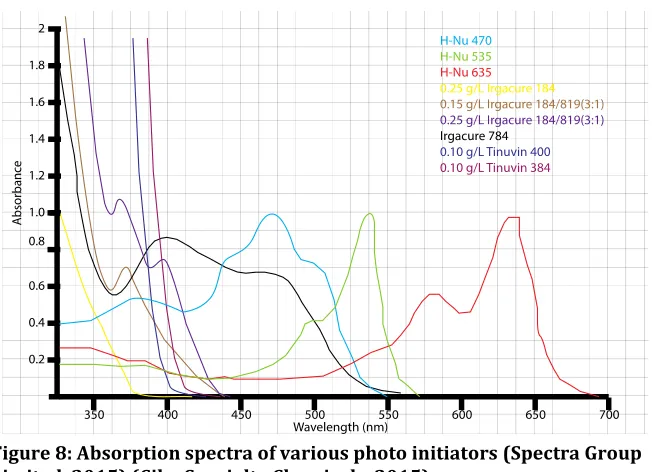
Photo initiator
DLP technology 19 Figure 8: Absorption spectra of various photo initiators (Spectra Group Limited, 2015) (Ciba Specialty Chemicals, 2015)
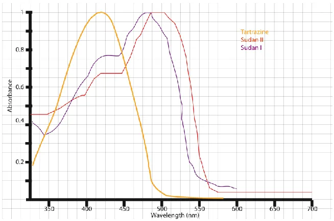
Blockers
Figure 9: Absorption Spectra of various blockers. (PerkinElmer, 2015) (Li, et al., 2007)
Photosensitizers
Sometimes photosensitizers are added, to extend the photosensitivity bandwidth of the initiators. They absorb light at wavelengths where the initiators are not sensitive to and transfer the excitation to the photo initiators. This way they extend the band that causes curing.
Inhibition by oxygen (only for free radical
reactions)
Oxygen can inhibit the photoreaction since it consumes free radicals. (Batch & Macosko, 1990). For (meth)acrylates, the oxygen concentration is
approximately 10-3 mol/L (Chong, 1969), which is higher, then the
concentration that allows polymerization. The influence of oxygen on the reaction depends on the chosen monomer. Trimethylol propane triacrylate is less sensitive to oxygen inhibition than 1,6-hexanediol diacrylate.
DLP technology 21
Extra ingredients
Other ingredients can be added to the formula, like metal or ceramic powder. After printing the metal can be burned-out and produces a cast-metal product. (Venus Creator, 2015)
Shrink
Since blocked light will be directly converted to heat and the polymerization reaction is exothermal, shrink will occur. The amount of shrink will depend on the monomer that was chosen. In Appendix 1 there are different shrink percentages noted down for different materials. The amount of shrink is between 5-10% for acrylics, but can be lowered if the amount of generated heat can be lowered, by just projecting the right wavelengths. For 1,6-hexanediol diacrylate the amount of shrink decreases when the temperature decreases and also decrease when the relative amount of photo initiator is decreased. The influence of the temperature is much stronger then the influence of the photo initiator concentration. (Ji, Chang, Ming, & Nie, 2013) For 3D printing purposes shrink is undesired so the temperature of the resin and the photo initiator concentration shouldn’t be too high.
Dose & layer thickness
Dose is a unit for the amount of effective light energy exposed to the resin. The curing rate increases when the rate of photons with the right
wavelengths is increased. The exposure time increases the amount of
photons exposed to the resin. 𝐷𝑜𝑠𝑒 = 𝑒𝑥𝑝𝑜𝑠𝑢𝑟𝑒 𝑡𝑖𝑚𝑒 ∗
𝑙𝑢𝑚𝑖𝑛𝑒𝑛𝑐𝑒@ 𝜆 𝑃ℎ𝑜𝑡𝑜𝑖𝑛𝑖𝑡𝑖𝑎𝑡𝑜𝑟 Layer thickness is dependent on the variable Dose, the amount of blocker, the monomer type and the amount of photo initiator. It is also dependent on the inhibition by oxygen. Dose can be regulated by the control of the beamer. The parameters are thus different for all resin
formulas.
Wavelength
The wavelength of the light projected on the resin should be about the same as that of the wavelength where the initiator is sensible to. All other wavelengths will not initiate the reaction and since the energy of these wavelengths is absorbed will result in heat. Heat is undesired since it causes the material to shrink, which limits the accuracy of the print. Another point of why only the right wavelengths should be projected is to limit dispersion: Since the refraction index of the material of the lens is dependent to
to block UV light. The different refraction indexes will result in unsharp prints.
XY and Z resolution
While using 3D printing, one of the main parameters for choosing the right printer is the maximum resolution. For DLP printing (like for many other printing techniques) the XY-resolution is different to the Z-resolution. The XY-resolution is determined by various influencers: The resolution of the DMD, lens distortions, the distance of the beamer to the bottom of the resin, scatter generated by blockers and shrink (see “Shrink”). The theoretical resolution when using a XGA beamer on a platform size with a width of
50mm, results in a XY-resolution of 1024 𝑝𝑖𝑥𝑒𝑙𝑠
50 𝑚𝑚 ≈ 20 𝑝𝑖𝑥𝑒𝑙𝑠/𝑚𝑚 or 1
20𝑑𝑜𝑡𝑠∗𝑚𝑚−1∗ 1000µ𝑚 = 50µ𝑚/𝑝𝑖𝑥𝑒𝑙. The Z-resolution is determined by the
mechanical resolution and is also influenced by shrink.
Mechanical resolution Z-axis
For DLP printers, manufacturers often speak about the mechanical
resolution. Since a stepper motor is used to drive the spindle where the build platform is attached to, the positions of that platform are discrete. This is because the motor has a minimum stepping angle. Activating micro stepping on the stepper driver lowers the stepping angle and thus the mechanical resolution. Another parameter is the chosen lead of the spindle. A smaller lead will result in a higher mechanical resolution, but will cut the maximum
speed down.𝑀𝑒𝑐ℎ𝑎𝑛𝑖𝑐𝑎𝑙 𝑟𝑒𝑠𝑜𝑙𝑢𝑡𝑖𝑜𝑛 = 𝑙𝑒𝑎𝑑/(360/𝑆𝑡𝑒𝑝𝑝𝑖𝑛𝑔 𝑎𝑛𝑔𝑙𝑒 ∗
𝑚𝑖𝑐𝑟𝑜𝑠𝑡𝑒𝑝𝑝𝑖𝑛𝑔 𝑚𝑜𝑑𝑒 for example 2𝑚𝑚360 0.9𝑑𝑒𝑔𝑟𝑒𝑒𝑠
∗ 1
0.5= 400 𝑠𝑡𝑒𝑝𝑠 𝑝𝑒𝑟 𝑚𝑚. Each
half step will thus result in a translation of 2,5 µ𝑚. However, the precision of
the spindle should be 100% and the backlash should be zero in this case, which in reality will not be true. There will also be vibrations of the platform since it will not be connected with infinite stiffness.
Bottom-up or top-down printing
In DLP printing there are basically two construction types. Most often they are referenced with bottom-up or top-down. The picture below explains which is which, described in patents by Envisiontec, Carbon3D and which are the names common used by 3D SLA printer builders on the
DLP technology 23 Figure 10:Bottom-up versus Top-down DLP printing
Top-down
In top-down DLP printing, the object that is printed is on top op the build platform and is moved downward during printing. The depth of the vat limits the maximum height of the printable object since the object sinks deeper and deeper. The printer cures the top layer of the fluid. While for printing an object only a small amount of resin might be needed, the vat needs to be filled completely with resin. Since the resin is not stored in perfect
conditions this way, degeneration of the resin will occur. Top- down printers have one big benefit compared to bottom up printers: They are easier to build and they don’t need a mechanism to break the vacuum between the resin vat and the object. (See bottom-up) While the platform moves deeper into the fluid, it changes the fluid level of the resin. Making the support of the build-platform slim and the area of the surface relative big can solve this problem. The system can also be equipped with a fluid level sensor and an actuator to compensate for the level change as described in a patent owned by Envisiontec. (Scholnik, El-Siblani, & John, 2006)
Bottom-up
DLP technology 25
Conclusions about the analysis
DLP beamers have a small output of light in the wavelength band that triggers photo initiators. There are two types of polymerization reactions that are triggered by photo initiators. Cationic and free radical reactions. Free radical photo initiation is inhibited by oxygen since oxygen consumes the free radicals faster than the monomers. Oxygen is dissolved in the resin by nature in amounts that are really significant to the curing rate. Photo initiators have peak absorbance values at specific wavelengths. Mostly they are triggered by light with a wavelength below 400nm (UV) although there also exist photo initiators that work within the visible light band. The exposed light that won’t trigger reactions is converted to heat. The heat speeds up the curing rate, but also increases the shrinkage of the product. Since the quality of the 3D printed object is very dependent on this
shrinkage, the temperature should of the resin should be kept low and only the right wavelengths should be exposed to it. Another reason why just the right wavelengths should be projected is to limit dispersion that causes unsharp prints. There are various monomers and oligomers that can be used for 3D printing, although they all have their own curing speeds. The curing speed is very dependent on the mobility of the molecules. Very suitable for 3D printing are acrylics. The more functional groups of the acrylic molecules, the lower the mobility, thus the lower the curing rate, the higher the
viscosity, the tougher the material, the more uncured resin and the lower the density of the product. Basically there are three main ingredients: the monomer, the initiator and the blocker. The ratio in which these ingredients are added influences the curing process. The more initiator, the faster the inhibition by dissolved oxygen is overcome and the faster the curing rate, but the more shrink occurs. The more blocker is added, the thinner the layer thickness is, but if the layer thickness is too thin, printing takes too long, and the product won’t fully cure. The layer thickness should fit with the
Reference DLP Printers
The technology of DLP printing has been around for quite a while, however at the moment many DLP suitable for desktop usage arise. There are already many DLP printers commercially available and there are also many people that build their own printers. In this chapter some of the aspects of some printers will be evaluated since they have their own solutions to problems that arise with bottom-up 3D DLP printing.
Envisiontec Perfectory
Envisiontec sells a professional 3D DLP printer, which can print objects that have a maximum bounding box of 192 x 120 x 230 mm at a projection resolution of 100 µm. and a dynamic Z-resolution of 25-150 µm. This printer (Fig.12) has an active peeling mechanism combined with a flexible film place over the bottom of the surface, to be able to peel the printed layer from the vat floor. (Fig. 13) The film is made of FEP, PTFE or PFA. (John & Envisiontec, 2007) The patent also describes the use of a silicon layer instead of a flexible film, which in fact has the same effect. The Envisiontec Perfectory also has an orange transparent hood. Since resin is cured at low wavelengths, only high wavelengths are allowed to pass. This is why the hood should be made of orange or red transparent material.
Reference DLP Printers 27 Figure 12: The thin film peeling solution from the patent with 1 is the thin layer 2 a transparent floor, 3 the photopolymer, and 5 the object (John & Envisiontec, 2007)
Tristram Budel’s 3D SLA printer Instructable
Tristram Budel is a Dutch inventor and in 2013 he placed a step-by-step tutorial about how to build a DLP printer (Fig. 14) at home, using a normal DLP Beamer on the website www.instructables.com (Budel, 2013) For the structural part (Fig. 15) he used aluminium Bosch profiles. For the
electronics he used an Arduino Mega with a Ramps 1.4 motherboard, Pololu stepper driver carriers, a Nema 17 stepper motor and a 12V power supply. For the mechanics he used a 360mm long, 12mm diameter spindle with a
lead of 3mm and trapezium thread with a tolerance of 7ein combination
with an anti-backlash nut. The resin vat was made of a borosilicate glass floor covered with a layer of PDMS (Sylgard 184 silicon elastomer kit) and he glued acrylic walls to it. As firmware he has loaded an Arduino with the Sprinter firmware and as his host software for setting up, slicing and beamer & printer control he used Creation Workshop, shareware software
Figure 13: The DLP printer build by Tristram Budel (Budel, 2013)
Figure 14: Construction using Bosch profiles (Budel, 2013)
Reference DLP Printers 29 surface after a layer of resin is cured. The bottom surface of the vat (Fig. 15 & 16) is covered with a layer of PDMS. This layer absorbs oxygen and creates a thin lubricating film of unpolymerized resin. (Joyce, 2013) The PDMS layer swells by absorbing resin and gets damaged during use. It is considered to be a consumable.
Figure 15:Resin vat of the B9Creator
DLP printer with active tilt system made by
‘watsonstudios’
There are various home-build DLP printers described, just like the one of Tristram Budel. One of the printers that are featured in this section is the
printer of forum poster ‘watsonstudios’, (watsonstudios, 2013)(Fig.17) since it
has a tilt system for peeling the layers of. The tilting causes the vacuum to break with a smaller force then when the product was pulled of in the normal direction to the floor. In order to do this, it uses a servo that tilts the vat support downward. After tilting, the platform is moved a bit up- and downward to peel the product.
Figure 17:The active tilting vat support. Left: not tilted, right: tilted
(watsonstudios, 2013)
Carbon3D continuous printing using CLIP
technology
‘CLIP’ stands for Continuous liquid interphase printing. (Desimone,
31 Figure 18:CLIP Technology from Carbon 3D (Carbon3D, 2015)
Opposed to normal DLP printing, there are no gradients within layers when CLIP technology is applied. This results in a very solid inner structure and smooth surface
LittleRP
While this printer doesn’t have a very smart system to the resin sticking problem, it is a very simple design DLP printer kit of which some parts can be used in the printer that will be build: (Fig. 19) depicts the easy removable anodized aluminium build-platform (1) and a petri dish that is used as the resin vat. (2) (Little RP, 2015)
Figure 19: LitleRP Kickstarter project (Horsey, 2014) 1
Conclusion about the existing printers
Vat floor
The resin sticking is a serious problem with bottom-up DLP printing. There are basically three solutions: The first solution is to make the vat floor of a semi permeable flexible, optic transparent (<400nm) membrane. This results in a reliable vat-floor. A little less reliable but easier to build is a solid vat floor covered with a (oxygen donating) PDMS layer. (Sylgard 184) The sustainability of the PDMS layer can be prolonged if the object is peeled-of, or shoved instead or pulled in the normal direction. The third solution is to use a semi-permeable membrane together with control of the oxygen inhibition rate.
See through-parts
See-through parts can be added to the printer, although they need to filter the wavelengths around 400nm that trigger curing. The parts could be made of sunglass material, but they can also be made of orange or red PMMA.
Construction
The printer will be an accuracy tool. This means that the structural part has to be really accurate. Tristram Budel from the intractable suggests to make it from Bosch extruded profiles.
Build platform
The build platform should be made of a material that the resin sticks to, but the cured object should be able to be peeled of easily after printing is done. Anodized aluminium is a very suitable material for this since it has a high corrosion resistance. It is very hard at the surface and is rough at
Design Brief 33
Design Brief
Now the theory of DLP printing is clarified, a design brief for a multi material 3D DLP printer can be made. Note that the time to build this printer is limited to a very short period, so there will be a lot of features that may improve the printer, although they can’t all be applied in the first prototype. However, it would be wise to build the system in a fashion that other features can be applied easily.
A# Functional
1 XY Precision in the 50-200 micron range
2 Layer thickness in the 50-200 micron range
3 3 resin-containers
4 Easy detachable resin-containers
5 Detachable building platform
6 Operation speed in the range of 1:30-6 hours for single material
printing based on a object with a height of 8 cm --> with a layer thickness of 0.1mm this means that the running time for one layer lies in the range of 7-27s
7 Hardware needs to be ‘ready’ to be able to print multi-material
products
8 Small object size: bounding box of 5-10cm^3
B# Technical
1 Should be able to break the vacuum between the bottom of the resin
container and the build platform/product
2 Should project the right wavelengths needed for curing
C# Aesthetic
1 Reliable, solid
2 Attractive (clean, smooth finished)
3 Moveable
D# Wishes
1 Ability to implement multi-material printing without many struggles.
2 Speed optimization where easily implementable
3 5 resin containers
4 A webcam to view the printing process
6 The printer with other features or another beamer.
7 Cooling for the resin
8 Cut-off filter to just allow the right wavelengths to reach the bottom
of the resin
1 DLP Beamer: Benq PB7230
2 Stepper motors: Nanotec ST4209S1006-B
3 Motor drivers: Big Easy Driver ROB-10735
4 Precision spindle with nut. L=500mm, lead=20mm, 5 threads,
Diam.=12mm
F# Boundaries
Idea Phase 35
Idea Phase
The goal is to design a multi-material bottom-up 3D DLP printer with five changeable resin vats. To achieve the vat changing there are two options: rotary, or linear. The linear way is chosen since it is simple, and the motor and spindle are already available. Compromises have to be made between easiness to build, precision and operation speed. Since this prototype is a proof-of-principle setup, easiness to build and precision are the main focus. Future development could focus on speed optimization.
Linear printer
The 3D printer will be a contraption equipped with a linear resin container array, with a bottom-up printing direction. It will use spindles for the movement along both axes. The beamer will project images from the bottom through the resin container and the building platform will move upward during printing.
Since dedicated DLP-printing firmware for microcontrollers doesn’t exist yet, FDM printer firmware is customized to fit for DLP printing. The DLP printing will use the firmware’s accelerated motor control. Acceleration control is needed in order to prevent the resin to splash out of the vat.
Simplicity
The production of the parts will be done using mainly rapid prototyping techniques since they are available at the university and it allows parts to be complex and accurate, without having to worry too much about how to make them using conventional techniques. (Milling, turning sawing, drilling etc.)
Compatibility
A first investigation was done to estimate compatibility of the many
Figure 20: The idea of the linear contraption
Ideas worth mentioning
There were some ideas that weren’t applied in concept in the next chapter. The speed of the Z-platform can be optimised by using a second (mini) spindle and mini guide. These parts are found in CD drives. The idea was to move between two certain positions with a high speed, when needed and to use a bigger spindle to do the absolute positioning. Another idea was to use an air-conditioning pump system to cool down the resin and the electronics at once. A pocket air-conditioning system is very cheap and works better than the small fans on the beamer. This idea didn’t manage to get into the concept, since it was uncertain if heat would be a problem.
Conclusions about the idea phase
The EXZEED printer 37
The EXZEED printer
Budel’s manual on instructables.com will be the common thread in
developing the parts of this multi-material DLP printer. However there are many thing that were decided to be changed, since there were different components and tools available and there were certain issues with the design of Budel’s printer that could be improved easily.
Moving vat carrier
Budel’s printer didn’t feature a moving vat carrier, since it was a DLP printer for only a single material. Part of the assignment was to design a system to change the vat during printing. Two shafts (1) with bearings (2) support a movable array (3) with round vats (4). Light is projected with a beamer (5) via a mirror (6) on the bottom of the vat. The build platform (7) is moved vertically by the z-spindle (8). The x-spindle (9) moves the array to change the vat.
Figure 21: Overview of the inside
Vats
Modularity of the resin vats is one of the demands. They need to be easy to be replaced, have standard dimensions and they need to be easy to build. The floor of the vat needs to be optic transparent to low wavelengths. In the section: Reference DLP printers was described that there are two types of floors. Chosen is to use a solid floor, since this is easier to build. The size of
1
2 4 3
5
6 7
8
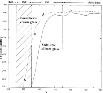
the vats depends on the length of the spindle. If the diameter of the vats is 100mm and the vats will be placed at 15mm from each other, the minimal translatable length of the spindle needs to be 460mm, which is shorter then 500mm and would thus work. 100mm is thus the right diameter for the vats. The vats are made of borosilicate glass since it has the required high optical specifications and is covered with a PDMS layer, which has high optical and anti-stick specifications.
Figure 22:Schematic view of the resin vats
Stepper motor control
The motors that are used in the EXZEED are the Nanotec stepper ST4209-1006B stepper motors. These are Nema 17 sized motors just like the motors used by Budel, although they have different specifications. (See the datasheet in Appendix 3). If the motors are working at the maximum current, there’s a maximum torque output for given rotation speeds. Applying a too high frequency of input steps, might cause the motor to skip them, or doesn’t allow the motor to reach full torque. This is because of self-inductance in the coils. The graph with the green line in the figure below displays the settings that are used within this project.
The EXZEED printer 39
Motor setup used for the printer
The motors are connected in bipolar mode. This means that the white and black COM cables shouldn’t be connected. The jumpers on motherboard should be set so that the motor will run in ½ step mode. Using a 24V bus voltage results in a maximum rotation speed of about 150RPM with a torque output of about 0.18Nm (See the orange and green line). More information about the choice for these settings is in Appendix 4.
Spindles
For the translations spindles will be used. They are available in different types: buttress, acme, ball screw, or square thread. The difference between the types is efficiency, price, force direction and bulkiness. Square thread spindles were chosen since they have high efficiency and precision, but not the bulkiness like ball screws have.
The lead of the spindles is chosen that the system with a motor with a maximum turning speed of 150 RPM can drive the system fast and precisely. In appendix 5 are calculations for different leads. Since a precision of 20 (half) steps per layer is acceptable for the Z-movement, a width a lead of 4mm will be the best choice for the Z-spindle. There wasn’t a nut-screw combination with this specification available, so a 2mm nut-spindle combination was bought. The other spindle was already available (20mm). For the x-spindle the acceleration setting is more important than the speed, since the acceleration will determine if the resin will be spilled out or not. The acceleration will be set by experimenting.
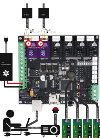
Arduino & motherboard
The printer’s motherboard works as a terminal for all incoming and out coming connections so all external components are provided with the right power and are controlled from the right pins of the microprocessor. They are equipped with fuses to prevent burning the circuits. Budel used a Ramps 1.4 motherboard that is placed on top of an Arduino Mega 2560. Since all printer firmware available are written for use on Arduinos equipped with these kinds of motherboards, using such a motherboard really eases building and setting up the firmware. The Ramps 1.4 has standard solderless terminals for Pololu stepper driver carriers, however other carrier boards can be
The EXZEED printer 41
Opto-endstops
The printer will be equipped with four opto-endstop sensors. They prevent the system to be blown apart when the stepper-motors skip steps and they determine the references for homing the printer.
Power supply
As written in the motor section, a 24V 15A power source will be used instead of the 12V power source that was used by Budel. It is connected to the power input on the Megatronics v3 board and is adjusted using a voltmeter to output exactly 24V using the small screw on it.
Firmware
There exist many firmwares that are developed to be used for 3D printing, although they all have their own properties. For DLP printing with Creation Workshop as the host software a firmware that works by communicating with G-code and M-code that is send over the serial port needs to be chosen. There are firmwares that do support acceleration control of the motors and there are firmwares that don’t. For this purpose a firmware with acceleration control needs to be chosen: too stiff movement will cause the material to spill out of the vats. Many information about firmwares can be found on the wiki on reprap.org (Reprap, 2015) The Marlin firmware (Fig. 25) is chosen, since it has full end stop support, is accelerated and can be PID tuned for achieving better speed & accuracy properties. On the forum of
Buildyourownsla.com there are many people that use the Marlin firmware. (Buildyourownsla.com, 2015)
Figure 25:Logo of the Marlin firmware
Host software
Tristram Budel used Creation Workshop (Fig. 26) as the host software. For building the multi material printer this host software will be used as well, since it is the only software that can control the motors and the beamer at the same time. It communicates with the printer using RS232 serial communication.
Figure 26: The Creation Workshop host software
Beamer
The beamer that is used in this project is a Benq PB7230 DLP beamer. It works at the XGA resolution (1024 *768) the beamer is modified to be able to have a shorter throw: Normal beamers can project only big images at a minimal distance of about 1,5m. For the purpose of 3D printing, the beamer needs to project a very small image at a very short distance. Installing a 5mm spacer between the lens assembly and the DMD chip did this. In Appendix 9 there is an image of the spacer. The spacer increases the object distance. How this works is described in Appendix 6. A side effect is that the edges of the projected image become a little bit blurry. The beamer will be turned upside-down: Normally a beamer projects a bit upward, and this would project light into the resin vat directly, which is not desired. A little cable is soldered to the beamer’s PCB to be able to operate it from outside the printer. Directly behind the light source there was a 3mm thick filter installed. This filter is removed since it is very likely that it blocks UV light. On the buildyourownsla.com forum there are many people suggesting to move the colour-wheel away so that it’s no longer in the light-path. It is likely that it blocks some UV light, although no one measured the influence of moving it away. For this project it isn’t removed yet since it doesn’t seem to be easy to do. The colour wheel shouldn’t be removed completely, since it will cause the beamer to fail because it measures the colour of the wheel to sync with the DMD.
Mirror
The mirror is needed to position the beamer horizontally instead of
The EXZEED printer 43 beamer. For the EXZEED an 85*101 400-600nm first surface mirror was used. The position and angle of the mirror are designed to be easy adjustable.
Vat array assembly
The vat array assembly, see the figure below, houses the resin vats and allows them to be moved horizontally. Each petri dish (1) is supported with three M3 screws. This way the position of the petri dishes can be adjusted to make the PDMS layer equal level, which is needed for multi-material
printing. These M3 screw are placed in self-taped holes in a Delrin sheet (2). Delrin is chosen since it’s well suitable for tapped holes. The horizontal movement of the dishes is limited by a 5mm thick Plexiglas sheet (3) with 105mm holes. Four linear-bearing housings (4) were screwed on top of this sheet. The 10 spring assemblies (5) were also screwed on top of this sheet. Through the bearings two 1000mm shafts were placed. These shafts were fixed to the body with four shaft supports (7) These supports have a very loose fit with the shafts, but through the supports bolts are mounted in order to adjust the position of the shaft. This is needed since high accuracy of the height is needed.
Figure 27: The vat array assembly
Vats
Petri dishes will be used as the resin vats. (Fig. 28) They have standard dimensions and don’t require a lot of effort to make and assemble. Petri dishes are sold in different materials. The best suitable material is borosilicate glass since it has a higher transmittance at low wavelengths. (Fig.29) High dishes were purchased and were filled with a +-2mm layer of Sylgard 184. After pouring the solution in the petri dishes the vats have to dry for at least two days on a flat surface at room temperature, or 45 minutes
at 100˚C. (Dow Corning, 2015) The downside of using this PDMS layer is that
it is considered to be a consumable so it needs to be replaced after a number 1
2 3
4 5
7
of prints. The thicker the layer, the longer it lasts. PDMS is sensible to temperature and isn’t completely chemically inert.
[image:44.499.90.261.228.382.2]Figure 28: 100mm Borosilicate Petri dishes (Duroplan) (Cloup, 2015)
Figure 29:Transmittance of borosilicate glass compared to normal glass
(Publiclab, 2013)
Passive tilting system with spring assemblies
The EXZEED printer 45 Figure 30: The spring assembly
Figure 31:The grasping of the petri dishes by the spring assemblies. Nuts with ‘1’ will be tight, nuts with ‘2’ will be loose to allow passive tilt
1
1 1
1 1
1 1
1 1
1 1
1
2 2
2
2 2
2
2
2
2
Platform assembly (Fig. 32)
The platform (1) needs to fit in the resin container, but should be big enough for the projection. The resin should stick to the platform, but should be able to be peeled-off after the print is completed. Experiences of other DLP printers say that anodized aluminium is a well suitable material since it has a rough but hard surface and doesn’t react with the resin. The platform hangs on a spacer (2) with 3 bolts. Without this spacer the Plexiglas support (4) would hit the shaft. The spacer is connected with one thick bolt (3) to the support. To limit the rotational freedom a small stick is placed on top of the spacer. On top of the spacer 3 M3 screws are placed. These are there for adjusting the angle of the platform with the platform support.
[image:46.499.84.414.241.501.2]A linear carrier was screwed to the backside of the support and placed on the linear guide (5). The nut housing of the z-spindle assembly was screwed to the floor of the support.
Figure 32: The platform assembly
1 2 3
The EXZEED printer 47
The body
[image:47.499.84.274.294.411.2]The body (Fig. 33) needs to be rigid and precise. The body is made of MDF, since MDF is very flat, cheap and can be laser cut. MDF is sold by standard thicknesses. 12mm was the closest to the desired thickness of 10mm. The thickness is needed to be rigid, but also to be able to drill screws in the side of the parts. The body was designed to have ‘fingers’ at the edges. This made assembling and positioning of the parts easy. The body is designed in a way that the corners between the parts are very close to 90˚. In the middle of the body there are two supports. (1) These are needed, because else the bending of the material would cause inaccuracy. In the picture below there are two holes in the backside. (2) These holes are covered with their opposite form. They are there to make it easy to remove the beamer and to adjust the screws for adjusting the height of the resin containers. The covers are removable to make it easier to laser cut holes needed for future parts. (Including vans, power lines etc.) The body was filled, sanded and painted afterwards to get a glossy black appearance.
Figure 33: The body
Logo
A logo and name was designed for the printer. (Fig. 34) EXZEED is the name, from ‘exceeding the boundaries’ of current DLP technology. It is written with a sigma, so some people will try to read is as a word that sounds like
‘succeed’. The printer has an X and Z-axis. The name sounds like the Dutch ’Ik zie het’. (I see it) The logo’s opposite shape contains arrows for the X and Z movement and the last character references to the triangular construction of the platform support. The last characters appear like ‘3D’.
Figure 34:The EXZEED logo
1 1 2
[image:47.499.90.347.534.594.2]Hood
The hood is made of 3mm thick orange PMMA since it blocks the strong light emitted by the beamer. The hood is also designed with ‘fingers’ since it eases the assembling. It has holes for the motor and for the switch.
Making the parts
The building of the printer was eased by the availability of laser cutters (Appendix 8) and 3D printers. (Appendix 9) These tools made it easy to make complex parts with a high accuracy. The aluminium hand knobs and the aluminium build platform were the only parts that were built manually. In the Appendix 10 there are descriptions about how all parts are made. The Solidworks files are available at the disk provided with this document.
Assembling
Conclusion 49
Conclusion
A 3D DLP printer with five moveable vats was designed and built, after the analysis of the 3D DLP principle. DLP printing uses a photo polymerisation process. There are two types of photo polymerization. Cationic and free radical. The one that’s of importance in this project is ‘free radical
polymerisation’. When a photo initiator is exposed to photon with the right energy, a free radical is released. Monomers will combine with this radical until another chain or radical closes the chain. The mobility of the monomers plays an important role and is influenced by the temperature and the number of functional groups of the monomer. Generally, the more functional groups, the more entangled the network of polymer will be, the slower the reaction, the tougher the material, the lower the density and the more uncured resin. The more functional groups, the less it is sensitive to oxygen inhibition. The higher the amount of light energy, the more photo-initiators are activated and the thicker the gradient will be. This gradient determines the layer thickness that should be used. A too thick mechanical configured layer thickness will result in semi cured-waxy objects and a too thin
Recommendations 53
Recommendations
The prototype that was realised in this project is not perfect yet. This is why the printer was designed to be easily upgradeable.
Problems
a) The printer that was build has a problem with a dangling spindle.
This spindle is only fixed on the motor side, but should also be fixed to the bottom of the body. The dangling causes a XY-movement of the platform that causes inaccuracy of the printed products.
b) The printer becomes hot on the inside because of the heat generated
by the beamer. A pocket air-condition combined with some computer fans could be the remedy.
c) The vats are a bit lower than expected. They were designed with
petri dishes with a height of 20mm, although the 15mm petri dishes were in stock and could be sent earlier. Higher vats would allow higher acceleration speeds for the horizontal movement.
Opportunities
a) The printer could be equipped with aquarium pumps to refill the
resin vats. The Megatronics v3 board could also control these.
b) A display showing the current layer that is printed could be added
easily. This is a standard feature of Marlin and the Megatronics board.
Future research
a) Experiments with the resin thickness and the building of
test-geometries are still left to do.
b) Also research has to be done to the amount of bleed in the XY plane.
c) Using a beamer is not really the best option for the light source in
DLP printing. It consumes a lot of power, generates a lot of heat, and outputs just a little amount of useful light for curing. The rest of the light will be transferred to heat which result in shrinkage. The beamer’s light output is not measured; this should be done to get more insight about the performance. Beamers using DLP chips with better specifications for 3D printing might be available. A Wood’s filter +IR filter could be installed in front of the beamer to filter out the unused wavelengths that cause heat.
d) The PDMS layer degrades by heat. This might become very unhandy
Hlocke on the website ‘projects, interests and etcetera’ described how to build them. (hlocke, 2015)
e) There are already people experimenting with LCD technology for 3D
printing. LCD displays with removed filters and removed backlights are used and replaced by UV LEDS and a Fresnel lens. LCD screens can be made very big and don’t need a lens system that blocks UV and causes unsharpness at the edges.
f) There are more things that need to be setup in the host software to
be able to print. This includes layer thickness and the movement of the motors to change the vats. Estimating the layer thickness requires many experiments and there’s just not enough time for that within the extend of this assignment. Motor controls for controlling the X-axis automatically can be setup in the custom G-code section. This can be used to setup the movement for multi-material printing. An overview of the G-code commands can be found on
Bibliography 55
Bibliography
[1] 3Dprinter.wikidot. (2011, 12 5). mono-oligomers. Retrieved 06 28,
2015 from 3dprinter.wikidot.com:
http://3dprinter.wikidot.com/mono-oligo-mers#toc0
[2] Anthony DiCarlo, S. M. (2015). Patent No. US 7450297B2. United
States of America.
[3] Batch, G. L., & Macosko, C. W. (1990). Oxygen inhibition in
differential scanning calorimetry of free radical polymerization.
Thermochimica Acta, 166, 185–198.
[4] Bucktownpolymers. (2013). Buck mix. Retrieved 06 28, 2015 from
Bucktownpolymers.de: http://bucktownpolymers.de/mixing-tutorials/standard-mix/
[5] Bucktownpolymers. (2013). Photoinitiators. Retrieved 06 28, 2015
from Bucktown Polymers:
http://bucktownpolymers.de/photoinitiatoren/?lang=en
[6] Budel, T. (2013, 7 14). DIY high resolution 3D DLP printer (3D SLA
printer). Retrieved 06 29, 2015 from Instructables:
http://www.instructables.com/id/DIY-high-resolution-3D-DLP-printer-3D-printer/
[7] Buildyourownsla.com. (2015). Homepage. Retrieved 06 30, 2015
from Buildyourownsla.com:
http://www.buildyourownsla.com/forum/
[8] Carbon3D. (2015). Clip Technology. Retrieved 06 30, 2015 from
Carbon3D: http://carbon3d.com
[9] Chong, J. S. ( 1969). Oxygen consumption during induction period of
a photopolymerizing system. Applied Polymer Science (13), 241.
[10] Ciba Specialty Chemicals. (2015). UV Photo initiators. Retrieved 06
28, 2014 from Ciba Specialty Chemicals:
http://www.mufong.com.tw/Ciba/ciba_guid/photo_uv_2.pdf
[11] Cloup. (2015). Boîtes de Pétri en verre Duroplan®. Retrieved 07 06,
2015 from Cloup.fr: http://www.cloup.fr/scat.php?scat_id=520
[12] Crivello, J. V., & Reichmanis, E. (2013, 9 25). Photopolymer Materials
and Processes for Advanced Technologies. Chemical Mater (26), pp.
533–548.
[13] Desimone, J. M., Ermoshkin, A., Ermoshkin, N., & Samulski, E. T.
(2014). Patent No. WO2014126837 A2. WO.
[14] Dow Corning. (2015). Sylgard 184 Datasheet. Retrieved 07 06, 2015
http://research.engineering.ucdavis.edu/ncnc/wp-content/uploads/sites/11/2013/05/Sylgard_184_data_sheet.pdf
[15] Hernandez, S. (2015). Creation Workshop. Retrieved 06 2015, 2015
from Envision labs: http://www.envisionlabs.net
[16] hlocke. (2015, 07 15). Diagram of a Flexvat. Retrieved 10 2015, 2015
from projects, interests and etcetera: http://projectsinterestsandetcetera.com
[17] Hopkinson, N., Haque, R., & Dickens, P. (2005). Rapid Manufacturing:
An Industrial Revolution for a Digital Age: An Industrial Revolution for the Digital Age . Chichester: John Wiley and Sons LTD.
[18] Horsey, J. (2014, 6 31). LittleRP Open Source SLA 3D Printer Unveiled
Ahead Of Crowd Funding Campaign (video). Retrieved 6 30, 2015 from Geeky Gadgets: http://www.geeky-gadgets.com/littlerp-open- source-sla-3d-printer-unveiled-ahead-of-crowd-funding-campaign-31-07-2014/
[19] Hull, C. (1993). Patent No. US 5236637. US.
[20] Idacavage, D. M. (2012, 09 27). Introduction to the Basics of UV/EB
Chemistry and Formulations. Retrieved 06 28, 2015 from
http://www.esf.edu/outreach/uvebwebinar/documents/Intro_Basi c_UV_curing2012_MJI.pdf
[21] Ji, L., Chang, W., Ming, C., & Nie, J. (2013). Photopolymerization
kinetics and volume shrinkage of 1,6-hexanediol diacrylate at
different temperature. Journal of Photochemistry and Photobiology A:
Chemistry, 252, 216–221.
[22] John, H., & Envisiontec. (2007). Patent No. US7195472 B2. US.
[23] Joyce, M. (2013). Patent No. US20130292862 A1. US.
[24] Krassenstein, E. (2015, 06 1). moonray dlp 3d printer. Retrieved 06
27, 2015 from 3dprint.com: http://3dprint.com/69812/moonray-dlp-3d-printer
[25] Lee, T. E., Sonny Jonson, E., Hoyle, C. E., & Guymon, C. A. (2004). The
effect of monomer structure on oxygen inhibition of (meth)acrylates
photopolymerization. Polymer , 6155–6162.
[26] Li, L., Gao, H.-W., Ren, J.-R., Cheng, L., Li, Y.-C., Zhao, J.-F., et al. (2007, 3 27). Binding of Sudan II and IV to lecithin liposomes and E. coli
membranes: insights into the toxicity of hydrophobic azo dyes. BMC
Structural Biology .
[27] Little RP. (2015). Little RP. Retrieved 06 30, 2015 from Little RP:
http://www.littlerp.com
[28] Mystamo. (2015, 3 15). $10 Top Down Build SLA. Retrieved 06 29,
2015 from Buildyourownsla:
Bibliography 57 http://en.nanotec.com/fileadmin/files/Datenblaetter/Schrittmotor en/ST4209/S/ST4209S1006.pdf
[30] PerkinElmer. (2015). Color Quench Correction in Scintillation
Proximity Assays. Retrieved 06 28, 2015 from PerkinElmer:
http://www.perkinelmer.de/pages/020/proximitynews/bead_infor mation/beadinformation_color_quench_correction.xhtml
[31] Pololu Robotics and Electronics. (2013). Datasheet of DRV8825.
Retrieved 06 30, 2015 from Pololu:
https://www.pololu.com/file/0J603/drv8824-drv8825-stepper-motor-driver-carrier-schematic-diagram.pdf
[32] Projector Central. (2015). BenQ PB7230 Projector. Retrieved 06 28,
2015 from Projector Central:
http://www.projectorcentral.com/BenQ-PB7230.htm
[33] Publiclab. (2013). UV-spectrometry. Retrieved 07 06, 2015 from
Publiclab: http://publiclab.org/wiki/uv-spectrometry
[34] Reprap. (2015). G-code wiki. Retrieved 07 07, 2015 from Reprap:
http://reprap.org/wiki/G-code
[35] Reprap. (2015, 5 18). List of Firmwares. Retrieved 2015 from
Reprap.org: http://www.reprap.org/wiki/List_of_Firmware
[36] Reprapworld. (2015). Ramps 1.4 - basic kit. Retrieved 06 30, 2015
from Reprapworld:
http://reprapworld.com/?products_details&products_id/53/cPath/ 1591_1609#.VZKY52CCPgQ
[37] Reprapworld. (2015). Software. Retrieved 07 2015, 2015 from
Reprapworld.com: http://reprapworld.com/?software
[38] Scholnik, A., El-Siblani, A., & John, H. (2006). Patent No. US7892474
B2. US.
[39] Solarbotics. (2015). Stepper Motor Basics. Retrieved 06 30, 2015
from Solarbotics:
http://www.solarbotics.net/library/pdflib/pdf/motorbas.pdf
[40] Spectra Group Limited. (2015). Photoinititators. Retrieved 06 28,
2015 from Spectra Group Limited:
http://www.sglinc.com/Home/LimitedHomepage/Photoinitiators.a spx
[41] Stoner, C. (2011, 07 8). Stepper Motor Voltages Explained. Retrieved
06 2015, 2015 from Selene:
http://www.selene.co/Blog/2011/07/stepper-motor-voltages-explained/
[42] Texas Instruments. (2015). About DLP Technology. Retrieved 07 28,
[43] Texas Instruments. (2015). DLP Technology. Retrieved 06 28, 2015 from Texas Instruments:
http://www.ti.com/lsds/ti/dlp-technology/dlp-technology-home.page
[44] Texas Instruments. (2015, 05). TI DLP Technology for 3-D printing.
Retrieved 06 28, 2015 from Texas Instruments: http://www.ti.com/lit/sg/dlpt019b/dlpt019b.pdf
[45] Venus Creator. (2015). Castable 3d printing resin. Retrieved 06 28,
2015 from Venus Creator:
http://www.venuscreator.com/3dp_resin.html/wax-like-castable-3d-printing-resin.html
[46] watsonstudios. (2013, 12 20). Tilt mechanism for my DLP printer.
Retrieved 07 6, 2015 from 3dprintforums:
http://www.3dprintforums.com/showthread.php?t=127
[47] Wikipedia: Metal-halide lamp. (2015). Wikipedia.org. Retrieved 06
28, 2015 from Metal-halide lamp:
https://en.wikipedia.org/wiki/Metal-halide_lamp
[48] Wikipedia: Photopolymer. (2015). Photopolymer. Retrieved 06 28,
2015 from wikipedia.org:
Appendix 1: Properties of monomer & oligomers 59
[image:59.499.103.338.170.653.2]Appendix 1: Properties of
monomer & oligomers
Table 1: Curing properties for various acrylates
Appendix 2: Properties of Photo initiators 61
[image:61.499.88.389.166.629.2]