warwick.ac.uk/lib-publications
A Thesis Submitted for the Degree of PhD at the University of Warwick
Permanent WRAP URL:
http://wrap.warwick.ac.uk/109581
Copyright and reuse:
This thesis is made available online and is protected by original copyright.
Please scroll down to view the document itself.
Please refer to the repository record for this item for information to help you to cite it.
Our policy information is available from the repository home page.
COPYRIGHT
Reproduction of this thesis, other than as permitted under
the United Kingdom Copyright Designs and Patents Act
1988, or under specific agreement with the copyright
holder, is prohibited.
This copy has been supplied on the understanding that it
is copyright material and that no quotation from the thesis
may be published without proper acknowledgement.
REPRODUCTION QUALITY NOTICE
The quality of this reproduction is dependent upon the
quality of the original thesis. Whilst every effort has been
made to ensure the highest quality of reproduction, some
pages which contain small or poor printing may not
reproduce well.
Previously copyrighted material (journal articles, published
texts etc.) is not reproduced.
TECHNIQUES TO NON-DESTRUCTIVE TESTING
OF COMPOSITES
BY: M.Z. ISKANDARANI
(B.Eng (Hon.), M.Sc, AMIEE (GB), MIEEE (USA))
Submitted for the degree of
DOCTOR OF PHILOSOPHY in Engineering
at
University of Warwick
Advanced Technology Centre
Department of Engineering
Coventry, UK
DECLARATION
I declare that all the work appeared in this thesis was carried out by myself
unless otherwise acknowledged in the text.
r
ACKNOWLEDGEMENTS
I would like to express my gratitude and thanks to my excellent supervisor, Dr. Gordon F.
Smith for the Total confidence that he placed in me, the full academical and financial support
and for his constant encouragement and help.
I would also like to thank Dr. Peter T. Davies (Director of the Advanced Technology Centre)
for supporting this project and for valuable comments and disscussions.
My appreciation extends to all the staff of the Advanced technology Centre and Warwick
Manufacturing Group for their help and contribution, and to the following companies for their
co-operation, collaboration and technical support:
(1) SOFRATEST U.K (SPEEDTRONIC DIVISION).
(2) AGEMA INFRARED SYSTEMS.
(3) NCS (NEURAL COMPUTER SCIENCES).
(4) ROVER GROUP.
(5) OMETRON.
(6) COMFORD DESIGN LIMITED.
My personal appreciation goes to Dr.Mike Arrington (SOFRATEST U.K) and Alan Grant
(AGEMA INFRARED SYSTEMS) for their personal contribution to this work.
However, my everlasting gratitude and thanks to Ian Pearson of the Advanced Technology
Centre for many hours that he spent with me correcting and editing this document and for his
SUMMARY
Composites manufactured for applications in the automotive industry were non-destructively
tested to determine damage using the following techniques:
(1) Low frequency tapping.
(2) High frequency (C-Scan).
(3) Visual imaging.
(4) Low and high temperature pulse video thermography.
Various levels of impact energy were applied to the following types of composites
(I) RIM: Reaction injection moulded.
(II) Woven Glass.
(III) GMT: Glass mat thermoplastic.
Some interesting results were obtained which could be explained through analytical and
numerical modelling. These results were analyzed through developments of the following
algorithms:
(a) A novel approach to damage detection using wavelength variation and sequence grouping
software.
(b) Correlation of the various NDT techniques through one mathematical equation and
software.
(c) The introduction of the uniformity factor concept and software to account for variations
among samples quality in relation to experimental results.
(d) The development of smart classification system together with standard neural network
algorithms for prediction and classification.
CONTENTS
CHAPTER 1: INTRODUCTION ... 1
CHAPTER 2: OBJECTIVES ...2
CHAPTER 3: C O M PO SIT E S...4
CHAPTER 4: DAMAGE IN COMPOSITES ... 4.1 Introduction ...8
4.2 Impact Damage ... 12
4.3 Impact Damage: A Closer Look ... 16
4.4 Impact Damage: An Energy Bond M o d el...20
CHAPTER 5: DESTRUCTIVE AND NON-DESTRUCTIVE TEST TECHNIQUES 5.1 Introduction ...31
5.2 NDT: A F o c u s ... 33
CHAPTER 6: SONIC AND ULTRA SONIC TEST TECHNIQUES 6.1 Low Frequency Vibrational T e c h n iq u es... 36
6.2 Tapping Method: Mathematical Model ... 45
6.3 Ultrasonic T ech n iq u es... 54
6.4 Acoustic Emession And A cousto-U ltrasonics... 70
CHAPTER 7: VISUAL AND OPTICAL TECHNIQUES 7.1 Introduction ...79
7.2 Infrared and Thermal Recording ... 81
7.3 Optical T ech n iq u es... 100
7.4 Microwave Techniques ... 107
CH A PTER 8: NDT DATA: INTERPRETATION AND ANALYSIS TECHNIQUES
8.1 Introduction ... 117
8.2 Classification Techniques: A R e v ie w ... 118
8.3 Adaptive Pattern Recognition Using Artificial Neural Networks 129 8.4 Smart Classification And Neural Network Algorithms . . . 138
CH A PTER 9: EXPERIMENTAL ARRANGEMENTS 9.1 Introduction ... 152
9.2 Specimen Design and Structural P ro c e ssin g ... 152
9.3 Structural Damage: Impact Approach ... 154
9.4 Non-Destructive Testing T e c h n iq u e s... 156
9.5 Processing and Analysis S y s te m ... 163
CH A PTER 10: EXPERIMENTAL R E SU L T S... 165
CH A PTER 11: ANALYSIS AND DISSCUSSION ... 11.1 Introduction ... 214
11.2 Low Frequency Techniques - Electronic Tap Testing . . . 214
11.3 High Frequency Technique: Ultrasonic C -S c a n ... 227
11.3 Visual T echniques...245
11.4 Fast Classification And Parameters Prediction... 289
CH A PTER 12: C O N C L U SIO N S...304
CH A PTER 13: IMPROVEMENTS, DEVELOPMENTS AND FUTURE WORK . 13.1 Introduction ... 306
LIST OF FIGURES
Figure 2.1 An intelligent image capturing, processing and recognition system [214], 3
Figure 3.1 Hybridization of composites [5], 5
Figure 3.2 Concepts of material design [5]. 6
Figure 3.3 Process employed in the design of composites [6]. 7
Figure 4.1 Energy Band Model. 21
Figure 4.2 Geometrical and Electrical Transformations. 25
Figure 4.3 Field function of interactive energy states. 30
Figure 6.1 Low frequency tapping system [46]. 37
Figure 6.2 Frequency response of a tap tested CFRP tubes [46]. 38
Figure 6.3 Measurement and modelling of composite mechanical impedance. 43
Figure 6.4 Response of defective and non-defective structures to tappings [46]. 44
Figure 6.5 Response system block diagram. 46
Figure 6.6 Shape function for 3mm GMT (Perpendicular). 54
Figure 6.7 Shape function for 3mm woven glass. 54
Figure 6.8 An ultrasonic A-scan system [50], 62
Figure 6.9 B-scan ultrasonic system [50]. 64
Figure 6.10 C-scan ultrasonic system [50]. 66
Figure 6.11 Acoustic Emission system and Defect frequency response spectrum [60-61]
72
Figure 6.12 Stress Waves interpretation through ring and event counting [64]. 73
Figure 6.13 Effect of load on stress wave amplitudes in composites [64], 74
Figure 6.14 AE response to different types of composite damage [64]. 77
Figure 7.1 Luminosity function used in visual NDT [41], 81
Figure 7.2 IR emissions and possible wavelengths recordings, reproduced from KODAK
film company, U.K. 83
F%ure 7.3 Types and structures of Liquid Crystals [106]. 85
Figure 7.4 Concept of Thermal Colour OR and its response.Reproduced from the work at
SIBER HEGNER Ltd, U.K. 87 '
Figure 7.5 Visual processing of Liquid Crystals profile [103], 89
Figure 7.6 Passive and Active Thermography [79-82]. 96
Figure 7.7 Generation of holograms using Holography [124], 102
Figure 7.8 Generation of holograms using Shearography [124], 103
Figure 7.9 X-rays backscattering concept [137], 106
Figure 7.10 The CAT system [137]. 107
Figure 7.11 Measurement o f specimen reflection coefficient using Microwaves [132]. 109
Figure 7.12 Detection of defects using Microwaves in Transmission mode [132], 110
Figure 7.13 A look-into microwave detecting system [132]. 111
Figure 8.1 Classification and Discrimination concept. 120
Figure 8.2 Discrimination using LC classification. 120
Figure 8.3 Classification of different categories using linear surfaces. 123
Figure 8.4 Use o f NNC as a discriminating method. 124
Figure 8.5 Misclassification as a drawback in NNC. 125
Figure 8.6 Illustration of the structural technique. 128
Figure 8.7 Concept of information processing using Neural interconnections. 134
Figure 8.8 Representation of neuron activity. 135
Figure 8.10 Unsupervised learning mechanism. 137
Figure 8.11 Supervised learning mechanism. 138
Figure 8.12 Smart classification system block diagram. 139
Figure 8.13 Data file source matrix. 140
Figure 8.14 Matrix-Column classification concept. 143
Figure 8.15 Uniformity Factor concept. 144
Figure 8.16 The overall Smart Classification block diagram. 146
Figure 8.17 Back Propagation method. 148
Figure 9.1 Drop Weight Impacting System. 155
Figure 9.2 Design and shape of used impact weights. 156
Figure 9.3 An Electronic Tapping System. 158
Figure 9.4 The scanning arrangement adopted in the experiments. 159
Figure 9.5 The Ultrasonic C-scan system used in the experiments. 160
Figure 9.6 Dual Visualand IR Imaging setup. 161
Figure 9.7 High Temperature PVT setup. 161
Figure 9.8 Low Temperature PVT set up. 162
Figure 10.1 Low Frequency tapping response of 3mm and 5mm W.Glass. Top: Experimental.
Bottom: Fitted. 166
Figure 10.2 Low Frequency tapping response of 3mm GMT. Top: Experimental. Bottom:
Fitted. 167
Figure 10.3 Low Frequency taping response of 2mm RIM. Top: Reference factor. Bottom:
Average factor. 168
Figure 10.4 Low Frequency tapping response of 5mm RIM. Top: Experimental. Bottom:
Figure 10.5 Effect of impact energy on C-Scan response of W.Glass. Top: 3mm. Bottom:
5mm. 170
Figure 10.6 C-Scan images of 5mm W.Glass impacted at 14.3J using Search Through
Technique. 171
Figure 10.7 C-Scan images of 5mm W.Glass impacted at 7.14J using Search Through
Technique. 172
Figure 10.8 C-Scan images of 5mm W.Glass impacted at 4.76J using Search Through
Technique 173
Figure 10.9 C-Scan images of 5mm W.Glass impacted at 28.6J using Search Through
Technique. 174
Figure 10.10 C-Scan images of 5mm W.Glass with a hole drilled through it using Search
Through Technique. 175
Figure 10.11 C-Scan of A W.Bone. Left: Inner parts. Right: Outer parts. 176
Figure 10.12 First stage classification of 5mm W.Glass impacted at 4.76J and tested using
Low Temperature Visual Camera. 176
Figure 10.13 First stage classification of 5mm W.Glass impacted at 7 .14J and tested using
Low Temperature Visual Camera. 177
Figure 10.14 First stage classification of 5mm W.Glass impacted at 14.3J and tested using
Low Temperature Visual Camera. 177
Figure 10.15 First stage classification of 3mm W.Glass impacted at 4.76J and tested using
Low Temperature Visual Camera. 178
Figure 10.16 First stage classification of 3mm W.Glass impacted at 7.14J and tested using
Low Temperature Visual Camera. 178
Figure 10.18
Figure 10.19
Figure 10.20
Figure 10.21
Figure 10.22
Figure 10.23
Figure 10.24
Figure 10.25
Figure 10.26
Figure 10.27
Figure 10.28
Figure 10.29
Figure 10.30
Low Temperature Visual Camera. 179
Thw O.I.W.V. search through technique applied to 5mm RIM impacted at 28.6J
and 42J. 180
The O.I.W.V. search through technique applied to 5mm RIM impacted at 14.3J
and 30.8J. 181
The O.I.W.V. search through technique applied to 5mm RIM impacted at 28.6J
and 28.6J with load angle. 182
The O.I.W.V. search through technique applied to 5mm RIM impacted at 47.61
and 47.6J with reflective paint. 183
The O.I.W.V. search through technique applied to 5mm RIM impacted at 55.6J
with reflective paint and part extraction. 184
Visual first stage classification of 5mm RIM. (Reference Sample). 185
Visual first stage classification of 5mm RIM impacted at 14.3J and 30.8J.
185
Visual first stage classification of 5mm RIM impacted at 28.6J and 28.61 with
load angle. 186
Visual first stage classification of 5mm RIM impacted at 28.6J and 42J.
186
Visual First stage classification of 5mm RIM impacted at 47.6J and 47.6J
187
Visual first stage classification of 5mm RIM impacted at 55.6J with reflective
paint and part extraction. 187
Visual second stage classification of 5mm RIM. (Reference sample). 188
Figure 10.31
Figure 10.32
Figure 10.33
Figure 10.34
Figure 10.35
Figure 10.36
Figure 10.37
Figure 10.38
Figure 10.39
Figure 10.40
Figure 10.41
Figure 10.42
Figure 10.43
Figure 10.44
188
Visual second stage classification of 5mm RIM impacted at 28.6J and 28.6J
with load angle. 189
Visual second stage classification of 5mm RIM impacted at 28.6J and 42J.
189
Visual first stage classification of 5-layers, 5mm RIM. 190
Visual First stage classification of 10-layers, 5mm RIM. 190
Visual first stage classification o f 5mm RIM with plastic inclusions. 191
Visual first stage search through classification of 2mm RIM impacted at
4.76J. 191
Visual first stage classification of 2mm RIM impacted at 7.14J. 192
Visual first stage classification of 2mm RIM impacted at 14.3J. 192
Images of the I.I.W.V. technique applied to 5mm RIM impacted at 28.6J and 421.
(Light source 1). 193
Images of the I.I.W.V. technique applied to 5mm RIM impacted at 14.3J and
30.8J (shown). (Light source 1). 194
Images of the I.I.W.V. technique applied to 5mm RIM impacted at 28.6J and
28.6J with load angle (shown). (Light source 1). 195
Images of the I.I.W.V. technique applied to 5mm RIM impacted at 28.6J and
28.6J with load angle (both shown). (Light source 2). 196
Images of the I.I.W.V. technique applied to 5mm RIM impacted at 47.6J and
47.6J with reflective paint. (Light source 1). 197
Images of the I.I.W.V technique applied to 5mm RIM impacted at 55.6J with
Figure 10.45
Figure 10.46
Figure 10.47
Figure 10.48
Figure 10.49
Figure 10.50
Figure 10.51
Figure 10.52
Figure 10.53
Figure 11.1
Figure 11.2
Figure 11.3
Figure 11.4
Images of the I.I.W.V. technique applied to 5mm RIM with reflective paint and
part extraction. (Cycles 7-12, light source 1). 199
Thermal Visual Imaging applied to detect damage in 5mm RIM impacted at 28.6J
& 42J, 14.3J & 30.8J, 28.6J & 28.6J with load angle. 200
First stage classification of 5mm RIM tested using High Temperature Visual
Imaging. (Reference sample). 201
First stage classification of 5mm RIM impacted at 28.6J and 42J and tested using
High Temperature Visual Imaging. 201
First stage classification of 5mm RIM impacted at 14.3J and 30.8J and tested
using High Temperature Visual Imaging. 202
First stage classification of 5mm RIM impacted at 28.6J and 28.6J with load
angle and tested using High Temperature Visual Imaging. 202
The I.I.W.V. technique applied to 5mm RIM (with reflective paint) and 5mm
W.Glass impacted at 55.6J and 28.6J respectively and tested using High
Temperature PVT. 203
The I.I.W.V. technique applied to 3mm Perpendicular and Parallel GMT
impacted at 14.3J and tested using High Temperature PVT. 204
The I.I.W.V. technique applied to W.Bone tested using High temperature
PVT. 205
Tapping damage detection system. 219
Comparison between responses of 3mm GMT and W.Glass to tapping. 221
Curve fit for figure 11.2. 221
Comparison between Tap tested 3mm composites. 224
Curve fit for figure 11.4. 225
Figure 11.6 The complete tap testing and classification system. 226
Figure 11.7 Comparison between the response of 3mm & 5mm 4.76J damaged W.Glass to
C-scan. 229
Figure 11.8 Comparison between the response of 3mm & 5mm 7.14J damaged W.Glass to
C-scan. 229
Figure 11.9 Comparison between the response of 3mm & 5mm 14.3J damaged W.Glass to
C-scan. 229
Figure 11.10 Comparison between the effect of a 28.6J impact and hole on the integrity of
5mm W.Glass component. 230
Figure 11.11 Damage detection in a W.Bone using C-scan. 230
Figure 11.12 the human visual spectrum. 232
Figure 11.13 The Tristimulus functions. 234
Figure 11.14 Cone relative sensitivity spectrum. 235
Figure 11.15 Cone spectral sensitivity curve. 235
Figure 11.16 The Optical Map. 236
Figure 11.17 Relationship between Damage level and C-scan image intensities as a function
of impact energy in 5mm W.Glass. 238
Figure 11.18 Relationship between Damage level and Impact energy in 5mm W.Glass using
C-scan. 239
Figure 11.19 Effect of impact energy on the size if defect in 3mm W.Glass. 239
Figure 11.20 5mm W.Glass C-scan output signals, the component suffered a 28.6J impact and
a drilled hole. 241
Figure 11.21 A search Through Technique applied to the C-scanned 5mm W.Glass with 28.6J
Figure 11.23
Figure 11.24
Figure 11.25
Figure 11.26
Figure 11.27
Figure 11.28
Figure 1 1.29
Figure 11.30
Figure 1 1.31
Figure 1 1.32
Figure I 1.33
Figure 11.34
Figure 11.35
Figure 11.22 Detection of level and direction of damage in a C-scan image of 3mm W.Glass
using the Uniformity Factor algorithm. 242
Curve fit for figure 11.22. 243
Using the Uniformity Factor algorithm to establish defect level and orientation
in 5mm W.Glass through C-scans. 243
Curve fit for figure 11.24. 244
Visual detection of damage (4.76J) in W.Glass using Matrix- Column search
through algorithm. 246
Visual detection of damage (7.14J) in W.Glass using Matrix- Column search
through algorithm. 247
Visual detection of damage (14.3J) in W.Glass using Matrix- Column search
through algorithm. 247
Effect of impact energy on the visual response of 3mm W.Glass . 248
Effect of impact energy on the visual response of 5mm W.Glass. 248
Correlation between C-scan & Visual detection of damage(4.76J) in 5mm
W.Glass. 249
Correlation of C-scan & Visual detection of damage (4.76J) in 3mm W.Glass.
250
Correlation between C-scan & Visual detection of damage (7.14J) in 5mm
W.Glass. 250
Correlation of C-scan & Visual detection of damage (7.14J) in 3mm
W.Glass. 251
Correlation of C-scan & visual detection of damage (14.3J) in 5mm W.Glass.
Figure 11.36 Correlation of C-scan & Visual detection of damage (14.3J)in 3mm W.Glass.252
Figure 11.37 The Classifying Optical Map (COM). 255
Figure 11.38 The Damage Classifying Function (DCF). 257
Figure 11.39 Visual damage detection in 5mm RIM. 258
Figure 11.40 Effect o f impact energy on the visual response of 5mm RIM. 259
Figure 11.41 Effect of impact energy on the visual response of 2mm RIM. 260
Figure 11.42 Comparison between the responses of damaged (4.76J), 5mm thick RIM &
W.Glass. 260
Figure 11.43 Comparison between the responses of damaged (7.14J), 5mm thick RIM &
W.Glass. 261
Figure 11.44 Comparison between the responses of damaged (14.3J), 5mm thick RIM &
W.Glass. 261
Figure 11.45 Effect of impact damage on the uniformity of a 5mm RIM component (ROW
SPREAD), refer to figure 11.26. 262
Figure 11.46 Curve fit to figure 11.45. 262
Figure 11.47 Effect of impact damage on the uniformity of 5mm RIM component (COLUMN
SPREAD) , refer to figure 11.26. 262
Figure 11.48 Curve fit for figure 11.47. 263
Figure 11.49 Effect of using different optical sources and impact energy (28.6J) on detection
of damage level in 5mm RIM component. 264
Figure 11.50 Effect of application of same impact energy (figure 11.49) at an angle on level
of damage induced in 5mm RIM component using different optical sources.
264
Figure 11.52
Figure 11.53
Figure 11.54
Figure 11.55
Figure 11.56
Figure 11.57
Figure 11.58
Figure 11.59
Figure 11.60
Figure 11.61
Figure 11.62
on the detection of damage in 5mm RIM (refer to figure 11.50). 265
Effect of applying 42J impact energy and use of different optical sources on
damage detection in 5mm RIM. 265
Effect of painting (reflective coating) a 47.6J impact damaged component on
limiting the depth o f detection in 5mm RIM (refer to figure 11.50). 266
Effect of increasing the impact energy (55.6J) with part of the component
surface extracted due to impact on depth of detection in 5mm reflective painted
RIM. 266
Effect of impact energy on damage spread. 267
The T-MAP. The range of values corresponds to pixel intensities. 269
Application of I.I.W.V. to damage detection (28.6J & 42J) in 5mm RIM tested
using high temperature source. (Cycles 1-4). 270
Application of I.I.W.V.to damage detection (28.6J & 42J) in 5mm RIM using
high temperature source. (Cycles 5-8). 271
Application of I.I.W.V. to damage detection (28.6J & 42J) in 5mm RIM using
high temperature source. (Cycles 9-12). 272
Application of I.I.W.V. to damage detection (28.6J & 42J) in 5mm RIM using
high temperature source. (Cycles 13-16). 273
Application of I.I.W.V. to damage detection (28.6J & 28.6J applied at an angle
to the normal) in 5mm RIM using high temperature source.
(Cycles 1-4). 274
Application of I.I.W.V. to damage detection (28.6J & 28.6J applied at an angle
to the normal) in 5mm RIM using high temperature source.
Figure 11.63
Figure 11.64
Figure 11.65
Figure 11.66
Figure 11.67
Figure 11.68
Figure 11.69
Figure 11.70
Figure 11.71
Figure 11.72
Figure I 1.73
Application of I.I.W.V. to damage detection (28.6J & 28.6J applied at an angle
to the normal) in 5mm RIM using high temperature source.
(Cycles 9-12). 276
Comparison between the effect of 28.6J and 42J impact energies on the level of
damage in 5mm RIM. (Refer to figures 11.57-11.60). 278
Comparison between the effect of 28.6J and 28.6J applied at an angle to the
normal on the level of damage in 5mm RIM. (Refer to figures 11.61-11.63).278
Classification of damage in 5mm RIM impacted at 55.6J and tested using High
Temperature PVT. (Refer to figure 10.51). 280
Using the uniformity factor to detect damage in 5mm RIM impacted at 55.6J by
evaluating rate of energy propagation in a High Temperature PVT test.
280
Modelling of energy pulse propagation in 5mm RIM impacted at 55.6J with part
of the component removed. 281
Classification of damage in 5mm W.Glass impacted at 28.6J using High
Temperature PVT. (Refer to figure 10.51). 283
Application of the uniformity factor to detect damage in 5mm W.Glass impacted
at 28.6J by evaluating the rate of energy pulse propagation in High
Temperature PVT test. 284
Classification of damage in perpendicular 3mm GMT impacted at 14.3J and
tested using High Temperature PVT. (Refer to figure 10.52). 285
Application of the uniformity factor to damage detection in perpendicular 3mm
GMT impacted at 14.3J using H.T.P.V.T. test. 285
Figure 11.74
Figure 11.75
Figure 11.76
Figure 11.77
Figure 11.78
Figure 11.79
Figure 11.80
Figure 11.81
Figure 1 1.82
Figure 11.83
Figure 1 1.84
Figure 1 1.85
using High Temperature PVT. (Refer to figure 10.52). 286
Application of the uniformity factor to damage detection in 3mm parallel GMT
impacted at 14.3J using H.T.P.V.T. test. 286
Classification of damage in W.Bone using High Temperature PVT. (Refer to
figure 10.78). 287
Application of the uniformity factor to damage detection in W.Bone by
evaluating the rate of energy pulse propagation in High Temperature PVT
test. 287
Low Temperature PVT applied to an undamaged 5mm RIM component with two
different thermal ranges. 290
Low Temperature PVT applied to 5mm RIM impacted at 42J and tested at two
thermal ranges after coating with absorbing paint. 291
Low Temperature PVT applied to 5mm RIM impacted at both 28.6J and 42J
with the sample black painted. Notice the larger size of the cold spot in
proportion to higher impact energy (42J). 292
Low Temperature PVT applied to 5mm RIM impacted at 28.6J with the load
applied at angle.Two thermal ranges. 294
Low Temperature PVT applied to 5mm RIM impacted at 28.6J. 295
Low Temperature PVT applied to 5mm RIM impacted at 55.6J and painted with
reflective paint. 296
Low temperature applied to 5mm W.Glass impacted at 28.6J. 297
Neural Networks prediction of the effect of impact energy on the normalized
response of 5mm RIM. (Complete cycle). 298
response of 5mm RIM. (first cycle). 298
Figure 11.86 Neural Network prediction of effect of impact energy on the normalized response
of 5mm RIM.(Second cycle ).
299
Figure 11.87 Neural Network prediction of effect of impact energy on the normalized response
of 5mm RIM. (Third cycle). 299
Figure 11.88 Neural Network prediction of effect of impact energy on the normalized response
of 8mm RIM. (Complete cycle). 300
Figure 11.89 Neural Network prediction of effect of impact energy on the normalized response
of 8mm RIM.(First cycle). 300
Figure 11.90 Neural Network prediction of effect of impact energy on the normalized response
of 11mm RIM. (Complete cycle). 301
Figure 11.91 Neural Network prediction on effect of impact energy on the normalized
response of 11mm RIM. (First cycle). 301
Figure 1 1.92 Relationship between threshold impact damage energy and component
thickness. 303
Figure 13.1 An advanced impact system. 307
Figure 13.2 An accurate electronic tapping device. 310
LIST OF TABLES
Table 6.1: Ultrasonic Interaction. 61
Table 7.1: Comparison of NDT techniques. 116
Table 10.1: Image Decision Data (RIM). 206
Table 10.2: Image Decision Data (W.Glass). 207
Table 10.3: Neural Network Prediction Data. 208
Table 10.4: Neural Network Training Data (W.Glass). 209
Table 10.5: Neural Network Training Data (RIM). 210
Table 10.6: Neural Network Training Data (GMT). 213
Table 11.1: Comparison of composites. 222
NOMENCLATURE
E, 5, E,h ErZ.Ç
r.
e
w
g dL f K„ Kc d U.p.q E h PApplied impact energy.
Defect energy, i= l....n.
Balancing energy factors accounts for frictional forces.
Impulse functions.
Threshold Energy.
Response energy.
Complex geometrical plans.
Polar coordinates.
Complex potential plan.
Complex potential variables.
Distance between energy states.
Length of an energy state.
Field function.
Effective contact stiffness.
Stiffness over good area.
Stiffness over defective area.
Defect diameter.
Constants depend on effective boundary conditions.
Flexural modulus of a material and modulus of elasticity.
Depth of a defect.
X
y.. y2 :
a , (3 :
^G eneral •
Kref
Vef* Lvg’ f
IK, X
c
M
P(x) :
4 a 4s 4 z r T I V T N f Ea
Input signal-low frequency model.
Output signals-low frequency model.
Gain functions.
General normalized response factor-low frequency model.
Normalized time response of low frequency tapping model.
Normalized average time response o f low frequency tapping.
Multiplication function-low frequency model.
Reference, average and defect time responses-low frequency.
Differential parameters of tolerance-low frequency model.
Acoustic velocity.
Poissons ratio.
Pressure amplitude.
Absorption coefficient.
Scattering coefficient.
Attenuation coefficient.
Acoustic impedance.
Reflection coefficient
Transmission coefficient.
Acoustic energy.
Analogue voltage.
Decay time.
Number of ring counts.
Transducer resonant frequency.
a b TD TE L
Q
L’ T0
e„ P r v hp K I(v) g(X) X,Wj
n
h(X) Tcproportionality constant.
Distribution characteristic constant.
Thermal diffusivity.
Thermal effusivity.
Material thickness.
Heat flux.
Radiant emittance.
Atmosphere transmission coefficient.
Object emissivity.
Atmosphere radiant emittance.
Object radiant emittance.
Absorbed radiation.
Reflected radiation.
Transmitted radiation.
Frequency of radiation.
Plank’s constant.
Boltzmans constant.
Intensity of radiation.
decision discriminating function-LC.
Input vector.
Weight vector.
Bias value.
Classification function-NNC.
S, Th q,
s
W„, C, fT hT g(x) h, e, o t,r
0 th, Slh L, AP N, Nh D,Grouped classification sequences.
Amplitude factor.
Normalizing factor.
Hybrid column matrix.
Quantizing vector.
Data source.
Weight or response factor.
Grouped subsequences.
Uniformity factor-column.
Uniformity factor-row.
Activation classification function.
Hidden layer(s).
Vector of errors.
Output layer vector(s).
Target activation of output layer.
Learning rate.
Momentum factor.
Threshold function.
Threshold level sequence.
Optical source.
Appearance function.
Number of defective layers-low temperature.
Number of defective layers-high temperature.
CHAPTER 1
INTRODUCTION.
C o m p o site s a re in c re a sin g ly b ein g u sed a s s tr u c tu r a l m a te ria ls. O ne o f th e
m a jo r a d v a n ta g e s o f com posite m a te ria ls is th e ir a b ility to be ta ilo re d to m e e t
c e r ta in ap p lic a tio n s. T h u s, a p a rtic u la r type o f fibre a n d m a trix ca n be u s e d to
p ro d u c e co m p o n en ts a c q u irin g d ifferen t lay -u p s, th ic k n e sse s a n d v olum e
fra c tio n s . This im p lies t h a t a defect w hich is c o n sid e re d to be critic a l in one
c o m p o n e n t m ig h t be to ta lly acceptable in a n o th e r. H ence, s e ttin g q u a lity
c o n tro l a n d in sp e c tio n s ta n d a r d s is a v ery com plex t a s k , and is n o t m ad e a n y
s im p le r o r econom ical due to th e d iffe re n t N D T te c h n iq u e s, each of w h ich is
c a p a b le o f d e te c tin g c e rta in defects. T o g eth er w ith em ploying s ta n d a r d b u t
v a r ia b le in te rp re ta tio n m eth o d s, efforts h av e been d ire c te d to w ard b a la n c in g
th e c o s t a n d co m plexity o f a n in sp ectio n te c h n iq u e a g a in s t th e q u a lity of
in fo rm a tio n o b ta in e d an d th e flexibility of th e te c h n iq u e in d e te c tin g v a rio u s
ty p e s o f defects.
In th e a u to m o tiv e in d u s try th e re is a n eed to m a n u fa c tu re w ith la rg e r
p ro d u c tio n ra te b u t tig h te r q u a lity control w hich re q u ire s inspection te c h n iq u e s
w ith h i g h e r speed a n d b e tte r re so lu tio n w ith m ore in tellig en ce a n d accu racy
c o m p a re d to th e c u r r e n t co n v en tio n al ones. T h is w ork w ill be looking a t p a s t,
CHAPTER 2
OBJECTIVES.
As a so lu tio n to th e p roblem s a sso c ia te d w ith N D T a n d its ap p lic a tio n in th e
a u to m o tiv e in d u s tr y , th e re is a n eed to e sta b lish a n in te llig e n t a n a ly sis sy stem
coupled to a p o rta b le detectio n e n v iro n m e n t th a t un ifies all d iffe re n t ty p e s of
in p u ts a n d a u to m a tic a lly co n sid ers v a rio u s fib re /m a trix c o m b in atio n s w h ich
le a d s to e lim in a tio n o f any a m b ig u ity re g a rd in g defect se v e rity a n d its effect on
th e co m p o n en t u n d e r co n sid eratio n . T h is su g g e sts th e u se o f a n im ag in g
sy stem .
W e propose t h a t conversion o f v a rio u s d a ta s tru c tu re s a n d im ag es in
co n ju n ctio n w ith smart classification (a specially devised fin g e r p rin tin g
a lg o rith m b a se d o n p a tte r n reco g n itio n tech n iq u es) a n d neural networks
(p a ra lle l, h ig h ly in te rc o n n e c te d sy ste m s m ade o f m a n y in d iv isib le p ro cessin g
u n its in te ra c tin g w ith ea c h o th e r v ia a d a p tiv e w eig h ts) to g e th e r w ith
wavelength variations (in co rp o ratio n o f d iffe re n t e n erg y so u rces to u ncover
th e p resen ce o f d a m a g e ) to be a p ro m isin g sy stem for n o n -d e stru c tiv e te stin g .
F ig u re 1.1 show s s u c h a sy stem . T h is a u to m a te d im ag e c a p tu rin g sy stem
p o sse ss th e follow ing m ain c h a ra c te ris tic s :
(1) T h e a b ility to e x tra c t im p o rta n t in fo rm atio n from a b ac k g ro u n d of
ir r e le v a n t d e tails.
(2) T he c a p a c ity to le a rn from p a s t ex p erien ce a n d ap p ly its
k n o w led g e to new d iffe re n t s itu a tio n s.
[image:32.586.1.542.12.659.2]I .it s.'mediale-level processing
Representation
Segmentation and
description
r
i
i
J
k
W
-
d
z
i i i
, .
u u
Preprocessing r '—
!
i
1 |
1 . _ i
1 1 i
problem
f t
* I
Knowledge base
i !
»
Recognition and interpretation domain
Image |/1— f \
acquisition |\ j — ! !
1 1
Result
I---Low-level processing High-level processing--- 1
[image:33.590.17.540.11.653.2]CHAPTER 3
COMPOSITES
C om posite m a te r ia ls h a v e developed ra p id ly over th e la s t few y e a r s a n d it is
a ssu m e d now t h a t th e y a r e u se d in a lm o s t every in d u s tria l sector. T h e science
a n d technology o f com posite m a te ria ls a re b a sed on a design concept w h ich is
p rin c ip a lly d iffe re n t from th a t of co n v en tio n al m a te ria ls [1],[2],[3]. In th e
process o f d e s ig n in g su ch m a te ria ls , w e n eed to e sta b lish p erfo rm an ce objectives
for m a te ria ls se lectio n , s tr u c tu r a l co n fig u ratio n a n d fab ricatio n ro u te .
W ith fibre c o m p o site s, th e re la tio n s h ip b etw een m ic ro -s tru c tu re an d
m acroscopic a r r a n g e m e n t a n d th e ir d ep en d en ce on p rocessing te c h n iq u e s are
m u ch stro n g e r t h a n co n v en tio n al m a te ria ls . T h u s, com posites tech n o lo g y offers
th e p o te n tia l to d e sig n m a te ria ls for p a rtic u la r u se s a t d ifferen t scale levels.
F irstly , a t th e m icroscopic level, th e in te rn a l s tru c tu re of a co m p o n en t c a n be
controlled th r o u g h processing. Som e ex am p les
are:-(1) M oulding o f sh o rt-fib re com posites, w h ere fibre o rie n ta tio n , le n g th and
d is trib u tio n m ay be con tro lled to yield th e d esired local p ro p e rtie s .
(2) F ila m e n t w in d in g o f co n tin u o u s fibres.
(3) H y b rid iz a tio n of fib res a n d te x tile s tr u c tu r a l p a tte r n s b ased on w eav in g ,
F ig u re 3.1 H y b rid izatio n of com posites [5],
In all th e above cases, th e re q u ire d local stiffn ess, s tre n g th , to u g h n e ss and
o th e r pre-specified p ro p e rtie s c a n be o b ta in e d by co n tro llin g th e fib re type,
o rie n ta tio n a n d volum e fra c tio n th ro u g h o u t th e s tru c tu ra l com ponent.
Secondly, th e e x te rn a l g e o m etrical sh ap e o f a s tr u c tu r a l com ponent ca n also be
d esig n ed , for exam
ple:-(1) A dvances in th e tech n o lo g y of fila m e n t w in d in g en ab le th e a u to m a te d
p ro d u ctio n of com ponents w ith com plex contours.
(2) T he ab ility to fa b ricate th re e -d im e n sio n a l fibre u sin g ad v a n c e d tex tile
technology.
[image:35.584.18.523.13.651.2]co m p o n en ts o f n e t sh a p e is en h a n c e d even more.
The in te g ra te d a n d system ap p ro ach , ra n g in g from m ic ro stru c tu re to com ponent
n et, offers alm o st u n lim ite d o p p o rtu n ity in com posites p ro c e ssin g a n d
m a n u fa c tu rin g a s discussed by v ario u s rese a rc h ers [4-8],
As a re s u lt, th e concept of ta ilo rin g m a te ria ls a t a fu n d a m e n ta l level to m e e t
specific desig n c rite rio n h a s b een a topic of in te re s t to m any E n g in e e rs a n d only
re c e n tly it h as b een fully in c o rp o ra te d in th e overall design ( F ig u re 3.2).
F ibre rein fo rced com posites provide a lte rn a tiv e s often only lim ite d by th e
d e sig n e rs im a g in a tio n . T hey re p re s e n t excellent exam ples of t h e p rin cip les of
m a te ria l design w h e re th e p erfo rm an ce of th e w hole is g re a te r t h a n th e su m of
its p a r ts [9] & [10]. F ib res, lig h t-w eig h t, very stro n g and s t i f f b u t easily
d am ag ed w ith lim ited e n g in e e rin g application, and the m atrix , co m p a ra tiv e ly
T o g eth er, how ever, th e y provide a w ide ra n g e o f m a te ria ls a n d ch an ce for
o p tim iz a tio n w hich is n o t m ech an ical p ro p e rtie s exclusive b u t e x te n d s to
th e rm a l, acoustic, elec tro m a g n etic , creep an d fa tig u e ch ara c teristic s.
F ro m th e above, it is e x p e c te d th a t th e n u m b e r o f m a te ria l co n fig u ratio n s will
c o n s ta n tly in c rease th r o u g h th e u se of h y b rid s a n d o th e r in n o v ativ e m a te ria l
co n stru c tiv e form s [11]. H en ce, we m u s t choose th e p a th of u n d e rs ta n d in g th e
p ro p e rtie s of th e basic m a te r ia l w hich w ill re q u ire new te s t a n d in sp ectio n
p ro c e d u re s (F ig u re 3.3).
[image:37.581.24.527.11.658.2]CHAPTER 4
DAMAGE IN COMPOSITES
4.1 Introduction.
W h e n e v a lu a tin g th e c o n trib u tio n o f defects to th e failu re pro cess it is
im p o r ta n t to d is tin g u is h b etw e e n tw o classes o f defects:
(a) D efects t h a t act on a m icroscopic level,
(b) C ritical defects in a p ra c tic a l o r m u lti-d im e n sio n a l com ponent.
F o r (a) th e ir role can be re g a rd e d a s s u b s ta n tia l from th e p o in t of view o f
q u a lity control b a se d on e x p e rim e n ts b u t w ith little o r no re lev an ce to th e
s ta n d a r d s s e t fo r p ractical co m p o n en ts. T hese a im to com bine th e fibre a n d
r e s in in to a w ell co n so lid ated p ro d u ct. The fibre a n d re s in m ay s e p a ra te before
m a n u fa c tu re or, m ore u su a lly , th e y m a y a lre a d y be com bined in th e form o f a
p re -p re g m a te ria l.
T h e ty p e s of d e fects in tro d u ced can be classified a s follows:
(1) Manufacturing Defects.
C om posite m a te ria ls can be m a n u fa c tu re d by a n u m b e r o f te c h n iq u e s a s
m en tio n e d in th e p rev io u s c h a p te r. T he m a n u fa c tu rin g te c h n iq u e
selected d e p en d s p a r tly up o n th e size a n d q u a lity o f th e re q u ire d
com posite. D u rin g th e s e m a n u fa c tu rin g p ro cesses, defects c a n be
o c c u rre n ce s o f e ach type d e p e n d s u p o n th e p a rtic u la r process cycle. A
n u m b e r o f defect ty p es h av e b e e n id en tified
including:-(a) In c o m p le te ly cu red m a trix d u e to in co rrect c u rin g cycle o r fa u lty
m a te ria l.
(b) In c o rre c t fibre volum e fra c tio n d ue to excess or in su ffic ie n t resin .
(c) V o id s d ue to v o latile r e s in co m p o n en ts or im p ro p e r c o n tro l o f a ir
d u r in g cure.
(d) E x iste n c e o f foreign bodies.
(e) F ib r e m isa lig n m e n t. T h is c a u s e s local ch an g es in volum e fra c tio n
b y p re v e n tin g id eal p a c k in g o f fibres.
(f) P ly m isa lig n m e n t. T h is is p ro d u ced a s a consequence of m is ta k e s
m a d e in lay -u p of th e c o m p o n e n t plies.
(g) W a v y fibres. T h ese a re p ro d u c e d by in -p la n e k in k in g of th e fib res
in a ply a n d c a n se rio u sly a ffect la m in a te s tre n g th .
(h) P ly cracking. T h e rm a lly in d u c e d crack s occur w ith c e rta in p ly la y
u p s d ue to d iffe re n tia l c o n tra c tio n o f th e plies a f te r cure.
(i) D e la m in a tio n s. T hese a re p la n a r defects u su a lly a t ply b o u n d a rie s
a n d fairly r a r e d u rin g th e m a n u fa c tu re of th e b asic m a te r ia l b u t
m a y be p roduced by c o n ta m in a tio n d u rin g lay-up or by m a c h in in g .
(j) F ib r e defects. T he p re se n c e o f defects in th e fibres th e m s e lv e s is
o n e o f th e u ltim a te lim itin g fa c to rs in d e te rm in in g s tre n g th , w h e re
so m e tim e s fa u lty fibres c a n b e id en tified as th e s ite s from w h ic h
fibres supplied, a re alw a y s likely to be co n sid ered a s one o f the
b asic m a te ria l p ro p e rtie s.
(k) B onding defects. D u rin g m a n u fa c tu re co m p o n en ts m ay be bonded
to g e th e r a n d it is p o ssib le for defects to occur in th e b o n d lin e due
to in co rrect cure c o n d itio n s for th e adhesive o r c o n ta m in a tio n of
th e su rfaces to be b o n d ed .
(2) In-Service Defects.
C om posites can be d eg rad ed in service by a n u m b e r o f m e c h a n ism s an d
th o se of p rim e im p o rtan ce w ill depend up o n th e e n v iro n m e n t experienced
a n d th e se n sitiv ity of the p a r tic u la r m a te ria ls u sed . The m e c h an ism s
a n d d e g ra d a tio n include s ta tic overload, im pact, fa tig u e , h y g ro th e rm a l
effects, o v erh eatin g , lig h tn in g strik e a n d creep. H ow ever, a lth o u g h th e
m e c h a n ism s by w hich d efects a re in itia te d and grow a r e v aried , only th e
follow ing ty p es o f defects r e s u lt:
(a) F ra c tu re or b u ckling o f fibres.
(b) F a ilu re of th e in te rfa c e betw een th e fibres a n d m atrix .
(c) C racks.
(d) D elam in atio n s.
(e) B ond failures.
(f) In g re ss of m oisture.
I t is obvious th a t com posites c a n differ from th e id e a l e ith e r d u rin g
id e a l sh o u ld be co n sid ered as defect is a fu n ctio n o f th e in te n d e d u s e of th e
m a te r ia l an d th e significance o f th e d ev iatio n on th e req u ire d p e rfo rm a n c e. All
d efect ty p es a re k n o w n to a d v e rse ly affect p erfo rm an ce in som e w ay.
F ro m p rev io u s s tu d ie s [15-20], th e following defects a re th o u g h t to b e o f prim e
im p o rta n c e in c u r r e n t m a te ria ls .
(a) Manufacturing Defects.
(i) Voids
(ii) F o re ig n bodies
(iii) In c o rre c t fibre v olum e fractio n
(iv) B o n d in g defects
In p ra c tic e th e m o st im p o rta n t m a n u fa c tu rin g d efect a n d likely to o c c u r is th e
p re se n c e of voids. S om e of th e o th e r defects occur v ery ra re ly o r n o t a t all in
iso latio n . T h u s th e in c o rre c t fib re volum e d u e to insu fficien t re sin w ill u su a lly
be acco m p an ied by voids as w ell as in co rrectly c u re d resin.
(b) In-Service Defects.
(i) D e la m in a tio n
(ii) B on d in g defects
(iii) C rack s
(iv) M o istu re in g re ss
The m a jo r in-service d efect to be found is th e p resen ce of d e la m in a tio n s. T hese
D eb o n d in g can also be fo u n d b u t as y e t no m e th o d is av ailab le to m e a s u re
a d h e s iv e s tre n g th . I t is n o t g en erally e x p e c te d th a t crack s will n eed to b e
fo rm ed since th e y w ill le a d to d e la m in a tio n g ro w th before a critical sta g e is
re a c h e d .
4.2
Im pact Damage.
S tr u c tu r a l d am ag e of co m p o sites as a r e s u lt o f im p a c t is re g a rd e d as one of th e
m o st c ritic a l asp ects of fu n ctio n in g t h a t r e s tr ic ts w ider ap p licatio n s. I n
co m p o sites, th e po ssib ility o f p lastic d e fo rm a tio n is lim ited w hich can lead to a
s u b s ta n tia l a m o u n t of d a m a g e upon im p act, th e influence of w hich on re s id u a l
p ro p e rtie s is h a rd to p red ict.
D u rin g a n im p act c e rta in fa cto rs affect th e outcom e of su c h a n o p eratio n ,
n am ely ,
(1) M a te ria l P ro p e rtie s (2) B o undary C onditions
(3) F a ilu r e M echanism (4) E n v iro n m e n ta l F acto rs
(5) Im p o se d C o n stra in ts (6) Im pact M echanism
W hen a m a te ria l is im p acted , a stre ss field is re a liz e d on co ntact. A series o f
s tre s s w a v e s is th e n p ro p a g a te d th ro u g h th e m a te r ia l w hich m ay or m ay not
cau se d a m a g e .
D u rin g th e im p act a larg e n u m b e r of d a m a g e m e c h a n ism s m ay occur affecting
c h a ra c te ris tic s . D am ages in clu d e, s p littin g , debonding, m a trix cra c k in g , fibre
p u ll-o u t, fib re-b reak ag e a n d d e la m in a tio n [21] & [22].
T he e x te n t to w hich a specific f a ilu re m ech an ism occurs d e p e n d s on th e
p ro p e rtie s of th e fibre, m a trix a n d in te r p h a s e a s w ell a s th e g eo m etric form a n d
a r r a n g e m e n t o f th e fibres, hence, efficiency. T h is efficiency in lo a d tra n s fe r
b e tw e e n a fibre a n d its s u rro u n d in g m a trix d ep en d s on th e le n g th o f th e fibre
re la tiv e to its critical len g th . I f t h e le n g th of th e fib re is s h o r te r th a n th e
c ritic a l le n g th , th e n fibre p u ll-o u t a n d m a trix fra c tu re are th e d o m in a tin g
m e c h a n is m s of e n erg y ab so rp tio n a f t e r a n im pact. O n th e o th e r h a n d , w hen th e
fibre le n g th is longer th a n th e c ritic a l one, th e fibres w ill, in som e c a se s, b re a k
a n d in o th e rs be p u lled out. B oth fib re fa ilu re m e c h a n ism s a re in flu e n c e d by
th e fib re location a n d o rie n ta tio n w i t h re sp ect to th e crack.
I t h a s b e e n show n [23] th a t for a fib re perfectly bonded to th e m a trix , th e s h e a r
s tre s s c o n c e n tra tio n p a ra lle l to th e in te rfa c e is a m a x im u m a t th e e n d of th e
fibre. I f th e s h e a r s tre n g th o f th e in te rfa c e or th e s u rro u n d in g m a tr ix m a te ria l
is ex ceed ed , fra c tu re will occur a t o r close to th e in terface.
T he f r a c tu r e w ill s t a r t a t th e fibre e n d an d grow along th e fibre a s th e stre ss
on th e sy s te m in creases. T he m a in processes w hich c a n occur a t th e broken
fib re a
re:-(1) T h e crack in th e fibre p ro p a g a te s into th e s u rro u n d in g m a trix a s a b rittle
(2) A yield zone is s p re a d alo n g th e fibre as a r e s u lt o f th e m a trix b e in g
yielded.
(3) T h e in te rfa c e or th e m a tr ix im m e d ia te ly a d ja c e n t to th e fibre or th e fib re
im m e d ia te ly a d ja c e n t to th e m a trix failin g in s h e a r allow ing th e
u n lo a d e d fib re to s h r in k b ack in to th e m a trix (s h e a r y ield in g or s h e a r
fa ilu re d o es n o t n e c e ssa rily im ply t h a t th e m a trix is u n a b le to tr a n s f e r
lo a d to th e fibre).
Also th e fric tio n a l forces a t th e in te rfa c e le a d to a n o n -lin e a r b uild-up in s tre s s
in th e fib re from th e b ro k en e n d s. T he re la tiv e im p o rta n c e of th e se p ro cesses
d e p e n d s on th e p ro p e rtie s o f th e fibres a n d th e resin.
T he re la tiv e a m o u n ts of in te rfa c e fa ilu re a n d th e m a g n itu d e of th e frictio n al
forces d e te rm in e th e overall a p p e a ra n c e o f th e fra c tu re su rface. F o r stro n g ly
bonded c a rb o n fibre-epoxy re s in sy stem w ith sm all te n sile a n d s h e a r v a lu e s,
th e re is on ly a s m a ll am o u n t of debonding.
In c o n tra s t, th e fra c tu re su rfa c e s o f g lass fib re-p o ly ester re s in w ith h ig h te n s ile
a n d s h e a r v a lu e s u n d erg o m a ssiv e d eb o n d in g w ith larg e a m o u n ts of fibre p u ll
out.
E x p e rim e n ta lly , i t is found t h a t for fib res em bedded in epoxy m a tric e s, th e
s tre s s re q u ire d to e x tra c t th e fib re does n o t drop to zero a fte r deb o n d in g h a s
fib re o u t o f th e re s in s h e a th .
In a d d itio n th e re d u c tio n in th e s tr e s s on th e fib re a t debonding re s u lte d in an
in c re a s e in fibre d ia m e te r ow ing to th e poisson ex p an sio n a n d th is le a d s to an
in c re a s e in th e p re s s u re on th e fib re su rfa c e [24]. The re la tiv e co n trib u tio n of
th e in te rfa c e b o n d in g a n d frictio n al forces to th e w o rk re q u ire d to p ull th e fibre
o u t of th e m a tr ix d ep en d s on a la rg e n u m b e r o f m a te ria l p a ra m e te rs w ith
fric tio n a l forces m a k in g a m ajo r c o n trib u tio n for a larg e p u ll-o u t d istance.
B efore m a k in g a n e s tim a te of th e w o rk done in fib re debonding an d fibre pull
o u t, re fe re n ce m u s t be m ad e to th e s tr e s s d is trib u tio n alo n g th e fibre afte r
d eb o n d in g h a s occurred. T h is d e b o n d in g will in itia te a t th e fibre en d s and
s p re a d alo n g th e fibre n o t forbidding th e frictio n al forces from o p e ra tin g and
tr a n s f e r r in g s tr e s s to th e fibre. T h is s tre s s w h ich is re q u ire d to e x tra c t th e
fib re in c re a se s a s th e em bedded le n g th in creases.
I t w a s show n [25] & [26] th a t p u ll o u t is far m o re sig n ifican t th a n debonding
a s a n e n e rg y ab so rb er.H o w ev er, d e b o n d in g m u s t occur before pull out. I f th e
s h e a r s tre s s for d eb o n d in g is larg e t h e n fibre fra c tu re occurs before extensive
d e b o n d in g a n d th e a m o u n t of p u ll o u t, a n d h en ce en erg y absorbed is sm all.
F ib re s a re th e d o m in a n t c o n s titu e n t w h en consid erin g m ost p ro p erty
c h a ra c te ris tic s a n d th e sam e is tru e w h e n a sse ssin g im p act perform ance. For
low velocity im p a c t [27] th e sto re d e n e rg y c a p a b ility o f th e fibre is o f key
th e ir s tr e s s /s tr a in cu rv es, offer good p e rfo rm a n c e. C om posites m a d e from th ese
m a te r ia ls te n d to fail in a p ro g re ssiv e m a n n e r th ro u g h d e la m in a tio n . C arb o n
fib re sy ste m s, in th e o th e r h a n d , c a n be b rittle a n d fail su d d e n ly a t th e
m a x im u m load.
I n c a lc u la tin g d e la m in a tio n a n d its e x te n t, one w ould co n sid er th e a v a ilab le
s tr a in e n e rg y p e r u n it a re a a t every p o in t of a la m in a te in te rfa c e. T he region
o f h ig h e s t en erg y is id en tified a n d co m p ared to th a t o f d e la m in a tio n
(d e la m in a tio n can be view ed a s a p la n e crack p ro p a g a tin g in th e in terface
b e tw e e n tw o a d ja c e n t plies p a ra lle l to th e ap p lied te n sio n a n d re s u ltin g from
t h e in te r la m in a r stre sse s). I f a n a re a h a s a n excess of en erg y , it is considered
to be d e la m in a te d .
4.3
Impact Damage: A Closer Look.
I m p a c t is a key issu e in th e desig n o f com posite s tr u c tu r e s a n d m a y be th e
lim itin g d e sig n issu e in m a n y cases. I t is th e re fo re e s s e n tia l t h a t a com plete
u n d e r s ta n d in g of th e re sp o n se of co m p o site s tru c tu re s to im p a c t be obtain ed .
T h is co m p rises two s e p a ra te areas:
(1) D a m a g e R esistan ce. W here it is re la te d d irectly to th e im p a c t a s it
m e a s u re s th e d a m a g e in c u rre d b y a m a te ria l or a com posite s tru c tu re
[28],
(2) D a m a g e T olerance. W here it h a s only a se c o n d ary re la tio n s h ip to th e
im p a c t ev e n t since it is th e a m o u n t a n d d is trib u tio n o f th e dam ag e
th e im p a c t ev en t.
T h e im p act e v e n t is re la te d to dam age to le ra n c e th ro u g h th e d a m a g e re sista n c e .
U n d e rs ta n d in g an d a n a ly z in g th e d a m a g e re sista n c e o f com posite s tr u c tu r e s is
th e re fo re im p o rta n t to d eterm in e th e d a m a g e c a u sed by a p a r tic u la r im pact.
T h is d am ag e s ta te can th e n be used to a s s e s s th e d am ag e to le ra n c e a n d th u s
t h e c a p ab ility o f th e s tru c tu re to co n tin u e to m eet p erfo rm an ce re q u ire m e n ts .
T h e dam ag e t h a t occurs d u rin g a n im p a c t is a p ro g ressiv e p h en o m en o n . As
d a m a g e occurs d u rin g th e im pact e v e n t, th e p a ra m e te rs th a t g overn th e
re sp o n se m a y change. T h is can influence th e overall response. T h is, in tu rn ,
c a n have a n effect on th e to tal am o u n t o f d am ag e in c u rre d d u rin g th e im p act
e v e n t. It is th e re fo re e s s e n tia l to u n d e rs ta n d how im p a c t resp o n se p a ra m e te rs
c h a n g e as d a m a g e occurs.
T h is g e n erally involves considering th e global a n d local re sp o n se s o f th e
m a te r ia l p ro m o ted by th e im pactor. T h is w ill en ab le u s to an aly ze th e dynam ic
s tr u c tu r a l re sp o n se a n d in d e n ta tio n in th e m a te ria l caused th ro u g h im p act
d a m a g e . T h is d am ag e w a s generally found to consist of sm all m a trix crack s on
t h e back su rfa c e an d in te rn a l dam age, co n sistin g of m a trix cra c k s and
d e la m in a tio n , a b o u t th e size of the im p acto r.
s tr e s s a t th e p o in t o f im p act e x ists d u e to th e d ifferen ce in co n tact a re a w hich
r e s u lts in in d e n ta tio n s of v a rio u s levels in re la tio n to a re a o f coverage. T h is
r e s u lts in th e local dam ag e n o t h a v in g a noticeable e ffe c t on th e global s tru c tu re
re s p o n s e if th e a r e a o f co n tact w hich is re la te d to th e im p act en erg y is below a
c e r ta in level a n d hence th e d am a g e size an d d e p th o f defect p e n e tra tio n .
In a d d itio n low -speed im p act d a m a g e can d eg rad e th e com pression s tre n g th of
co m p o site s tr u c tu r e s w ith tra n s v e rs e s h e a r d e fo rm a tio n possible d e p e n d in g on
th e m a s s ra tio o f im p acto r to sa m p le u n d e r te s t w h ich affects th e re sp o n se tim e
a n d m a g n itu d e a n d p h ase o f s tr a in response. T h is s t r a i n is found to be low er
for c la m p e d sp ecim en s co m p ared w ith th e u n s u p p o rte d ones. H ence it is
fo re c a ste d th a t b o u n d a ry con d itio n s sig n ifican tly a ffect s tr a in resp o n se of
im p a c te d s tru c tu re s .
T h e a p p lic a tio n o f a n im p act ca n re s u lt in a dynam ic s tr e s s sy stem w h ich w hen
e s ta b lis h e d can in d u ce a d a m a g e th a t p ro p a g a te s a t a n u m b e r o f site s w ith in
th e m a te r ia l th ic k n e ss. C om posites w ith th e ir low tr a n s v e r s e te n sile s tre n g th
can be p ro n e to th is ty p e of effect. In th e case of c a rb o n com posites w hich can
be o p a q u e th e d a m a g e m ay n o t be a p p a re n t w ith o u t th e ap p licatio n of
so p h is tic a te d in sp e c tio n m ethod.
It h a s b e e n re p o rte d [29] th a t u p o n im p a c t s h e a r fa ilu r e is found to be th e
d o m in a n t m ode o f failu re, followed by com pression w h ic h can ta k e th e form of
m a te ria ls.
C o n v en tio n al f a ilu r e c rite ria for com posites do n o t ad d ress all o f th e a sp e c ts of
b e h a v io u r e n c o u n te re d in a n im pact. Both th e d iffe re n t ty p e s o f fa ilu re m ode
a n d th e d y n a m ic s o f th e s itu a tio n need to be acco m m o d ated in th e a n a ly sis.
H ence, a n y a n a ly s is w hich is in te n d e d to e v a lu a te im pact p erfo rm an ce m u st
co n sid er e n erg y d is s ip a tio n in all fa ilu re processes. In a d d itio n , th e re sid u a l
s tre n g th w hich r e p r e s e n t th e load-carrying c a p a b ility a fte r a n im p act event.
S u ch a v a lu e is o f te n used a s a m ean s of q u a n tify in g m a te ria l beh av io u r.
M a trix p ro p e rtie s are , w ith o u t a doubt, a k e y co n sid e ra tio n for im p act
p erfo rm an ce, a s n o t only do th e y provide th e m e c h a n ism o f lo a d tra n s fe r as
m e n tio n e d before, b u t if d a m ag ed d u rin g th e im p a c t th e re s u ltin g cracks could
allow in g re ss of m o is tu re w hich could cause d e g ra d a tio n . T he p ro p e rtie s o f th e
in te rfa c e a re also im p o rta n t, b u t m ore difficult to control g iv en a p reselected
m atrix /fib re c o m b in a tio n . F o r w eak in terfaces f a ilu re is g e n e ra lly th ro u g h larg e
a re a s o f d e la m in a tio n . L a m in a te co n stru ctio n a n d o rie n ta tio n can be a n
im p o rta n t facto r i n th e desig n for im p act p erfo rm an ce. S im ple u n id ire c tio n a l
m a te ria ls do n o t p erfo rm w ell, m ain ly because o f high s tre s s e s g e n e ra te d
tra n s v e rs e to th e fibre direction. Also the te n d e n c y for d e la m in a tio n is
in c re a se d w h ere t h e disp o sitio n o f in d iv id u al plies le a d s to larg e d isc o n tin u itie s
in stiffn ess. A d o p tin g w oven m a te ria ls or th re e -d im e n sio n a l s titc h e d fabrics
w hich te n d to p ro m o te in creased th ro u g h -th ic k n e ss tensile s tr e n g th can be a
F o r a n u m b e r o f ap p lic a tio n s, especially in th e tra n s p o rt in d u s try , th e control
o f e n e rg y ab so rp tio n u n d e r im p act conditions is a n im p o r ta n t design fe a tu re .
B ec a u se o f th is, th e re h a v e been a n u m b e r of a tte m p ts to im p ro v e th e e n e rg y
a b s o rb in g c h a ra c te ris tic s o f m a trix m a te ria ls.
T h ese in c lu d e th e use of plasticizo rs, th e a d d itio n of ru b b e r or th e rm o p la stic
p a rtic le s , co n tro l o f cro ss-lin k d en sity , th e use o f th e rm o p la stic m a tric e s a n d th e
u se of in te r la y e r s w ith in plies.
4,4
Im pact Damage: An Energy Band Model
(ORIGINAL CONTRIBUTION)
U n d e r n o rm a l conditions (no im p act e n e rg y applied), m a te r ia l c o n s titu e n ts a re
bound to th e ir resp ectiv e p o te n tia l levels w ith re la tiv e s ta b ility u n d e r sm all
v ib ra tio n s . As im p act e n e rg y is a p p lied , shock w aves (im p u lse s) m ay cau se
d a m a g e s u c h as fibre b re a k a g e or cra c k s ( th a t can p ro p a g a te over tim e).
W hen a d e fe c t is induced, th e orig in al en erg y d istrib u tio n could be affected,
hence, n e w en erg y levels a n d pockets o f en erg y sub-levels m a y be form ed. T h is
e n erg y re -m a p p in g can be co rre la ted to th e ap p lied force o f im p act v ia th e
proposed e n e rg y b a n d m odel described below.
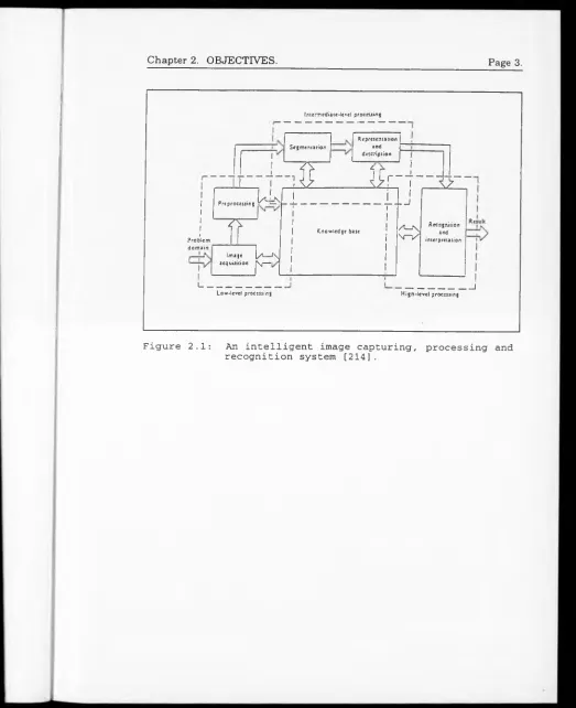
F o r a n o n -d efectiv e or p ra c tically accep tab ly defective co m p o n en t w e will
a ssu m e a n e n erg y level E th. T he im p act will induce a larg e im p u lse su ch th a t
su b s e q u e n t im p a c ts on th e sam e a re a follows a p o w er accu m u lativ e or
ex p o n e n tia l law in a context t h a t will m a k e th e re q u ire d im p a c t en erg y for the
sam e re sp o n se lo w e r locally b u t h ig h e r globally im p ly in g th e fo rm atio n of
in te rm e d ia te e n e rg y sta te s or b an d s of e n erg y in a less s ta b le e n v iro n m en t
co m p ared to th e o rig in a l s tru c tu re , hence, p ro p ag atio n of a defect is a stro n g
p o ssib ility over a m u c h longer period of tim e re la tiv e to th e im p a c t c o n ta c t tim e
(as sh o w n in F ig u re 4.1.)
F ig u re 4.1: E n erg y B a n d Model.
From th e g rap h , th r e e cases c a n be estab lish ed :
[image:51.583.13.528.13.658.2]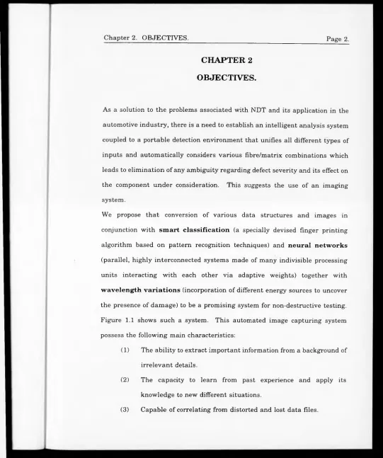
![Figure 3.1 Hybridization of composites [5],](https://thumb-us.123doks.com/thumbv2/123dok_us/9858845.487066/35.584.18.523.13.651/figure-hybridization-of-composites.webp)
![Figure 3.3: Process em ployed in the design of composites [6],](https://thumb-us.123doks.com/thumbv2/123dok_us/9858845.487066/37.581.24.527.11.658/figure-process-em-ployed-design-composites.webp)
![Figure 6.9: B-scan ultrasonic system [50].](https://thumb-us.123doks.com/thumbv2/123dok_us/9858845.487066/94.593.9.535.11.658/figure-b-scan-ultrasonic-system.webp)
![Figure 7.8: Generation of holograms using Shearography [124].](https://thumb-us.123doks.com/thumbv2/123dok_us/9858845.487066/133.585.15.532.12.665/figure-generation-of-holograms-using-shearography.webp)
![Figure 7.9: X-rays backscattering concept [137],](https://thumb-us.123doks.com/thumbv2/123dok_us/9858845.487066/136.586.16.526.14.657/figure-x-rays-backscattering-concept.webp)
![Figure 7.10: The CAT system [137].](https://thumb-us.123doks.com/thumbv2/123dok_us/9858845.487066/137.584.12.531.11.661/figure-the-cat-system.webp)
![Figure 7.11: M easurem ent of specim en reflection coefficient using Microwaves [132].](https://thumb-us.123doks.com/thumbv2/123dok_us/9858845.487066/139.583.33.527.7.660/figure-easurem-ent-specim-reflection-coefficient-using-microwaves.webp)
