Improving the Model Management Workflow
T. (Tom) Bokhove
MSc Report
C
e
Prof.dr.ir. S. Stramigioli
Dr.ir. P.C. Breedveld
Ir. E. Molenkamp
Ir. P. Weustink, Controllab Products
M. Meijer MSc, Controllab Products
Ir. M.A. Groothuis, Controllab Products
July 2016
015RAM2016
Robotics and Mechatronics
EE-Math-CS
University of Twente
Table of contents
1 Introduction 6
1.1 Goal . . . 7
1.2 Justification . . . 7
1.3 Overview of the report . . . 8
2 Literature Research 9 2.1 Model version control . . . 9
2.2 Traceability . . . 10
2.3 Provenance . . . 10
2.4 Determining an impact . . . 11
2.5 Commercial model comparison tools . . . 11
2.6 Relation to design chapter . . . 12
3 Design 13 3.1 Use-cases . . . 13
3.2 Version control . . . 16
3.2.1 Version control system options . . . 16
3.3 Desired project structure . . . 18
3.4 Combining models . . . 18
3.5 Impact . . . 20
3.6 Conclusions . . . 21
4 Implementation 22 4.1 Version control . . . 22
4.2 Metamodel development . . . 24
4.3 Conversion to the new format . . . 24
4.4 Metamodel-based model comparison . . . 26
4.5 Assigning context . . . 28
4.6 Finding operational differences in submodels . . . 28
4.7 Computing an impact score . . . 31
4.8 Graphical user interface . . . 31
5 Results 37 5.1 Failure tests . . . 37
5.1.1 Conversion from old to new format . . . 37
5.1.2 Reading in the XSD-XML tree . . . 37
5.1.3 Applying context . . . 38
5.1.4 Operational impact . . . 38
5.1.5 Failure tests overview . . . 38
5.2 Performance tests . . . 39
5.2.1 Benchmarks . . . 39
5.2.2 Timing the tool . . . 40
5.2.3 Process memory usage . . . 41
5.2.4 Performance results overview . . . 43
5.3 Accuracy . . . 43
5.3.1 Verifying differences . . . 43
6 Discussion 45
6.1 Literature research . . . 45
6.2 Design phase . . . 46
6.3 Results . . . 46
7 Conclusions and Recommendations 48 7.1 Conclusions . . . 48
7.2 Recommendations . . . 48
A Batch Scripts Version Control 50 A.1 Setting up the project structure . . . 50
A.2 Adding a new model . . . 51
A.3 Add a new version of an existing model . . . 51
A.4 Show two versions of a model . . . 52
B XSD files and Comparing Models 53 C External Tooling 55 C.1 20-sim . . . 55
C.2 TinyXml2 . . . 55
C.3 xmllint . . . 55
C.4 wxWidgets . . . 56
C.5 GIT . . . 56
D Bayesian Learning 57 D.1 Concepts . . . 57
D.2 Bayes’ formula . . . 58
D.3 Expectation-maximization . . . 58
D.4 The algorithm . . . 60
E Build Instructions 64 E.1 Project meaning . . . 64
E.2 Running the project . . . 64
Acknowledgements
During the scope of my master assignment, I got quite some help. First of all I would like to thank everyone at Controllab Products B.V. for their help, ongoing support and trust. In particular, I would like to thank Despina Davoudani as daily supervisor for the first part of my master assignment, and her help in building the initial version of the Graphical User Interface. I also would like to thank Maarten Meijer for continuing the job of daily supervisor for the second half of the master assignment, and for his help during the XML and Smalltalk aspects of my master assignment. Another thanks goes to Marcel Groothuis for his help on the software aspect of my master assignment, his advise on several software issues like the choice for a proper version control system and his council for working with Visual Studio helped a lot. Furthermore, I would like to thank Paul Weustink for his help during the impact analysis for obtaining the set of generated equations, and for his feedback. Finally, I would like to thank Christian Kleijn and Frank Groen for their ongoing feedback about respectively the user-aspects of the tool and C++ knowledge.
Abstract
Among the most recent developments in software engineering is the tendency to use a model-driven approach to give a visual representation of the system under development. One will however quickly notice that working with models takes quite some management to be effective. Every minor change might become a new version of that model, and every important version might have to be uniquely labelled to account for this. The challenges become even more complex if multiple persons are working together on the same model, since different versions of the same model exist in parallel, that eventually have to be merged again into one model.
During the research phase, it became quickly clear that version control was the way to go for managing these models. The choice was made to use an existing version control system, namely GIT. The focus for model management was placed on the tool 20-sim, a modelling tool for physical systems. 20-sim uses one file that contains all the information that the model needs to be loaded and simulated. Most of the version control actions also directly apply to this model file, like storing a commit (a version of a model) and making an alternate copy of a model (a branch), but the problem lies in merging two models, since the resulting model should be a valid model as well.
The practical phase was mainly focused on doing exactly that: analysing and categorising differences between model versions and merging these model versions together. Not just providing a textual differ-ence between two models, but really going in-depth in the context of the different aspects of this 20-sim model by using a metamodel specification of what a model should contain to be valid. By interpreting the actual components in a 20-sim model, like terms as submodel, plot, and connection, it becomes directly possible to compare these contextual components over several versions of the same model.
The unique feature of this tool, in which it goes further than any of its competitors on the market, is that it also provides a mechanism for determining the impact of a difference between two model versions, even before the merge is performed. This impact is determined based on two methods: Finding out if a set of equations has operationally changed, and trying to find an impact score for a certain difference based on what the user is likely considering a high impact difference.
Chapter 1
Introduction
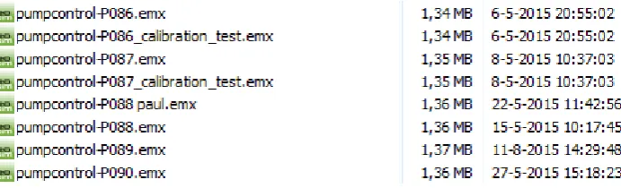
[image:7.595.126.472.404.509.2]Collaboration can be beneficial to the results of a project, but it poses challenges too. One of the fields in which little research has been done in managing collaboration is the field of computer-aided, model-driven engineering. The target of this field is to develop models as the main source of engineering with the goal to simplify the development process. Model management is a difficult issue, especially when many users work on the same model. An example of an existing project, in which a pump controller was designed, is shown in Figure 1.1. This is just part of a very long list of model versions with all kinds of version indications. The most direct version indication is the number of the model, in the figure ranging from 086 to 090. However, some models have multiple versions that are distinguished by an additional note, rather than by creating a new version. Other models indicate the version of a specific person, to indicate the author of the newly created version. Note that there was even a modification in the model with version number 089 that was modified after the last change to version 090, which can be observed by looking at the timestamps of both versions.
Figure 1.1: An example of a project in which collaboration on the same model resulted in quite some versions of a model.
The question becomes how to interpret these results from an existing project. Apparently some versions were labelled with additional information, which indicates that it is a special version of the model (”calibration test” is such an example). Sometimes there are also alternate timelines for the models, in which the project members take the same model as starting point, but both adapt it into their own version. A name then indicates whose version it is. These models are usually likely candidates to get merged at some point with the main line of models, since the project should eventually deliver a final model as product to the customer. Given all these indications on model versions, it becomes cluttered what happens in one specific version. What is for example the difference between version 089 and 090? What is the actual meaning of the label ”calibration test” to model version 086, since version 086 also exists without the label? These labels and numbers might thus be differently interpreted, and give no information about the contents of the version at hand. To summarise, the question thus is if there is a way to improve this model management workflow and increase insight in the different versions of a model.
Tests Code
Model Model
Requirements Model
Model Requirements
Code
Tests
Author: Marcel Author: Tom
Differences between versions: * Added Controller submodel * Added port for ¨position¨
signal on submodel ¨plant¨
* Changed the ¨stiffness¨ parameter of submodel ¨spring¨
Timestamp:
[image:8.595.74.481.70.245.2]12-07-2016 16:00:00
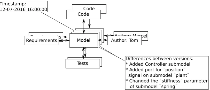
Figure 1.2: The context of a model in a project.
Requirements 1.0.1: Model Management Workflow
• There should be a means of storing the versions of a model automatically.
• It should be possible to label a specific version of a model as important.
• It should be possible to see the differences between versions.
• Versions should contain information about the time that they are created, and the person that made the version.
• It should be possible to merge versions of models that grew apart due to several users adapting the same model separate from each other.
1.1
Goal
The goal and its subgoals for this master assignment can be described as follows:
• Goal: To ease the proces of model management for a user that would like to focus on the develop-ment of models rather than the managedevelop-ment of them.
– Subgoal 1: give the user a means of easily storing and retrieving versions of a model
– Subgoal 2: give the user a means to compare two versions of the same model
– Subgoal 3: give the user a means to link his model to external factors as results, code, tests, and requirements
The first subgoal implies that the user should easily be able to indicate that something is a new version, store that new version, and later on be able to retrieve that same version. However, model management also includes some transparency. Not only does the user want a list of versions, there is also a need to see what actually happened in between these two versions. That is where subgoal 2 comes into play. The final subgoal relates to the fact that it is quite common that a model is part of a larger project. An example of such a project is shown in Figure 1.2. The first thing to note is that the project is expanded by things like requirements, tests, and generated code. The second thing is that the context of the model is also expanded by the changes made, the author of these changes, and the timestamp at which time these changes were stored.
1.2
Justification
management. The justification of this master assignment lies in using this to build an actual model management system around a commercial tool. As will become clear in the literature research chapter (section 2.5), there are not many commercial tools that apply model management or dedicated compar-ison techniques of models yet in their tool. The tool of 20-sim (2016) will be used as a starting point to try to use several scientific papers and their theories on model management in practice. Furthermore, a level of impact between model versions will be estimated that indicates how large the impact is on the simulation results of the model based on the differences between these two models. This impact analysis is something that none of the commercial tool vendors as of yet have implemented in their tool.
1.3
Overview of the report
Chapter 2
Literature Research
The introduction already shortly touched upon the problem statement of this report. The challenge lies in the management of model versions. The first useful topic is to look into version control for model-driven projects. Is there any research done on model version control, and can it give leads to finding solutions to the problem statement? The next step is to look in a concept called traceability. A model is often much more than just the model itself. Connections to requirements, generated code samples or resulting simulation plots usually are specific to a version of a model. If the model changes, these connected aspects should possibly change their behaviour too to match the new model version. Afterwards the concept of provenance is investigated, in which the topic of gathering data about a model version is the central theme. What information is crucial for identifying a specific version of a model in a large set of versions of that model? Provenance is followed by a section about impact of differences between model versions on the overall simulation results of that model. Finally, existing commercial tools will be evaluated.
2.1
Model version control
Version control is a concept that gets more and more attention lately. The development of newer and more robust Version Control Systems (VCS) makes the options for version control more applicable to different kinds of software applications too. Version control in essence is concerned with storing a version of a file, piece of code or project for later reference. The demand for model-driven version control is however also increasing, even though the development of this branch of version control seems to lack behind. Models are not just blocks of sequential code, they contain functional units interconnected with a set of connections. The main challenge here lies in identifying components of a model that can undergo an atomic operation. The unique identification of elements, the atomic model transformations, and conflict resolving are among the main problems with model based version control. These topics will each be discussed in this section.
Brosch et al. (2010) describe a framework that was developed for model-driven version control. Their model versioning system, AMOR, is a structure of steps on how to find conflicts, and resolve those conflicts in an automated manner. The conflict detection happens by comparing the new versions of the model against the original model and against each other. A set of operations is defined, which among others contains ”insert”, ”update” and ”delete” model elements. Additional operations can be defined by the user. After detecting conflicts, the system tries to find a fitting resolution strategy which can automatically resolve the conflict. If there is no such strategy, the user is asked to manually resolve the conflict. Manual resolutions are then evaluated by the system, to see if any automatic resolution strategies can be obtained from this for future conflicts. Finally, the actual merging phase is done, after which only one version will remain.
Reiter et al. (2007) describe a challenge in model-driven engineering related to the semantics of models. Changing a minor thing in a model, can have major impact on the behaviour of the model. They designed a way of versioning models that should be able to avoid this problem, by not only doing a syntactic analysis (evaluate the differences between two models), but also by doing a semantic analysis (evaluating the impact of these changes on model behaviour).
component in the model that might possibly change behaviour or implementation over time. However, if such a component is given a unique identifier, then it keeps that identifier until the end. It is then often likely that this component is completely different from its initial implementation, even though it is referred to with the same identifier. Wenzel suggests to use traceable links that link attributes, references, movements, and structurally different components, such that not the component itself, but rather its context (attributes, links, and implementation) are monitored.
Finally, one of the hints that came forward from many papers that describe model-driven revisioning is that so-called model-transformations should be monitored, rather than only the changes between revisions. In that way, one could better evaluate the difference in behaviour between models. By evaluating a step-by-step progress report of a model, one can see in-depth which components were added or removed, and which ones were changed. An example of such an article that states the importance of model transformations in model-driven version control is created by (Taentzer et al. (2014)).
To summarise, the challenges with model-driven version control lie in resolution strategies to auto-matically solve conflicts, including semantics of models in versioning, identifying components in a unique and complete manner, and using model transformations to identify actual changes to the model in a more atomic manner. Some of these challenges will be discussed in the Design chapter, as will be introduced in section 2.6.
2.2
Traceability
According to IEEE std 610.12-1990 (2002), traceability is defined as: ”The degree to which a relationship can be established between two or more products of the development process, especially products having a predecessor-successor or master-subordinate relationship to one another; for example, the degree to which the requirements and design of a given software component match.” This definition indicates the major aspect of traceability: combining software artefacts via a set of traces, such that it is possible to see what elements of a project are connected. The example of a requirement to part of a design is such an example that might be relevant for model-driven traceability. This can however be further extended to a set of tests to verify a requirement or a piece of documentation that is coupled to part of the model. Winkler and von Pilgrim (2010) made a survey about traceability in model-driven engineering, in which four phases were derived from literature: Planning and preparing, Recording, Using traces, and Maintaining. The planning and preparing phase is concerned with making a traceability scheme that identifies the elements and their relationships. The recording phase implements the traceability scheme onto the actual elements and links between those in the models. Using the traces means that data can be taken from those traces that might be used for generating documentation, finding relevant information about the connection between models and their elements, and maintaining model consistency. Once everything is in place, it should also be maintained. If elements are added, deleted, changed or duplicated, this means that their corresponding traces also change. This is the primary goal of the maintenance phase. Schwarz et al. (2010) suggest additional phases like identification (using automatically found rela-tionships to derive additional relarela-tionships) and retrieval (getting the trace information back), however these can be placed within the four phases defined above. Schwarz a.o. did however make an additional distinction in intra-level traceability (traceability at one level of a software architecture) versus inter-level traceability (traceability that ranges over multiple levels of a software architecture).
Hull et al. (2005) describe in their book a chapter about traceability, in which they also define some benchmarks to traceability over multiple levels of a software architecture. The first is breadth: to what extent are the requirements in the architectural level above covered by the current layer of requirements? The second is depth: how deep are the requirements propagating in the model (i.e. in what sublevel of a software architecture is the requirement needed)? The final one is growth: what is the impact of a change of a requirement to the other requirements throughout the system?
2.3
Provenance
corresponding to software artefacts, rather than the storage of the software artefact itself. Provenance is also very applicable to several domains, like scientific workflows, databases, security, and bioinformatics. Cheney et al. (2008) provide some challenges that were discussed during their provenance workshop. Their first concern is that the direct benefit of provenance is not directly clear. This also will make it unlikely that users maintain the provenance tags to their software artefacts on the long term. Another challenge is to determine what to track and who to allow to use these tracking tags for data. This latter option of who is allowed to watch the provenance data, is often used in security applications that make use of provenance. In model-driven design and architectures specifically, the maintenance of model transformations, as well as the propagation of changes in models were once more mentioned as important aspects, also for provenance (these were introduced in section 2.1).
Provenance is described by Shamdasani et al. (2014) in three aspects: tracking changes to provide historical records of actions performed, the outcomes achieved, and design decisions taken. They use an XML scheme to couple this additional data to a model. The main usage for their application of CRISTAL is event-driven and state-based. Their main focus is on workflows (which are directed graphs, with states and events). There is a lot of provenance data stored for each state for each revision: event ID, activity name, previous and target state, transition, outcome scheme name and version, agent name, agent role, and time stamp. An agent is defined as a human user or automated system that operates on the model.
Another approach towards provenance is a more formal one by Dezani-Ciancaglini et al. (2012). Their approach is to formalise the mathematics behind provenance in a triple based on linked data management. This triple consists out of the following elements: subject, property, and object. The subject is the place or repository in which to look for data, the property is the type of search that is done, and the object is the search term. For example: Look for data in the subject ”University library” on property ”year of publication” and object ”2012”.
Besides their formal algebra, Dezani-Ciancaglini et al. (2012) also define types of provenance: ”where now provenance” (next to their triple of data, a location is added of where the data is currently located), ”who now provenance” (next to their triple of data, an agent that published this data is added), and ”how provenance” (recording the operations applied to the triple of data).
2.4
Determining an impact
In model management, the impact of the differences between two model versions is an important indicator in seeing how relevant a certain change is. Therefore, as an additional feature to the model comparison tool, some investigation was done in two types of impact. The first one was already mentioned by Reiter et al. (2007), and is detecting not only that a difference occurs in the equations of a submodel, but also keeping into accounts the semantics of the model. In that way, it becomes possible to see if there is an actual operational difference, that might also affect other parts of the model that are connected to that submodel. The design chapter will couple this part of the impact to the rest of the master assignment (section 2.6).
Furthermore, a technique called Bayesian learning will be used to estimate a percentage of impact. Bayesian learning is a technique taken from the domain of artificial intelligence, and it computes the probability that a certain impact score is what the user wants to see, based on a set of learning examples that include information about the component of the model that changed. This set of learning examples can be expanded by learning examples that the user chooses to include. This means that the impact scores that are given, will be biased by the wishes of the user. More information about this Bayesian Learning technique is shown in Appendix D, which is based on the articles of Yang (1997), Do and Batzoglou (2008) and Osoba et al. (2011).
2.5
Commercial model comparison tools
There are quite some theoretical tool ideas available for model comparison according to modeling-languages.com (2010), but there are only few actual commercial applications that use model-driven version control. This master assignment was not done to add another theoretical tool to this list, but to see if it is possible to use this research and apply it to an actual commercial tool.
they do not provide the model context to the user, but simply perform an XML-comparison. They do not show the submodels, ports or connections that changed, but rather a set of XML tags that changed between two model versions. There are a few examples of such commercial model merging tools, however they are sporadic and mostly focussed on the program Simulink. Mathworks does have their own tool that can show the XML differences between the .mdl files that are created in Simulink, but also does not provide context. A more commercial tool is SimDiff (made by EnSoft Corporation (2005)), another Simulink model comparison tool. This tool however does provide a layer of context by indicating the submodels in which a difference occurred, and by providing a mechanism for merging simulink submodels. It is possible to either merge two models into a new Simulink model or merge another model into the currently opened model. Furthermore, SimDiff has the possibility of showing differences at a graphical level by a colour indication of the changed submodels.
2.6
Relation to design chapter
The literature gave some interesting leads for the rest of this assignment. One of the main topics in model-driven version control was to include semantics in merged models. Does the simulation result of the model change due to the differences found between both versions of the model? This directly couples to traceability. For example, if a submodel changes, then the set of traces to for example corresponding unit tests can become outdated. One step further down the road, it might even be possible to regenerate these results based on invalidating outdated traces to this specific submodel. Shamdasani et al. (2014) go on with provenance that it is not only historical tracking of data, but also monitoring the outcomes. Combining these three topics, one could see one main line of reasoning: A model is not only the model file, but it is the full combination of the model, its requirements, tests, documentation and its results. In the ideal case, one would thus not only merge the model, but also regenerate the results of that model if the semantics of the model change. An initial proof of concept of this phenomenon is described in the Impact part of this chapter in section 3.5.
Another part is the impact aspect. A technique from the artificial intelligence field is used to make an estimation of an impact score of a changed submodel. This estimation will be based on several properties of a submodel, like the fact that a port was added or deleted or the fact that the submodel operationally changed its behaviour. This part will be treated in the Impact part of this chapter in section 3.5.
Chapter 3
Design
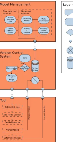
Model management is quite a broad concept. This chapter will introduce which parts of model manage-ment are going to be covered in the rest of this report. The main idea is to develop the tool support needed to use a regular version control system for model-driven version control. As an extension to regular version control systems, an additional impact analysis will be performed, that evaluates the dif-ferences and tries to find the impact on the simulation results of the model. An overview flowchart is shown in Figure 3.1.
This overview diagram will be the basics of the rest of this chapter. section 3.1 will go into more details about the use-case scenarios mentioned in the Model Management block of the figure. The version control section is described in section 3.2. In this section an evaluation is done on the most promising existing version control system to be used in model version control. Furthermore, this section explains a technique called subtree merging, needed for proper model-based revision control at model level. The block ”Version Control System” in the figure shows a basic flowchart of the version control, in which all use-cases first relate to the version storage database, and afterwards the decision is taken to call the Tool block or not. The Tool block itself in the figure represents the Tool designed during this master assignment. The blocks ”Obtain XML tree”, ”Add Model Context”, ”Find Differences”, and ”Merge Models” are described in section 3.4. The block ”Determine Impact” is further elaborated on in section 3.5. For the implementation chapter (chapter 4), the tool 20-sim will be used as modelling tool for implementing this flowchart. For more information about the tool 20-sim, see Appendix C.
Before continuing with the rest of this chapter, the text above will be formalised in a set of require-ments, that are the core reason to write the rest of this chapter. These requirements are added to the already presented list of requirements given in chapter 1 in requirements block chapter 1.1.
Requirements 3.0.1: Design
• Where possible, the model-driven version control should make use of existing functionality al-ready available in file-based version control systems.
• It should be possible to keep track of the history of every separate model, and also of the folder containing the models.
• Based on increasing the effectiveness of model management, the graphical user interface should include ways of giving users feedback on the impact that differences between model versions might have.
• The implementation will be done in 20-sim, which means that a dialogue has to be made that handles the basic interaction with 20-sim in an intuitive manner.
3.1
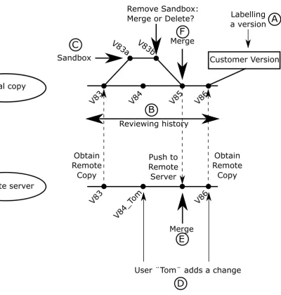
Use-cases
V83
V84
V85
V86
Customer Version
Reviewing history
Labelling
a version
V83a V83b
Sandbox
Merge
Remove Sandbox:
Merge or Delete?
Local copy
Remote server
V83
Obtain
Remote
Copy
Push to
Remote
Server
V84_
Tom
User ¨Tom¨ adds a change
Merge
V86
Obtain
Remote
Copy
A
B
C
[image:16.595.122.523.64.485.2]D
E
F
Figure 3.2: A graphical representation of the use-cases.
to create a new version, and where to obtain requested versions from. The results of this monitoring can be used in various cases, like reviewing the history of a model or merging models together.
Add/Open/Save/Save As The four basic actions for creating opening and storing models are accessible to users. The main idea behind this use-case, is that the user should be able to press these buttons without having the feeling that under the hood they are doing revision control. On the other hand, the user should get access to the features that are related to version control, like reviewing the history, which needs monitoring of when the user presses these buttons.
Label a special version It should be possible to label certain projects or models via a tag. For example, a tag could be ”Final version”, ”V1.0”, or ”customer version”. By using these labels, it should become easier to retrieve that exact model or project revision later on. A dialogue with a history line for all versions could for example contain a list with all these special labels, such that upon clicking on a specific label it will automatically go to that point in time. Figure 3.2 for example shows in the local copy that V86 is labelled with the tag ”Customer Version”, as indicated by the letter A.
back and forth through time to visit older versions of a model and compare them with newer versions of that same model.
Making a sandbox of a model A sandbox is meant for quickly trying something out in a model. A simple example is a basic control loop. At some point, it might be useful to evaluate a different type of controller. The current approach is to either make a copy of the model and store it under a different name or add the controller as another implementation to the already existing controller. A sandbox makes a temporary copy of a model, in which it is possible to add the new controller. The simulation results can then be evaluated, and a decision can be made about deleting all changes in the sandbox or merging them with the original model. In that way there is no need to change the original model with possibly failing submodels, until they have proven themselves to be useful. Figure 3.2 shows one possibility of a sandbox, indicated by the letter C. The local version V83 splits up into a version V83a. Version V83a is an adaptation of V83, and V83b is an adaptation of version V83a. At some point, the sandbox version V83b is ready, and the user decides to merge back the version V83b with the then applicable version V85. A merge is needed to combine the new behaviour of the sandbox, with the main line of history of the local copy.
Model collaboration For user collaboration, it should be possible to identify a shared location as shared project. When a user has a network connection, these changes can then be placed in a queue on the shared location. Once the user sees his changes as useful to share with others, it is possible to merge all or a set of his changes with the overall shared project. In this way, easy collaboration can be achieved within projects that have more than one person working on the same model. Figure 3.2 shows several points of remote to local or local to remote connections. These are indicated by dashed arrows between the timeline of the local copy and the timeline of the remote server. Note that it is possible that another user, in this case user Tom (indicated by the letter D in the figure), alters the history on the server. This means that a merge of Tom his version and the user its version should be merged to obtain the next server version (indicated by the letter E). Another more local merge is shown in the same figure by the letter F.
Checking model differencesBesides all kinds of version control related use-cases, it might also be convenient to use the tool for regular usage in 20-sim. It is often insightful to have two models, and just view the differences between these two models or merge these two models into one model. There should be a dialogue that shows this result in 20-sim in a proper and intuitive manner.
3.2
Version control
Version control lies at the basics of file management, but it is also a crucial part of model management. Instead of putting tens of versions in one folder (for example, see Figure 1.1), to which everyone can make changes at any time, it becomes possible to check out one model. This makes sure that you work on one version at a time, and the version control system will make sure that merge conflicts due to collaboration on the same model will be properly resolved (most likely with user interaction). This merge seems to be the main problem though, since model merging is different from file-based merging. Brosch et al. (2010) and Taentzer et al. (2014) were already mentioning the difficulties with comparison of models for the use of version control, in the sense that model transformations have to be monitored, and merge conflicts often have to resolved by relying on model-based merging algorithms. On the other hand, all the other functionality of the version control system is almost identical for both file-based and model-based versioning. ”Committing” a new version of a file or a model is exactly the same. Opening a specific version of a model or file is also identical. Even remote sharing of models is the same as files, provided that a proper merging tool exists. Therefore it does not pay off to write a fully new version control system for model-driven version control, if most of the functionality is already available for models too. The section below will therefore evaluate existing version control systems, and see which one matches the needs of model-driven version control the best.
3.2.1
Version control system options
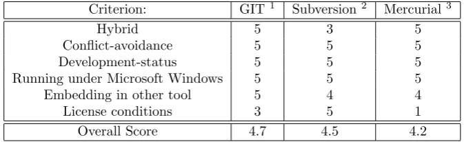
Criterion: GIT1 Subversion2 Mercurial3
Hybrid 5 3 5
Conflict-avoidance 5 5 5
Development-status 5 5 5
Running under Microsoft Windows 5 5 5
Embedding in other tool 5 4 4
License conditions 3 5 1
[image:18.595.129.466.71.174.2]Overall Score 4.7 4.5 4.2
Table 3.1: The Design Space Exploration for the Version Control software.
possible score, and 5 being the best possible score. The overall score is the average of the score in the rows above, and is the final score on which the version control system will be chosen.
First of all, the version control system should work under Windows, because it should cooperate with the tool 20-sim that only runs under Windows. This requirement is satisfied by all three version control systems. Furthermore, the version control programs should be able to be embedded within the application analysed in this master assignment. Also this embedding in another tool goes fine for all three version control systems. Git has a library version called libgit 2. This set of libraries is fully written in C++, and thus can be easily embedded with the C++ code for this application. C++ is not necessarily a requirement for the tool, however it is a language that supports decent object-oriented programming, which is useful for the tools to be developed in the Implementation chapter. Furthermore, C++ is a language for which the most experience is present in the company at which I do my master assignment. Subversion is already written in C, and thus can also be used in existing C++ applications. Mercurial is completely written in Python, which works easily together with C++ too. The only reason to give GIT a 5, and the other systems a 4, is that GIT directly works with C++, without having to do a conversion from another language.
License conditions are a criterion for commercial tools as well. GPL, the General Public License, is a license that states that any tool that includes this piece of code in their application should also make their own source code of their software publically available. Mercurial falls under this license, and thus gets a score of a 1. GIT falls under the GPL license too. However, libgit2 does not. Libgit 2 falls under the GPL license with an extension for linking the source code. Thus as long as the source code is not altered and just compiled along with the source code of the application developed, then the source code of this latter application can remain private. The Apache license, under which SubVersion falls, is the best license condition for commercial software, since it puts no restrictions on putting own source code online when linking against programs falling under this license.
The development status of the version control systems is important, since if there has been no recent development on the tool, it is likely that this tool might not get any bug fixes or new updates anymore. At the moment of writing (12 June 2016), the latest version of Mercurial, 3.8.3, was published on the first of June 2016. On 28 April 2016, version 1.9.4 of Subversion was published. For GIT, version 2.8.4 was the last released version control system. It was released at the seventh of June 2016. These are all quite recent, and thus deserve the maximum score for this point.
Avoiding conflicts is mainly done by using clever merge strategies that can do some things already automatic. One feature that might aid to this goal is using external merge tools that are especially made for the purpose of avoiding conflicts. All three version control systems do have the possibility to plug in external merge tools, which means that for avoiding conflicts there are not many problems.
Hybrid behaviour of version control systems means that they are a combination of a centralised and a distributed approach for version control. A centralised approach for version control means that one central remote server is made, and committing new versions for storage can only be sent directly to this shared remote server. A distributed version control systems means that there is no shared server. All development is done locally on several computers indepedently. Working together is achieved by sending each other so-called patches. A patch is a set of changes that can be applied to a certain version of a model to upgrade it with the new features of the patch. The ultimate version control system for model-driven version control would be a combination of both: having one remote server that collects the overall work, while still being able to do some version storage locally and without network on a separate
computer. GIT is officially distributed, but does have quite some support for remote access. GIT also has built-in functionality, like ” git push”, ”git pull”, and ”git fetch”, that are specifically introduced to do communication with remove repositories. SVN is purely centralised. Another version control system, SVK, expands SVN with distributed features. Unfortunately, the status of development is discontinued for SVK. Mercurial on the other hand is quite distributed, but does have built-in support for remote servers just like GIT.
3.3
Desired project structure
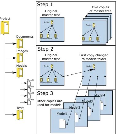
One model itself under version control is not a problem. It becomes more difficult once this model is part of a larger directory structure. For this section, the assumption will be made that there is a project under which a folder with the name Models is created that stores all models related to that specific project. The left part of Figure 3.3 shows an example of such a project structure, in which the Models folder is collapsed. The following demands were made for this project structure:
• The projects folder contains a folder that stores all models (as can be seen in the left part of Figure 3.3).
• To avoid intertwined history, the projects folder, models folder and all models themselves should maintain their own history. Each model should maintain history about operations that only concern that model. The models folder should maintain history about operations that involve multiple models at the same time. Finally, the projects folder is for maintaining general project operations in history.
• GIT can only perform updates on a complete tree at once. This means that to only update one model at a time, the model should get its own tree.
GIT has no direct way of providing this functionality of switching only one model or switching only one folder under another folder. There is however a technique in GIT called subtree merging (chapter 7.8 of (Chacon and Straub (2014))). Subtree merging allows to create an alternative file tree next to the project root tree, which then can be hung under a folder of the original tree. The right part of Figure 3.3 shows a three-step approach of performing this subtree merging action in GIT. The first step is creating an initial project structure, in which a Project folder and the underlying Documents, Images, and Tests folders are created. By making five copies of this ”master tree”, alternate histories can be created for these trees from that point on. The trees can also be seperately altered. Step 2 does exactly this and alters one of the copies to contain the Models folder. Subtree merging is now exactly that: merge a tree (in this case the Models folder tree) to a subtree of another tree (in this case the Project folder tree). The final step is to alter the other four copies into trees that only have one single model. These model trees should be hung under the Models folder tree. This is done via subtree merging again.
At this point, it becomes possible to update only a single model, since it has its own tree. Any GIT action that would regularly be performed on the top-level tree, can now also be performed on these subtrees (adding models to be monitored, sending a new version, and so on). Switching between trees can be done via the usual git checkout command.
3.4
Combining models
As was discussed in the literature research chapter (chapter 2), model transformations often lie at the base of combining models. The differences between two versions of a model can be described as the set of atomic actions applied to the first model to get the second model out of it. Unfortunately, 20-sim does not support model transformations. There is no such thing as atomic actions that are tracked by the software in 20-sim. For that reason, these atomic actions have to be recreated based solely on the two versions of the model. To do so, it is crucial to have a basic layout that each 20-sim model should fulfil. In that way, basic components from 20-sim can be identified that mean something to the user, and that could be interpreted as atomic actions between the two versions of the model.
Project
Documents
Images
Models
Tests
Model1
Model2
Model3
Model4
Project
Documents Images Tests
Project
Documents Images Tests
Project
Documents Images Tests
Project
Documents Images Tests
Project
Documents Images Tests
Project
Documents Images Tests
Original master tree
Five copies of master tree
Project
Documents Images Tests
Original master tree
Models
First copy changed to Models folder
Step 1
Step 2
Step 3
Model4Model3
Model2
[image:20.595.109.491.68.503.2]Model1 Other copies are used for models.
Figure 3.3: The project structure tree from the Project root folder to a Models folder with separate models under-neath (left), and the approach in GIT to recreate this tree via branches (right).
Schema Design (XSD) files and Document Type Definition (DTD) files. The first one is written in XML, and thus easier to learn for someone already working in the XML language. The latter has its own syntax, and thus needs a steeper learning curve to write XML specifications in. On the other hand, DTD files are used as specification for more than only XML files (SGML, HTML, and so on). The choice for the XSD formalism was made based on the first argument about the XSD being written in XML too, in combination with the fact that Controllab Products B.V., the company at which this assignment is done, has already prior experience with XSD’s. This prior experience could help in pinning down issues that arise upon using the XSD formalism.
of a model. This can either be done by forcing the code that generates these tags to give an indication that a certain impossible combination has been created or by neglecting tags that are present, but that do not contribute to the model behaviour. The prior option has the advantage, since unneeded tags should not be present in the model XML where possible.
The next step would be to merge these two initial versions of the model, which usually also goes via these model transformations. The set of atomic operations is still defined as the exact difference between model version 1 and model version 2. To merge these two models, take the first version and apply the atomic operations corresponding to the desired features from model version 2. As was discussed, atomic operations are not supported in 20-sim. However, it is possible to obtain that part of the 20-sim XML that corresponds to a certain user-intuitive 20-sim component like ”Submodel” or ”Plot”. It then becomes possible to compare both versions of the model just like model transformations usually would do. In section 2.6, the set of basic actions for model transformations were already mentioned as being insertion, deletion, and modification. These three actions can still be applied to the difference and merge system described in this section. It can be checked if a component is present in one but not in the other version (insertion or deletion), and it can be checked if there is a difference between a component that is present in both versions.
It is not too difficult to combine two XML files, it becomes difficult however if the resulting XML file should also fulfil the specification of a 20-sim model that can be processed and simulated. This is however exactly what is needed for this step of combining two models. Even though the XSD might not always be as complete as would be ideal, it still contains a complete set of all XML tags that could be present in the model XML. If the tag is not in the XSD, it can never be present in the XML. The idea here is thus to start off with building a tool that reads the xsd, and assigns the corresponding xml tags along the way. Eventually, two such ”XSD trees” will be made (for each of the two models one tree), which then can be compared and checked for differences. This will be further elaborated in section 4.4, including a picture on how this is done in the application designed in this master assignment.
The next step in combining these two models is to use this newly gained data structure, and obtain components that mean something to the modelling tool. Things like connections, plot objects or sub-models are much more intuitive to the 20-sim user, than random tags from an XML file. Therefore the xml tree will be cut into pieces and assigned to the specific type of object that is to be tested. In that way, the list of differences will not be XML tags, but actual components that mean something to the user. In section 4.5, more information about assigning context is given, including a picture that shows which contextual blocks were taken for the proof of concept and how they relate to each other.
Finally, the user should be made aware of the differences between both versions of the model. The extracted 20-sim components (submodel, plot, etc.) taken from both XML representations of the 20-sim models should be used to show the insertion, deletion, and modification in a graphical manner.
3.5
Impact
A difference tool for 20-sim is one interesting feature to add. However, the functionality that such a tool can offer can be much more than just viewing differences and merging models. During this master assignment, part of the time was focussed to look at the impact that these differences had, mainly on the simulation results of a 20-sim model. This section will discuss exactly that: strategies for finding the impact of differences between versions of a model.
component, in this case a submodel. section 4.6 will go more into details on how this was implemented in the first proof of concept.
Another aspect of impact, is that a list of differences is just a plain, unsorted list of differences. The question is which difference should get priority for attention of the user? The user does not always want to go through all minor differences trying to find the perfect merge, but sometimes likes to do a quick merge of all major differences. In that case, a notion of a major difference should be defined, according to the user its wishes. A first estimate is that the user wants to see those differences that impact the simulation results the most. By using artificial intelligence, it becomes possible to generate a set of learning examples that focusses on impact on these simulation results. Another advantage of using an approach from the field of artificial intelligence, is that the user can add his own learning examples if he does not agree with what differences are labelled to be major. The technique used in this report is based on Bayesian learning, which is explained in more depth in Appendix D. The idea of Bayesian learning is that, based on a set of statements that can be either true or false, an estimation can be given of this impact score. Thus for a submodel, some statements could be: Submodel has been operationally modified, submodel has many ports, and submodel has newly added implementations. Given these statements, and what the impact score was for previous learning examples with specific combinations of true and false for these statements, it becomes possible to do an estimation of which difference is the most relevant to the user. The algorithm to do this, is also explained in Appendix D.
3.6
Conclusions
Chapter 4
Implementation
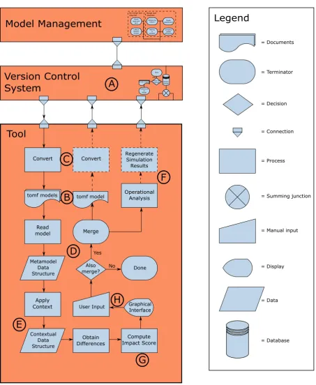
This chapter presents the complete overview of the implementation of the tool. It will start off with the initial design of the version control system in section 4.1. The other sections are all about the main application of this master assignment: the comparison tool. The flowchart shown in the Design chapter in Figure 3.1 has been adapted to include the actual flow of the comparison tool, as shown in Figure 4.1. Note that the Model Management and Version Control System blocks are minimised, to give more space for the Tool block. This figure will be the base for the rest of this chapter, because it will be used to place each section in the context of the comparison tool or the overall picture of model management.
4.1
Version control
Version control lies at the base of model management. It is therefore the starting point of the flowchart of the comparison tool. In fact, version control will call the comparison tool for differences (and a merge) when needed. Version control is indicated by the letter A in Figure 4.1. An initial attempt was made to use version control to make a project structure that adheres to the specification given in Figure 3.3. The technique used for this is called subtree merging. Subtree merging works with creating additional so-called branches of a model. A branch is a way of creating an alternate timeline in GIT. Branches are common in GIT for trying something out, and merging the results back to the original master branch. Effectively however, a branch is nothing more than a tree.
For subtree merging, the main master branch is corresponding to the top-level Project folder in Figure 3.3. For the Models folder, an empty branch is created, which is in fact a copy of the Projects master branch that is emptied afterwards. This now empty tree can be used to add a Models folder, and later on the models underneath. Subtree merging is the technique to connect this tree under the project folder in the original master branch. For the separate models in the Models folder, the same thing applies. Each model gets a separate empty branch to which the specific model is added. These model branches are added under the Models folder branch. At this point, the tree structure in Figure 3.3 has been recreated.
Branches have their own history, such that this history is available at project level, Models folder level, and at separate model level. Switching in between these levels in the project structure can be done via the usual command for switching between branches, namely the checkout command of GIT. Furthermore, the general commands of GIT can be used to do the basic version control operations of file-based version control on models. For example, the commands ”git add” and ”git commit” can still be used to respectively label a file to be monitored in the version control system and storing a version of the changed files that should be monitored by the version control system.
Version Control
System
Differenceor Merge 20-sim models Version
Storage Merge tool required? Done else
Model Management
Modelopen and save Reviewing history Making a sandbox Label a specific version Model collaboration Checking model differences No merge tool
required. Merge tool required.
Convert
Read
model Merge
Convert RegenerateSimulation
Results
Tool
tomf models OperationalAnalysis
Apply Context Compute Impact Score Metamodel Data Structure = Documents = Terminator = Decision = Connection = Process Contextual Data Structure Obtain Differences Graphical Interface User Input Also
merge? No Done Yes
tomf model = Summing junction
= Manual input
[image:24.595.72.526.119.672.2]= Display = Data
Legend
= DatabaseB
A
C
D
E
F
G
H
manage the versions of a model and to show several versions of a model next to each other are discussed in Appendix A in more detail.
4.2
Metamodel development
Before starting with the actual tool, the decision was made to create a new model-format for 20-sim. The original model-format of 20-sim is the so-called Expanded Model Xml (EMX) model format. This model format is one single file that is half XML, and half plain text. The XML part of this format describes the plotting section of 20-sim, and a lot of toolboxes. The textual part contains information about anything related to the 20-sim canvas in which the actual model is built. Both parts give essential information about differences between two versions of a model, however plain text is very difficult to interpret. It becomes even more difficult because of the fact that part of that plain text is written by the user. The text as the user types it in 20-sim equation models, is inserted in this plain text. The user is in that sense completely free to add as much tabs or spaces as the user desires, and one equation could be spread accross multiple lines. All these challenges with plain text in the model file were the first reason to design a new format for 20-sim. The new format should be completely in XML, such that it is easy to interpret. To do so, the existing knowledge that was already present in 20-sim, was used to write the full information about the canvas to XML format.
Another reason to design a new format for 20-sim, was the fact that the format was frequently expanded over time when new features of 20-sim were added for storage to this format. This growth of the format had the consequence that due to reasons of backward-compatibility with older versions of 20-sim, new information often was stored at positions that did not make sense from a tool perspective. One such an example is the relation between plotting windows and the plots they contain. One plotting window can contain multiple plots in 20-sim. These are however stored in the EMX format as completely separate tags, linked via a set of plot IDs. What would make more sense is to store the plots as actual childs of the plotting window they are part of.
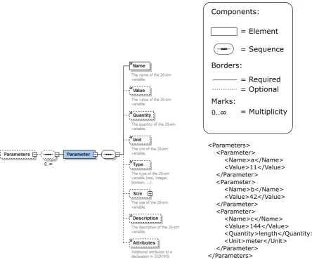
The two design criteria mentioned above, about the conversion from plain text to XML and the more logical ordering of 20-sim components, resulted in a new format called the 20-sim Open Model Format (tomf). The new format is shown in Figure 4.1 at the letter B. The idea behind this new format is that it consists out of three things: the model file, a metamodel file, and a set of implicit rules. 20-sim has default values for almost anything. Take for example the Euler integration method with step size of 0.01 seconds. This is the default choice in 20-sim to perform a simulation with. If a user would not change this, then it is not relevant to store this in the model file, since it is default behaviour. It starts to become relevant to store once the stepsize or integration method is changed by the user to another integration method. On the other hand, there should be something that does know this value. How does 20-sim know the default behaviour, if it is nowhere written down? This is where the second part of the new format comes into play: the metamodel file. The metamodel stores what the default behaviour is of 20-sim, what information is stored at what position in the model file, and how many times information can occur. An example of the latter criterion is for example that it is possible to have 20 plots in a plotting window in 20-sim, but a plot can only have one type, like a graphplot or a 3D animation plot. Finally, the set of implicit rules indicates model behaviour that cannot be captured in the metamodel. These rules usually are if-then relations. An example of such a rule is the fact that if a variable has the quantity ”current”, then its unit cannot be ”metres”.
The metamodel used in this report, as was described in section 3.4, is called an XML Schema Design (XSD). To get an idea on how this works, an example was made for the case of Parameters. This example is shown in Figure 4.2. Basically, there are two components here: an element and a sequence. An element in the XSD directly maps to a tag in the XML, and a sequence shows that the elements (or tags) underneath it should occur in that order in the XML. The multiplicity indicates that under the Parameters tag in the XML there can be any number of Parameter tags. Furthermore, every Parameter tag needs a Name underneath it, but all the other tags are optional. The right part shows a piece of XML that satisfies this schema. For more information about the supported constructs of this XSD format in the comparison tool, take a look at Appendix B.
4.3
Conversion to the new format
<Parameters> <Parameter>
<Name>a</Name> <Value>11</Value> </Parameter>
<Parameter>
<Name>b</Name> <Value>42</Value> </Parameter>
<Parameter>
<Name>c</Name> <Value>144</Value>
<Quantity>length</Quantity> <Unit>meter</Unit>
</Parameter> </Parameters>
= Element
= Sequence
= Required = Optional Components:
Borders:
Marks:
[image:26.595.75.520.69.439.2]0..∞ = Multiplicity
Figure 4.2: On the left a visual representation of part of the XSD model, made in Altova XMLSpy 2016 Profes-sional XML Editor. On the right a piece of XML that satisfies this XSD model.
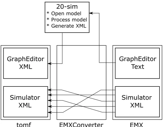
from any EMX model to the new tomf format, as shown by the letter C in Figure 4.1. The conversion process itself is shown in Figure 4.3. Note that the EMXConverter is the C++ application written for the sole purpose of converting from the EMX format to the tomf format. There are two parts of the EMX format that have to be converted to the new format: the grapheditor and the simulator. The grapheditor contains information about the submodels, their connections, their parameters and their equations. The simulator contains all information about performing simulations, including the plots, toolboxes and integration method information. As can be observed from Figure 4.3, the simulator part of the EMX format is already in XML. This conversion can be done straightforwardly by rearranging the tags in the XML such that they fit the new metamodel format. This conversion is performed by using the XML-parser TinyXml-2 (see Appendix C for more information about TinyXml-2). This parser first creates a tree from the XML part of the EMX format, and then creates a new tree in which it places the tags in the proper order and with the proper name for the new format.
tomf EMXConverter EMX Simulator
XML Simulator XML
GraphEditor Text GraphEditor
XML
20-sim
[image:27.595.161.436.69.282.2]* Open model * Process model * Generate XML
Figure 4.3: The conversion process between the old and the new format.
4.4
Metamodel-based model comparison
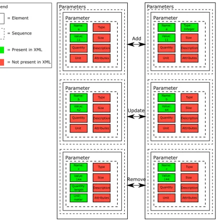
Given the fact that an EMX model is now in the new format, the next step is to read in this new format in such a way that it can be compared to other models in the new format. To do so, the metamodel of section 4.2 is used to make a tree that contains all information that is needed for 20-sim to open, process and simulate a 20-sim model. Take Figure 4.2 as an example. The XML has the information about three parameters, their names, their values, and for the last parameter also the quantity and unit. The metamodel knows that there can be other optional tags like Description, Size and Type. It also knows that the default value for a parameter is that it has no description, a size of 1 by 1 (scalar), and that the type is by default a real number. To include all this information of both the XSD and the XML, a tree is made in a C++ application that runs through the entire XSD metamodel. For the specific part of the XSD corresponding to the parameter example in Figure 4.2, this process has been worked out in Figure 4.4. Every block (both dashed and solid lines, except for the legend) is an actual instance of a class made in C++. These instances are either of the class Element (solid lines) representing a tag in the XML or off the type Sequence (dashed lines), forcing its child elements to be in that exact order in the XML. The left side of this figure shows exactly the Parameters example of Figure 4.2. The tag highest in the hierarchy is the Parameters tag. Underneath, there are three sequences that each contain a Parameter tag and inside this Parameter tag another sequence. Underneath this sequence, there are the actual properties of the parameter. On the left side of the figure, these are the parameters a, b, and c with respectively the values 11, 42 and 144. The right side of the figure shows another version of this model, in which the parameters a, b and c are adapted. Parameter a now is an integer number, parameter b has another value and parameter c has no more a quantity and unit.
Parameters Parameter Name: a Value: 11 Quantity Unit Type Size Description Attributes Parameter Name: b Value: 42 Quantity Unit Type Size Description Attributes Parameter Name: c Value: 144 Quantity: length Unit: meter Type Size Description Attributes Parameters Parameter Name: a Value: 11 Quantity Unit Type: Integer Size Description Attributes Parameter Name: b Value: 44 Quantity Unit Type Size Description Attributes Parameter Name: c Value: 144 Quantity Unit Type Size Description Attributes Update Add Remove = Element = Sequence
= Present in XML
[image:28.595.92.526.67.510.2]= Not present in XML Legend
Figure 4.4: Reading in the XSD tree, based on Figure 4.2 (left) and comparing with a slightly modified version (right).
c its quantity and unit. Figure 4.4 also indicates these differences with three types: add, update and delete. The same model transformation types were mentioned by Taentzer et al. (2014) and Brosch et al. (2010).
4.5
Assigning context
The previous sections were just working with XML tags. These tags are not very easy to interpret by users. Therefore, an additional layer of context was developed. This context should provide a wrapper around the XML, such that the differences between the models should be in intuitive concepts like a plot or submodel. The flowchart of Figure 4.1 shows this step in the process of comparing two models with the letter E. The set of currently supported context blocks is shown in Figure 4.5. Note that all classes in this diagram share a common parent class that defines the set of minimal functions to implement for each context class. This parent class is called the Block class. It forces each child class to have at least the following functionality:
1. A function that writes the XML tree corresponding to the current contextual block to file.
2. A function that compares two blocks and checks if they are equal to each other.
3. A function that gathers a list of all differences between two block instances.
Besides this functionality, there is still a function planned to be added that will be able to write user-intuitive messages to a user interface about what the actual differences are. One can imagine that only seeing that a curve in a plot has changed is useless without knowing the details about what has changed to the curve. An example of such a message can be: ”The curve changed colour from blue to green”.
The Block class childs in Figure 4.5 start out with a Model on top. This Model is split in a GraphEd-itor part and a Simulator part. The GraphEdGraphEd-itor represents the root model in the 20-sim canvas, and thus can have any amount of implementations, represented by the Implementation class. Implementa-tions can have any number of interface ports and interface parameters, and can be either graphical or equational. Furthermore, equational models can contain parameters, and graphical models can contain again a set of submodels, connected by connections. On the Simulator side there are parameters that can be changed in the simulator. These are parameters that are already defined in the grapheditor part, but for example changed unit in the simulator for plotting purposes (the plot should be in miles, but the computations were done in kilometres in the model). Furthermore, the simulator contains user-settings for various dialogues (including the simulation method and step size) and toolboxes, and it contains plotting windows called plotpanels, followed by the plots that are stored within them. These plots can be of various types, but the objects they represent are either curves or 3D objects. The division described above suggests that it is currently only possible to show differences at context block level, since other properties that are not given their own Block class are still only present in the XSD-XML tree. Some of this problem is solved by displaying additional information in the graphical user interface, as will be discussed in that section (section 4.8).
A challenge that arises with these contextual blocks is how to handle things like timestamps. There is almost always a difference in timestamp, but this is not a difference that should pop-up in the comparison of two models. There are many more of these types of differences that are actually not relevant to account for. The tool supports filters that are specific to the context class, that filter out any tag that should not be compared for upon looking for differences in that specific context class.
4.6
Finding operational differences in submodels
At this point, differences can be found between two model versions. However, currently every difference is the same, from a difference in font type of the label of a curve in a plot to the fact that there might be actual equational changes in a submodel. The latter is much more relevant to see for a user, since it actually changes the behaviour of the simulation. The tool however does not have this notion of relevance yet. This section will describe a first approach on finding submodels that have been operationally changed, because their equations do not represent the same input-output relations anymore. The step of operationally finding differences is part of the flowchart in Figure 4.1, and is shown by the letter F.
Model GraphEditor Simulator PlotPanel Plot Curve Object3D Port GraphicalModel Submodel Parameter Implementation EquationModel Parameter Implementation Connection 1 1 1 1 1 0..* 1 0..* 1 0..* 1 1 1 1 OR 1 0..* 1 0..* 1 0..* 1 0..*
Parameter Dialogue Toolbox
[image:30.595.75.527.67.316.2]1 0..* 1 0..* 1 0..* 1 0..* 1 0..* 0..* 1 1 0..*
Figure 4.5: A UML diagram of all contextual block classes for a 20-sim model, that were used during the scope of this master assignment. One such a class contains part of the XSD-XML tree that is relevant for that contextual block, and it has functionality for writing to file, checking for equality of two context blocks, and obtaining a list of differences. All classes in this diagram are childs of a common interface parent class called Block.
that objects do not disappear once taken from the stack, but a simple pointer is incremented to go to the next object, while maintaining the previous object.
Besides these differences with the original concept of a stack, the class was still called ImpactStack. The reason for this is the fact that the operations push and pop were used as the basic interaction with the stack, and (an adaptation of) the reverse polish notation (as explained by McIlroy (2016)) was used as a base of reading operators from the stack. The idea is to use the operator first, and then mention the arguments. For example a+b becomes +(a,b). There were two reasons for choosing this approach over more conventional algebraic approaches. The first is that at the moment that an operator is read, like the + operator, the application knows that it can expect two arguments to come for that specific operator. Using a + b does not know this, until the + operator is read. This means that a variable ”a” is found, without knowing of which operation it will eventually become part. The second reason for using this notation, is that these equations are also part of the new format of 20-sim. It is very difficult to represent a + b in XML in such a way that the operator can be easily taken out of the XML. One such an implementation would look like:
<e q u a t i o n>
<v a r i a b l e>a</ v a r i a b l e> <o p e r a t o r>+</ o p e r a t o r> <v a r i a b l e>b</ v a r i a b l e> </ e q u a t i o n>
One thing to note is that there is apparently no hierarchy between the variables and the operator that is working on those variables. The whole equation has to be read up to the + operator, before it becomes clear what operation is performed. A better way would be to represent it like this:
<e q u a t i o n>
<o p e r a t o r name=”+”>
<v a r i a b l e>a</ v a r i a b l e> <v a r i a b l e>b</ v a r i a b l e> </ o p e r a t o r>
</ e q u a t i o n>