Abstract
This section describes the welding processes commonly used for Company applica-tions, along with the advantages, disadvantages, and typical applications for each. It discusses joint design and describes the various types of joints and welds. Weld metal composition is covered, including proper storage and handling of welding electrodes. The section describes preheat, with reasons for preheat and methods used. There is a detailed discussion of postweld heat treatment (PWHT) purposes and methods. In addition, oxyfuel gas cutting and arc cutting of metals is covered.
Contents Page
110 Welding Processes 100-3
111 Shielded Metal Arc Welding (SMAW) 112 Gas Tungsten Arc Welding (GTAW) 113 Gas Metal Arc Welding (GMAW) 114 Flux Cored Arc Welding (FCAW) 115 Submerged Arc Welding (SAW)
116 Electroslag Welding (ESW) and Electrogas Welding (EGW) 117 Stud Welding (SW)
118 Oxyfuel Gas Welding (OFW), Braze Welding, and Brazing 119 Cadwelding
120 Weld Joint Design 100-26
121 Joint Design Considerations 122 Joint Details
123 Backing Rings and Consumable Inserts 124 Thickness Variations
130 Weld Metal Composition 100-46
131 Filler Metals 132 SMAW Electrodes
133 GMAW and FCAW Electrodes
140 Preheat 100-61
141 Reasons for Preheat
142 Preheat Determination—Plain Carbon Steels 143 Preheat Determination—HSLA and TMCP Steels 144 Preheat Determination—High Alloy Steels 145 Code and Company Requirements
146 Other Methods of Determining Preheat 147 How Preheat is Applied
148 Preheat Inspection
149 Interpass Temperature Control and Line Heating
150 Heat Treatment 100-73
151 Postweld Heat Treatment (PWHT) 152 Alternatives to PWHT
153 Other Heat Treatments
160 Heat Treatment Procedures 100-90
161 Shop Furnace Heat Treatment 162 Field Furnace Heat Treatment 163 Local Heat Treatment
164 Local Heat Treatment Methods
170 Cutting Of Metals 100-97
171 Oxyfuel Gas Cutting 172 Arc Cutting
173 Applications of the Cutting Processes 174 Company Applications
110 Welding Processes
The welding processes covered in this section are: • Shielded metal arc welding (SMAW)
• Gas tungsten arc welding (GTAW) • Gas metal arc welding (GMAW) • Flux cored arc welding (FCAW) • Submerged arc welding (SAW)
• Electroslag welding (ESW) and electrogas welding (EGW) • Stud welding (SW)
• Oxyfuel gas welding (OFW), braze welding, and brazing • Cadwelding
Several joining and spraying processes will not be discussed here because of their limited application for Company use. These processes include:
• Plasma arc welding • Electron beam welding • Laser welding
• Resistance welding – Flash welding – Projection welding – Resistance seam welding – Resistance spot welding • Friction and inertia welding • Explosion welding
• Solid state welding • Thermal spraying
– Flame spraying – Plasma spraying
– Detonation flame spraying • Metalizing
For brevity, the various welding processes will frequently be referred to by the stan-dard abbreviations designated by the American Welding Society (AWS). Additional information on these and other welding processes can be found in the AWS Welding Handbooks and in Volume 6 of the American Society for Metals (ASM) Hand-books.
111 Shielded Metal Arc Welding (SMAW)
Over half of all welding in the U.S. is done with the shielded metal arc welding (SMAW) process. SMAW is a manual arc welding process in which the heat for welding is generated by an electric arc between a flux-covered consumable elec-trode and the work. Figure 100-1 shows a typical welding circuit for SMAW. The electrode tip, arc, molten weld metal and the adjacent areas of the work are protected from atmospheric contamination by the gaseous shield produced by the combustion and decomposition of the electrode covering. Additional shielding is provided for the molten weld metal by the molten flux (or slag) that forms. Filler metal is supplied by the core wire of the consumable electrode, or for certain elec-trode types, from metal powder mixed with the elecelec-trode covering. Figure 100-2 shows the operating principles for the SMAW process.
Fig. 100-1 Typical Welding Circuit for Shielded Metal Arc Welding (SMAW)
Advantages
SMAW is the simplest and most versatile of the arc welding processes. The simplicity and portability of SMAW equipment allow use of this process in a wide variety of applications from refinery piping to cross country pipelines, and even underwater to repair offshore structures. SMAW can be used in any position or loca-tion that can be reached with an electrode. Joints in blind areas can be welded, including the back sides of pipes in restricted areas that are inaccessible for most other welding processes, by using bent electrodes.
SMAW is used to join a wide variety of ferrous and nonferrous materials including carbon and low alloy steels, stainless steels, nickel based alloys, cast iron, and some copper alloys.
Disadvantages
Even though SMAW is a highly versatile process, it has several characteristics that make the deposition rate lower than with semi-automatic or automatic processes. Electrodes are of fixed length and welding must be stopped after each electrode has been consumed. The stub of the electrode is lost, and time is lost for changing elec-trodes. The slag must be removed from the weld after each pass before subsequent passes can be deposited. These steps lower welding efficiency by about 50%. Smoke and fumes present a problem with SMAW, and ventilation is required in confined spaces. The view of the weld puddle is somewhat obscured by the protec-tive slag that covers the freezing weld metal and by the smoke. Extra welder skill is needed to make radiograph-quality welds in pipe or plate when welded from one side.
Company Applications
Because of its great flexibility, manual SMAW is the welding process most widely used by the Company in both maintenance work and new construction.
112 Gas Tungsten Arc Welding (GTAW)
In gas tungsten arc welding (GTAW), heat is generated by creating an arc, in an inert shielding gas, between a nonconsumable tungsten electrode and the work. GTAW melts the area of the work under the arc without melting the tungsten elec-trode. Figure 100-3 shows the equipment for GTAW. The GTAW process can be used either manually or automatically. It is also known by the original Linde Company trade name Heliarc and the acronym TIG (for tungsten inert gas). Filler metal can be added to the weld by introducing a bare rod into the zone of the arc. Welding techniques are similar to those for oxyfuel gas welding, but the arc and molten puddle are shielded from the atmosphere by a blanket of inert gas, usually argon, helium, or mixtures of these. Inert gas is fed through the torch and around the tungsten. Welds produced with the GTAW process have a smooth surface that is free of slag and low in hydrogen content.
weld puddle control, particularly on root passes. Pulsed GTAW is especially useful for out-of-position pipe welding on stainless steel and nonferrous materials such as nickel based alloys.
GTAW has been adapted to automatic welding. Automation of the process requires a programmed power source and controls, a wire feeder, and machine guided travel. It has been used to make high quality tube-to-tubesheet seal welds and heat
exchanger tube butt welds. Butt welding of large diameter thick walled pipe at utility power plants is another successful application of automatic GTAW. When GTAW uses automatic wire feed it is also referred to as cold wire TIG. Another automatic version of GTAW welding is called hot wire TIG, which has been devel-oped to compete with other, higher deposition rate, welding processes. With hot wire TIG, the wire is resistance heated with low voltage AC current to increase the deposition rate.
Advantages
The GTAW process produces high quality welds without slag in a variety of ferrous and nonferrous materials. With proper welding technique, all atmospheric contami-nants are excluded. A major advantage of the process is that it can be used to make high quality root passes from one side on a wide range of materials. Consequently, GTAW is used extensively for pipe welding. Welding current can be controlled over a wide range, from about 5 to 300 amps, providing greater ability to compensate for changing joint conditions such as root gap. For example, on thin walled (below 0.20-inch) pipe and sheet metal, the current can be adjusted low enough to control penetration and prevent burn-through more easily than can be done with processes that use coated electrodes. The lower speed of travel as compared to SMAW provides better visibility and makes it easier to control the weld metal during depo-sition and fusion.
Disadvantages
The main disadvantage of GTAW is its lower deposition rate compared with other processes such as SMAW. In addition, GTAW requires closer control of joint fit-up to produce high quality welds from one side. GTAW also needs better joint cleaning to remove oil, grease, rust, and other contaminants in order to avoid porosity and other weld defects.
GTAW must be carefully shielded from air movements above about 5 mph in order to maintain the inert gas shield over the molten puddle.
Company Applications
GTAW is excellent for thin wall pipe and small diameter tubing of stainless steel, nickel alloys, copper alloys, and aluminum. On heavier wall piping, it is frequently used for the root pass on welds requiring high quality, such as for high pressure, high temperature hydrogen piping and return bends in furnace coils. It is also used for root passes where a smooth inside diameter surface is required, such as on piping in acid service. Because of the inert gas protection of the weld and excellent process control, GTAW is frequently used on reactive metals such as titanium and magnesium.
On thin wall pipe, 0.125 inch and less, a square edge preparation that is butted tight can be used. The root pass is made without filler metal addition (this is called an autogenous weld). On thicker pipe, the joint edges are beveled, fitted up with a gap (called an open root) and filler metal is added during welding of the root pass. In lieu of adding filler metal, consumable insert rings can be fitted into the joint and fused into the root (to make the filler metal addition). Welding with consumable inserts requires careful control of fit-up.
Backup Gas Purge
A backup gas purge is used for materials that are sensitive to contamination from air on single welded joints that are not backgouged (e.g. piping and closing seams). Backup gas is needed for certain chrome-moly steels (≥3% chromium), stainless steels, high nickel alloys, copper alloys, and titanium. A gas purge is not necessary for welding carbon steel or low alloy steels containing less than 3% chromium. Either argon or helium can be used for purge gas. As an alternate, nitrogen may used for the purge gas for welding austenitic stainless steels, copper and copper alloys. Nitrogen is not suitable for most other materials because it acts as a contami-nant.
The best results for stainless steels and high nickel alloys are obtained when they are purged to oxygen levels of less than 1%. Purging with four to ten times the required volume is needed to obtain the relatively inert atmosphere. Where uncer-tainty exists regarding the adequacy of the purge, a mine safety oxygen analyzer can be used to check the oxygen level in the purge gas being exhausted from the weld area.
when welding the root pass, otherwise weld blow out or root concavity can occur. Adequate venting or exhaust is important to prevent excessive pressure buildup during welding. The area of the vents for exhausting backup gas should be at least equal the area of the opening used to admit the backup gas to the system. After completion of the root and several fill layers, the backup gas purge can be discon-tinued. The number of fill layers required before discontinuing the gas purge will depend upon layer thickness and penetration
113 Gas Metal Arc Welding (GMAW)
Gas metal arc welding (GMAW) uses a continuous solid or tubular electrode of the desired composition on a spool or coil. This is fed continuously through a gun or torch while maintaining an arc between the end of the electrode and the base metal. Figure 100-4 shows GMAW equipment, and Figure 100-5 illustrates the GMAW process. The GMAW process is also known by the acronym MIG (for metal inert gas). MIG is no longer descriptive of GMAW because not all of the shielding gases used with the process are inert. In GMAW, the electrode is generally solid and all of the shielding gas is supplied by an external source.
There are three variations of the GMAW process that are significant to the Company:
• Short-circuiting (GMAW-S) • Spray or globular transfer GMAW • Pulsed arc (GMAW-P)
Short-circuiting (GMAW-S)
Short-circuiting refers to the arc transfer mode (also called short arc or dip transfer). In this variation of GMAW, molten metal at the tip of the electrode wire
contacts the molten weld pool, creating a circuit. At the start of the short-circuit cycle, the end of the electrode melts into a small globule of liquid metal, which moves toward the workpiece. As the molten metal makes contact with the workpiece, short-circuiting occurs. Then the globule is pinched from the wire, severing the molten bridge between the electrode wire and workpiece. The arc re-ignites and the cycle repeats. Metal is transferred only during short-circuiting, which occurs 20 to 200 times per second. See Figure 100-6 for an illustration of the GMAW-S process. GMAW-S uses small diameter (0.030-, 0.035-, or 0.045-inch) solid wire electrodes. It can be either semi-automatic or machine guided (i.e., mounted on a travel fixture).
During GMAW-S welding, the arc and molten puddle are shielded by a gas or gas mixture. For carbon steel, the shielding gas is commonly CO2 or a mixture of argon and CO2. A 75% argon and 25% CO2 gas mixture is frequently used because it has better welding characteristics. Other proprietary gas mixtures are available that
contain helium as well. Shielding gas composition is selected to provide the desired welding characteristics, such as bead shape, penetration and spatter. Higher levels of CO2 are more economical, but they result in greater penetration and weld spatter and increase manganese and silicon losses.
All-position welding capability and ease of control make GMAW-S suitable for root pass welding of piping and for thin gage strip lining attachment welds.
GMAW-S is used on a variety of materials, including carbon steel, chrome-moly steels, stainless steel and nickel based alloys. Company specifications restrict the use of GMAW-S because of the risk of nonfusion and cold lap defects in the fill passes on piping welds. As a result, piping fill passes are restricted to being made in the flat position only.
Spray Transfer Or Globular Transfer
In spray transfer GMAW, metal transfers across the arc as a stream of small drop-lets (diameters equal to or smaller than the electrode-wire diameter), as shown in Figure 100-7. Spray transfer occurs only in high-argon gas shielding (80% argon or greater). Transfer occurs above a minimum current, called the transition current, which depends (among other factors) on the filler metal composition and diameter. For example, the transition current for 0.045-inch diameter steel filler metal is 220 amps. When the current is below the transition current, droplet size increases to larger than the electrode wire diameter, and it becomes globular transfer. Globular transfer GMAW is always done using CO2 gas shielding. Figure 100-8 illustrates
[image:10.612.150.523.92.371.2]globular transfer GMAW.
Fig. 100-7 GMAW—Spray Arc (Courtesy of the American Welding Society)
Spray transfer GMAW produces the least spatter of any mode of metal transfer. High heat input results in good penetration and the deposition rate is high, but appli-cation of the spray transfer process is limited to mostly flat and horizontal welding. The large droplets of the globular transfer mode of GMAW make out-of-position welding even more difficult and the weld spatter greater.
Pulsed Arc (GMAW-P)
Most welding is performed with a constant voltage (CV) power supply. With CV power supply, the amperage automatically adjusts to melt off the wire at the rate it is advancing towards the work. If the arc length shortens or lengthens, the power source changes the current output to increase or decrease the electrode burnoff and maintain constant arc length and voltage.
[image:12.612.154.523.394.663.2]Pulsed arc welding is a spray transfer process that uses a special power supply (pulsed or synergic MIG) that switches the welding current between a high pulse current and a low background current level many times per second. During pulsa-tion, weld metal transfers across the arc. Figure 100-9 shows the spray transfer mode occurring with the average current below the transition current of the filler metal. The background current sustains the arc, while each current pulse supplies enough power to free one drop from the wire tip. Metal transfer occurs during the high-current pulse, when droplets of molten metal (≤1 wire diameter in size) cross the arc at lower average current than required for conventional or spray transfer.
Recommended Shielding Gases
The recommended shielding gases for GMAW and FCAW-G are listed in the Alloy Fabrication Data in Appendix A, under the alloy to be welded.
Advantages
The GMAW process may be used semi-automatically or it can be machine guided for automatic welding.
Smoke and spatter are less with short-circuiting GMAW than with SMAW, and there is no slag to clean after welding. Welding speeds and deposition rates are equal to or greater than with SMAW. Weld dilution is generally lower because of less penetration of GMAW. With the low heat input and penetration of GMAW, thin sections are easily joined and wider root gaps are more easily welded. For shop fabrication of piping, high quality root passes can be made faster in any position and generally at lower cost.
Spray transfer and globular transfer GMAW produce a highly visible weld puddle, similar to the puddle of short-circuiting arc but without a slag covering. Because there is no flux and relatively small amounts of deoxidizers are added to the wire, there is very little cleaning needed after welding (as opposed to coated electrode welding). Uniform arc length is maintained by the constant voltage power supply. GMAW produces higher deposition rates on both ferrous and nonferrous alloys; the process is suitable for both groove welds and corrosion-resistant overlay welding for stainless steel, nickel-based alloys and copper alloys such as aluminum bronze.
Disadvantages
GMAW welding equipment is more expensive and complicated to set up and main-tain than the equipment for SMAW. The cost of wire and shielding gas can be greater than the cost of coated electrodes, but this is offset by higher productivity and less wastage.
The gas shielding in GMAW welding can be disrupted by external air currents, so precautions must be taken to avoid wind velocities that exceed about five miles per hour. Wind shields or enclosures can be used to block air currents or reduce them to velocities low enough to maintain adequate gas shielding. Increasing gas flow rates to compensate for excessive wind may make the problem worse by creating turbu-lence around the arc and drawing in air.
GMAW requires greater access to the work because of the size of the welding gun and nozzle. Generally, the wire feeder must be positioned close to the work.
Lack of fusion between weld layers is difficult to detect by radiography and where there has been poor control of the short-circuiting process, the problem of lack of fusion has been severe enough on occasion to cause some fabricators to abandon using the circuiting process. Compared to coated electrode welding, short-circuiting welding requires better joint cleaning, fit-up and grinding of the tack welds to obtain good root pass quality.
Lack of fusion is not a problem with higher heat input spray transfer or globular transfer GMAW. For spray transfer GMAW, there is more arc radiation. This is more uncomfortable for the welder and makes the process more suited to automatic welding for some applications. Spray transfer GMAW welding is limited to flat and horizontal position welding because of the larger weld puddle.
Company Applications
The short-circuiting GMAW process can save time on applications such as root pass welding on pipe welds and installing alloy strip lining in pressure vessels.
Both spray transfer and globular transfer GMAW are used on pipe and pressure vessel fabrication for other than root passes. Both spray and globular transfer GMAW are used for corrosion-resistant overlays. Spray transfer is used on butt welds of stainless steels, nickel alloys and copper alloys. Pulsed arc welding can be used in similar applications but has the advantage of all-position welding capability. Spray transfer welding is not preferred on carbon steel if submerged arc welding (SAW) can be used, but is used on copper and nickel alloys.
114 Flux Cored Arc Welding (FCAW)
Like GMAW, FCAW uses a continuous solid or tubular electrode of the desired composition on a spool or coil. The electrode is fed continuously through a gun or torch while maintaining an arc between the end of the electrode and the base metal. FCAW uses a flux-containing electrode rather than a solid or fabricated electrode (metal powders in a sheath). The core ingredients may supply some or all of the shielding gas needed (in contrast with GMAW, where all of the shielding gas comes from an external source). FCAW may also use auxiliary gas shielding, depending on the type of electrode, the material being welded, and the nature of the welding involved.
There are two variations of FCAW, which are given separate designations depending upon the method of gas shielding:
• Gas shielded (FCAW-G) • Self-shielded (FCAW-SS)
The gas shielded process (FCAW-G) requires an external shielding gas (usually CO2 or argon-CO2) as shown in Figure 100-10. The self-shielded process (FCAW-SS) generates it own shielding gas (e.g., Lincoln Innershield), as shown in
Fig. 100-10 Gas Shielded Flux Cored Arc Welding (FCAW-G) (Courtesy of the American Welding Society)
Gas Shielded Flux Cored Arc Welding (FCAW-G)
FCAW-G electrodes are available for welding carbon steels, low alloy steels, and stainless steels. AWS designations for electrodes used for FCAW welding are discussed in Section 133. For carbon and low alloy steels, T-1 (acid slag), T-2 (single pass welding) and T-5 (basic slag) type flux cored electrodes are generally used.
T-1 type electrodes have good welding characteristics, but the acid slag does not help keep weld metal low in hydrogen unless specially formulated. Only a limited number of flux cored electrodes meet low hydrogen requirements (i.e., less than 10 ml/100 g weld metal), and these are most commonly available in the T-1 type. The T-1 type can be used with either CO2 or argon-CO2 shielding gas. T-1 electrodes have a smoother arc and less spatter with argon-CO2, although the weld is slightly higher in manganese and silicon. EX0T-1 electrodes are designed for flat and hori-zontal position welding only. All-position welding can be performed with EX1T-1 electrodes in diameters up to 1/16 inch. Vertical welding is generally done in the uphill direction.
The T-2 type electrodes are designed for single pass welding on rusty materials, and are higher in the deoxidizers manganese and silicon. T-2 type electrodes should never be used for multipass welds because the additional manganese and silicon cause the undiluted weld tensile strength to increase sufficiently (to above 100 ksi) to cause cracking problems either during welding or in sour service.
T-5 type electrodes use a basic slag that has lower weld metal hydrogen and promotes good impact properties and resistance to cracking. However, it also has poorer welding characteristics than T-1 type electrodes. Newer T-1 electrodes have been developed that incorporate the best of both types of electrodes; as a result, T-5 electrodes are less often used.
Self-Shielded Flux Cored Arc Welding (FCAW-SS)
EX1T-8 electrodes are FCAW-SS electrodes (Lincoln Innershield) for welding carbon and low alloy steels that are of greatest interest for Company applications. These can be used in all positions, have good notch toughness and are generally low in hydrogen (less than 10 ml/100 g weld metal). These electrodes are used in sizes from 0.068- to 3/32-inch diameter. All-position welding is done with 5/64-inch diameter or smaller electrodes, while the larger diameter wires are used only for flat or horizontal welding. Downhill welding is generally not done except when using electrodes that are specially formulated for pipeline welding. Self-shielded elec-trodes have denitrifiers added to them to prevent porosity caused by nitrogen picked up during welding. Aluminum is generally used for denitrifying the weld; a weld deposit of up to 1% aluminum is not considered harmful.
Advantages
The FCAW-G process has the advantage of deeper penetration and higher deposi-tion rates than the SMAW process. As a result, it can be more economical in many shop applications. Alloying elements can be added to the flux core to provide a wide variety of compositions, including many low alloy and stainless steels. The flux provides good protection of the molten puddle by generating both a protective gas blanket and a slag covering. However, the process will not tolerate air currents exceeding about 5 mph without excessive porosity. FCAW-G is suitable for all-posi-tion welding without the problems of lack of fusion associated with GMAW short-circuiting welding.
FCAW-SS filler metals eliminate the need for external shielding gas and tolerate more severe wind conditions without excessive porosity. The process is considered to be equal to coated electrode processes in tolerance to wind. With good welder training and careful supervision, FCAW-SS can be used for single-sided T-Y-K joints on offshore structures in lieu of coated electrodes. FCAW-SS can also be used for all-position fill passes on butt or fillet welds. Welders need training in special procedures but the process is easy to use. FCAW-SS welding applications include heavy sections, pipelines, and weld overlay.
Disadvantages
Both FCAW-G and FCAW-SS produce a slag that has to be removed from the weld between passes. Neither FCAW-G nor FCAW-SS are low hydrogen processes; filler metals should be purchased only from electrode manufacturers who will furnish them to low hydrogen requirements. Welds made with these processes can have poor notch toughness. Filler metals should be used that are manufactured to impact testing requirements, such as T-1, T-5, and T-8 electrodes. These electrodes are also generally lower in hydrogen, and they have specific chemistry requirements for more consistent properties. The FCAW-G process should not be used where the wind exceeds about 5 mph because of the risk of excessive porosity. Increasing gas flow to overcome excessive wind is not a solution, as it may make conditions worse by creating turbulence that draws in additional air.
The FCAW-G process produces more smoke than solid wire GMAW. FCAW-SS wires produce even larger amounts of smoke, so for shop applications it requires good ventilation and sometimes special smoke removal equipment at the welding gun. The fume rate for stainless steel FCAW-SS or FCAW-G wires is about the same as for stick electrodes, and is less than for carbon steel self-shielded wires. Welds made with FCAW-SS wires require strict control of bead thickness and width and of electrode stickout to obtain high toughness properties.
Company Applications
115 Submerged Arc Welding (SAW)
In submerged arc welding (SAW), the arc and molten weld metal are shielded by an envelope of molten flux and a layer of unfused granular flux particles as shown in Figure 100-12. The welding arc is not visible. A consumable electrode is continu-ously fed from a coil in a manner similar to the GMAW process. The heat of the arc melts the base metal, electrode, and flux to produce a molten puddle of weld metal covered by a layer of liquid slag. The slag protects the puddle until it solidifies. Because the arc is not visible, the weld is made without the intense radiation that characterizes the open arc processes and it produces very little fumes.
The most common use of SAW has been for shop applications where the work can be positioned for flat position welding to take advantage of the higher deposition rates of the process. SAW has also been used in the field for welding horizontal girth seams in oil storage tanks using special 3 o’clock welding equipment, and on sphere plates that are sub-assembled on site and positioned for flat position welding. Due to the deep penetration of SAW, it is not suitable for root pass welding without some form of backup to support the weld. The backup can be either temporary or permanent. One-sided welds can be made with temporary backing materials such as copper backup bars, flux backup, or special backup tapes using flux or ceramics. Other temporary materials are steel backup bars, which are also used for fit-up of the weld joint. These are removed before welding the second side.
[image:18.612.149.522.225.467.2]Weld joints for SAW are generally designed with a heavier land and without a gap in order to support the weld during welding of the first side. With the greater pene-tration of SAW, the second side can often be welded without backgouging. An example of this is double submerged arc welding (commonly referred to as DSW), used by pipe manufacturers.
SAW can be used with either direct current (DC) or alternating current (AC), but DC is preferred because of easier arc starting and greater penetration. One variation of SAW is tandem arc welding, which uses two electrodes, and can be run either DC-AC or AC-AC. SAW is usually employed as an automatic welding process. It can be operated semiautomatically with a hand-held gun but the deposition rate is less favorable. SAW flux should be stored in a warm, dry area and reconditioned if it becomes damp (per the manufacturer’s instructions). Wire for SAW also requires dry storage.
Advantages
The SAW process can be used for welding carbon steel, low alloy steels, stainless steels and some high nickel alloys. It is used extensively for making corrosion resis-tant overlays using strip electrodes (e.g., 0.5 mm thick by 60 mm wide). Both higher welding currents and multiple electrodes can be used with the process to achieve deposition rates from two to ten times that of SMAW. The deep penetration charac-teristics of the SAW process allow use of smaller weld grooves, which decreases both the number of passes required and the welding time. The slag covering the weld provides excellent protection of the molten weld metal, resulting in high quality weld deposits.
SAW does not have the intense radiation of an open arc process, and this gives it greater welder appeal. SAW is a low hydrogen welding process, but the hydrogen level depends on the type of flux selected and its dryness. SAW heat affected zones (HAZs) tend to be lower in hardness because the higher heat input results in slower cooling rates. The generally smooth bead appearance of SAW welds makes for easier visual inspection for defects caused by operator error or equipment malfunc-tion.
Disadvantages
For most applications, SAW requires additional handling and setup time to position work so welding can be done in the flat position. The lack of visibility of the arc and molten puddle during welding makes it harder to keep the weld positioned in the joint, although this is generally not a problem. Setup time for welding is usually greater for SAW than for SMAW and GMAW, so the process is not as cost effective on smaller jobs. Where higher heat input is used, grain coarsening can occur in the HAZ. This can cause a loss of impact properties, which may not be acceptable in some applications. For multipass welds, wire/flux combinations have to be selected that will avoid manganese and silicon buildup in the weld, since buildup of these elements increases hardness, lowers toughness, and can cause cracking problems in sour service.
Common welding defects include:
• Porosity due to weld contamination. This results from inadequate cleaning of rust and mill scale from the joint.
• Centerbead weld cracks due to improper bead shape. This occurs in welds that are deeper than they are wide.
Considerations for Choosing Wire/Flux Combinations
Alloying elements may be added to either the electrode wire or the flux, but better chemistry control is obtained when alloys are added to the wire and a neutral flux is used. Base metal dilution is greater with SAW than with most other welding processes because of increased penetration. Base metal dilution can have a signifi-cant effect on weld metal chemistry and should be considered when selecting wire/flux combinations, particularly for thinner materials. Postweld heat treatment (PWHT) reduces weld metal hardness but also lowers tensile strength. PWHT is particularly significant for higher temperatures and longer holding times. The effect of PWHT on tensile strength must be considered in choosing wire/flux tions. As a result, careful attention has to be paid to selecting wire/flux combina-tions that will produce weld metal composicombina-tions with both proper chemistry and strength.
Company Applications
Most Company installations do not use automatic SAW because there is not enough welding demand to justify the equipment. Even where equipment is available for hand-held semi-automatic welding, the SAW process is less favored than GMAW because GMAW is more versatile.
Most SAW is used on purchased equipment and for field welding of storage tanks and spheres. Because of this, there is more interest in controlling weld quality than in actual welding techniques. SAW is used extensively by our vendors for large structures such as tanks, pressure vessels, ships, and offshore platforms, including subsea drilling equipment. It is also used for weld overlay cladding (for such appli-cations as tube sheets) with either a strip or wire electrodes.
116 Electroslag Welding (ESW) and Electrogas Welding (EGW)
Electroslag Welding (ESW)
ESW is a high deposition rate automatic welding process used primarily for welding sections 2 inches and thicker in a vertical position. Typical applications are pressure vessels, shipbuilding, and structural welding. There are two variations of the ESW process:
• Conventional (nonconsumable guide) method • Consumable guide method
These two methods use different equipment and filler metal forms. For both varia-tions of ESW, square edged plates are first positioned vertically with a gap of about one inch between them, then are welded vertically up. A starting tab is used on the bottom of the joint and runoff tabs are used on the top of the joint.
The process is started by initiating an arc between an electrode wire and the bottom starting tab in the cavity formed between the gapped plate edges and the copper shoes. Granular flux is placed in the cavity. The electric arc initiated at the begin-ning of the process continues until a conductive slag is formed. Once the slag becomes conductive, the arc extinguishes and the slag is kept molten by resistance heating from current passing between the electrode and the work. During the welding process, flux is added periodically to maintain an adequate slag covering over the pool of molten metal. The resistance heating of the slag melts the filler wire and plate edges to form the molten weld pool, which is retained by the copper shoes. As solidification progresses, the shoes are automatically moved up the plate
surfaces. One or more wires are employed, depending on plate thickness.
Figure 100-13 shows a heavy plate electroslag system that uses three wires and is suitable for pressure vessels.
Consumable guide ESW uses a consumable guide tube for positioning the
elec-trode wire in the joint, and fixed water-cooled copper shoes. The guide tube does not move but is consumed during welding. This permits the weld pool to rise in the groove. The consumable guide tube adds filler metal to the weld and may also provide the flux for the conductive slag from an outside coating (like a large hollow coated electrode). More than one consumable guide tube may be used to permit welding on thicker material.
Electrogas Welding (EGW)
EGW is performed in the vertical position in a manner similar to ESW, but it differs in that an arc is maintained between a flux cored electrode and a molten weld pool. The molten weld pool is covered with a thin liquid slag and is shielded with CO2 or argon-CO2 gas. EGW is limited to thinner sections, usually less than 2 inches. It is commonly used with one movable shoe, which forms the surface of the weld on the front side. The back side of the weld is formed by a fixed copper backup bar or by a root pass made with a manual or semi-automatic process. The weld joint for EGW
can be either square edges with a gap or the standard vee groove weld bevels used with other welding processes.
Advantages
The major advantage of the ESW and EGW welding processes is their ability to make vertical welds of various thicknesses in less time than is required for other welding processes. ESW is primarily used for heavy sections in the shop, while EGW can be used either in the shop or in the field. Joint preparation for either process is simple and there is less distortion from welding than with other methods.
Disadvantages
Both the ESW and EGW processes are limited to joining carbon or low alloy steels in the vertical position. Setup time for these processes is very high but is offset by higher deposition rates. The significance of setup time decreases with increasing thickness of the weld. Electroslag welds are sensitive to bead shape control. Center-line cracking can occur when the form factor (weld pool width divided by weld pool depth) is low. An example of a low form factor that is crack sensitive (i.e., unity) is a weld pool as deep as it is wide. Both ESW and EGW are very high in heat input. ESW has the highest heat input, producing large coarse-grained welds and a HAZ low in notch toughness. ESW welds require a grain refinement heat treatment after welding (such as normalizing) to restore notch toughness. The need for normalizing after welding usually prevents the use of ESW for field welding.
The heat input with EGW is not as great as with ESW, but there is some degrada-tion of properties in the HAZ. This limits applicadegrada-tion of EGW to materials with poorer notch toughness. This limitation has led one contractor to restrict the use of EGW on field storage tanks to those that have minimum service temperatures of +30°F or above.
Company Applications
The most common application of ESW in the Company has been for the longitu-dinal seams in shell rings for heavy wall carbon steel and low alloy pressure vessels. EGW has been used for the vertical seams of oil storage tanks.
117 Stud Welding (SW)
Stud welding is a relatively easy process to apply. It is commonly used to attach insulation pins and refractory anchors. This process employs a special welding gun and automatic timing control. Welding heat is generated by drawing an arc between a metal stud and the base metal. Once the end of the stud and the surface of the base metal under the stud are molten, the stud is forced against the base metal under pres-sure, and solidification occurs. A full-strength fusion weld with a narrow weld and heat affected zone is produced.
energy as the source of heat. Studs can be attached by SMAW if automatic stud welding equipment is not available. Surface preparation prior to welding is impor-tant to get consistent quality stud welds. Mill scale and rust should be removed prior to welding. This is accomplished by either grinding or abrasive blasting.
Company Applications
Drawn-arc or capacitor discharge welded studs are used extensively for fastening insulation and refractory anchors to piping, pressure vessels and tanks, and for attaching heat conductors on furnace tubes. Stud weld quality should be checked at the start of each shift to determine if the procedure (gun and timer settings) and surface preparation are satisfactory. Visual examination of stud welds (to check for 360 degrees of flash around the base) and bending selected studs approximately 15 degrees from their axis are accepted methods of determining whether the studs are adequately attached. Studs that do not show flash for 360 degrees or break during bending can be repair welded using the SMAW process. The Insulation and
Refrac-tory Manual contains additional information on selection, installation and
inspec-tion of anchors for refractory systems.
118 Oxyfuel Gas Welding (OFW), Braze Welding, and Brazing
Oxyfuel Gas Welding (OFW)
Oxyfuel gas welding (OFW) utilizes the heat of a gas flame to melt the base metal and produce fusion, usually with the addition of filler metal in the form of a wire of the proper composition. The oxyacetylene torch is the most commonly used method, with a flame temperature of about 5600°F. Propane, natural gas, and other alterna-tives to acetylene fuel gas are not used in gas welding because their heating rate is too slow. Instead, they are used for cutting, preheating and brazing, where the demand on flame characteristics is not as great. Gas welding has generally been replaced by SMAW and newer welding processes. However, OFW is still used for fillet and butt welds in small diameter (2 inch and less) thin wall pipe where GTAW is the only alternative. Gas welding is also used in foundries for repair of iron cast-ings. Figure 100-14 shows details of OFW equipment. Figure 100-15 shows the oxyacetylene flame used for OFW.
Advantages
OFW is used primarily because of its flexibility, portability, and lack of power requirements. Equipment is simple and low cost and can be used for related opera-tions such as cutting, bending, preheating, and brazing. Its effectiveness depends on the skill of the welder in controlling the flame composition, heat input, and torch angle (which affects molten puddle size). Gas welding with a carburizing flame produces highest hardness in hardfacing deposits.
Disadvantages
and adjacent base metal may occur if the flame is adjusted incorrectly. This can be very damaging to the corrosion resistance of chromium steels and higher alloys.
Braze Welding and Brazing
These joining processes use a gas torch as with OFW, but involve melting of the filler metal only, not the parent metal. Brazing and braze welding use filler metals that melt above 840°F (450°C). Soldering uses filler metals that melt below 840°F (450°C). Silver brazing, formerly called silver soldering, uses a silver-copper alloy for general purpose applications.
Fig. 100-14 Oxyfuel Gas Welding Equipment (Courtesy of the American Welding Society)
In braze welding, heat is applied to a weld joint to raise its temperature above the melting point of the filler rod, but not above the melting point of the base metal. The filler metal is then flowed onto the hot surface where, in the presence of a suitable flux, it forms a bond. This process is used for repairing cast iron with a brass filler metal. Brazing is not used on containers used for flammable fluids since it can melt in a fire.
Brazing uses capillary action to cause molten brazing alloy to flow between the
closely fitted members of a joint. Butt, lap or socket joints with about two to six mils clearance between parts develop the highest strength. Weaker joints result when fit-up tolerances are not controlled to avoid excessive gaps. However, too small a gap or no gap will prevent brazing alloy from flowing into the joint and can also result in a weak or leaking joint.
119 Cadwelding
Cadwelding is the trade name for a thermit welding process used for attaching copper electrical connections and ground leads to pipelines and structures. One important pipeline application is the attachment of sacrificial anode wires and test leads for cathodic protection.
The setup for making a Cadweld connection is shown in Figure 100-16. The process consists of exothermically melting a copper alloy powder charge in a reusable graphite mold. The powder charge is supported on a thin metal retaining disk. As the copper alloy becomes molten, it melts through the metal disk, flows through the tap hole into the weld cavity and solidifies on the surfaces of the materials to be joined. Mold types differ for each application. The mold used for bonding small diameter lead wires (typically #4 or less) to pipelines is illustrated in the figure. The Cadweld powder (F-33) used for attaching cathodic protection leads and test wires to pipelines is a mixture of copper oxide and aluminum with a small amount of vanadium. The powder is furnished in 15 gram (CA15) and larger cartridges. However, the powder charge is limited to 15 grams for ANSI/ASME B31.4 and B31.8 piping systems. A quantity of starting powder is also packed in each cartridge so that the starting powder lies on top of the mixture when the contents are poured into the mold. The charge is ignited using a flint spark igniter and the powders react to produce a melted copper alloy containing aluminum and vanadium. This alloy melts through the metal disk and solidifies on the electrical leads and base metal, bonding them together. A light aluminum-oxide slag is produced which remains on the nugget and walls of the mold. The slag is easily removed by chipping and must be removed from the mold before it can be reused.
Other Welding Processes
Several joining and spraying processes will not be discussed here because of their limited application for Company use. These processes include:
• Plasma arc welding • Electron beam welding • Laser welding
• Resistance welding – Flash welding – Projection welding – Resistance seam welding – Resistance spot welding • Friction and inertia welding • Explosion welding
120 Weld Joint Design
121 Joint Design Considerations
Proper joint design is important because it can affect the method of joint prepara-tion, welding sequence, joint efficiency, and productivity. Each application should be evaluated in terms of welding process, position, accessibility for welding and inspection, distortion control, and design requirements to determine the proper joint detail. The best results can only be obtained if the joint is properly prepared and the
fit-up is correct. As a minimum, consult the applicable code for guidance in joint design.
Much Company welding involves the containment of hazardous fluids (in pressure vessels, storage tanks, and piping) or is for structural welding of critical joints in offshore platforms. For these applications, it is important that the welds have adequate strength and toughness, and that they be free of discontinuities and crev-ices where corrosive substances can concentrate.
Full penetration butt welds with chemical composition and mechanical properties matching the base metal are generally required because they provide the best service performance and resistance to fatigue, corrosion, and brittle fracture. Partial penetra-tion welds and fillet welds are used only where service and stresses are less severe. For example, fillet welds are used on oil storage tanks for lap welded bottoms and roof plates because they are more economical than butt welds and they have a history of successful use in this application. On the other hand, tank shell seams, which have much higher stresses, are joined with full penetration butt welds.
Standard welding symbols for welding, brazing, and nondestructive examination are described in detail in ANSI/AWS A2.4-86. A chart showing basic AWS welding symbols is provided in Figure 100-37, and in Appendix E.
122 Joint Details
Commonly used joint details suitable for shielded metal arc welding (SMAW) of plate and pipe are described.
Square Butt Joints
For the SMAW process, the square butt joint ( Figure 100-17) is practical for single welded pipe joints up to 1/8 inch thick and for double welded plate joints with thick-nesses up to 5/16 inch. Full penetration girth welds on pipe can made by welding from one side, but greater skills are required and only cellulosic electrodes can be used. For plate welds, backgouging is required to achieved full penetration for thicknesses from about 1/8 inch to 5/16 inch. Square butt joints are the easiest joints to prepare because no beveling is required. Joints can be prepared by oxyfuel gas cutting, machining, or shearing.
Single Vee Joints
With the SMAW process, the single vee joint design (Figure 100-18) is commonly used for single welded pipe joints and double welded plate joints with thicknesses up to about 3/4 inch. This type of joint can be prepared by oxyfuel gas cutting or by machining.
Double Vee Joints
can obtained with welding from both sides of the joint because the weld on the second side helps balance the weld on the first side. For double bevel joints having
unequal depths, the first side welded is the normally the deepest side (e.g., 0.67T)
because backgouging will tend to balance the weld depths. For joints having equal depths, either side can be welded first. This type of joint can be prepared by oxyfuel gas cutting or by machining.
Modified Joints for Pipe Welding
When welding pipe over 3/4 inch thick with SMAW, either a modified vee joint or a single U joint (see Figure 100-20) can be used instead of the standard single vee pipe joint. Since preparation for these modified joints must be by machining, they can be more expensive than single vee joints. However, the weld volume is less and their use can reduce welding time.
Fig. 100-17 Square Butt Joint (Courtesy of the American Welding Society)
Fig. 100-19 Double Vee Joint (Courtesy of the American Welding Society)
Fillet Welds
Fillet welds (see Figure 100-21) require a minimum of joint preparation. Fit-up of lap or tee joints must be relatively close (generally within 1/16 inch) or the effec-tive throat of the fillet weld will not be developed. Wider gaps require either increasing the size of the fillet or weld buildup of one edge to compensate for the gap.
Weld Joint Details for Fittings
Attachment welds for fittings may be either set-on (paste on) or set-in (see Figure 100-22). Set-on details are generally used for small diameter fittings (2 inches or less) that are welded from one side. These may be couplings, weldolets, or small forgings that are bored out after welding.
Set-in details are used for larger diameter fittings, and are generally full penetration welds that require welding from both sides. Reinforcement for loss of area is often required and may require a pad plate or reinforcement of the fitting itself. Consult the appropriate code for specific design details.
123 Backing Rings and Consumable Inserts
Permanent Backing Rings
Permanent backing rings are used to support the molten weld metal (see
Figure 100-23). They are generally not permitted for process piping because they provide sites for corrosive sludge to build up, foster crevice corrosion, and block internal cleaning tools. They can also promote root cracking if service conditions are cyclic and reversing stress conditions occur at the root. For applications where these factors are not a problem, backing rings can facilitate consistent root pass quality with less welder skill.
Fig. 100-22 Fitting Weld Joint Details (Courtesy of the American Welding Society)
Consumable Inserts
Consumable inserts, unlike backing rings, are consumed or fused into the root pass of the joint during welding. They are used for making radiograph quality root passes on pipe welds that require better bead shape and fewer repairs and rejects. Consum-able inserts come in several designs. They are frequently called by name of the orig-inator of their design or by their shape, such as:
• Grinnell inserts (flat rectangular section) • “Y” ring inserts
• EB (electric boat) inserts (formed ring type) • Kellogg inserts (flattened round wire)
Weld joints using consumable inserts require closer control of tolerances for machining and fit-up in order to avoid incomplete fusion of the insert. Typical toler-ances for fit-up and land preparation are ±0.010 inch. Consumable inserts are gener-ally acceptable because they are fully consumed during welding and are usugener-ally of the same chemical composition as the filler metal. Welders need experience or training in welding with consumable inserts in order to obtain complete melting and fusion of the inserts. Detailed dimensions and requirements for consumable inserts are given in AWS A5.30.
124 Thickness Variations
Sometimes the thickness of abutting portions of a joint are different. A common example is the joining of different schedules of pipe, such as Schedule 80 elbows to Schedule 40 pipe, where the thicker elbow must be tapered to match the thinner pipe in order to obtain acceptable root quality. The taper will vary for different codes. Figure 100-24 illustrates two methods for matching a thicker pipe to an abutting thinner pipe.
Seamless pipe can have significant variations in wall thickness when the inside diameter and outside diameter are not concentric. Poor fit-up may be encountered
when the thicker portion of the wall of one pipe is matched with the thinner portion of the other. Counterboring can be used to match the bores as long as minimum wall thickness or required stress level is not violated.
The codes generally do not permit abrupt changes in the abutting thicknesses of butt welded joints, because of increased stress concentration. Additionally, single welded joints in pipe or plate must fit essentially flush on the back side to avoid root defects such as incomplete penetration.
For pressure vessels having wall thicknesses that are unequal, a taper should be provided if thicknesses differ by more than one-fourth the thinner section, or if thicknesses differ by more than 1/8 inch, whichever is less. (See Figure 100-25.) The transition may be formed by any process that will provide a uniform taper, such as weld buildup, grinding, or flame beveling. The length of the required taper may include the width of the weld.
125 Code and Company Requirements
The codes followed by the Company are:• ASME Code for boilers and pressure vessels • ANSI/ASME B31.3 Code for piping
• ANSI/ASME B31.4 Code, B31.8 Code and API Std. 1104 for pipelines • API Std. 12D, 620, 650, 653 for storage tanks
• AWS D1.1 for structures
Various Company publications are available for additional information as outlined below.
Pressure Vessels
Pressure vessel welding is covered by the ASME Code Section VIII, Division 1. Joint design must provide the access, dimensions, and shape that will obtain the required fusion and penetration.
Additional requirements are given in Specifications 1322, PVM-MS-4748, PVM-MS-4749, PVM-MS-4750, and Standard Drawings GA-C1030, GF-C14311, GF-C87280, and others as applicable. These specifications and standard drawings may be found in the Pressure Vessel Manual.
Tanks
Tank construction follows API Standards 12D, 620 or 650. The latter two refer-ences and other helpful information may be found in the Tank Manual, and Specifi-cation TAM-MS-967 should be used.
Piping
Chemical plant and petroleum refinery piping is covered by ANSI/ASME B31.3. When the internal misalignment of pipe ends exceeds 1/16 inch, the thicker wall piece should be counterbored or taper bored so that the internal surfaces are approx-imately flush. A 4:1 bevel is recommended, but the bevel should not be greater than 30 degrees. This reduces stress concentration, facilitates root pass welding, and improves inspection of the joint when using radiography. Counterboring or tapering should not violate the minimum wall thickness.
Transition pieces may be used between pipes of different thickness, especially where the yield strengths are also different. See Section 600 of the Pipeline Manual for a discussion of transition pieces.
Pipelines
[image:34.612.53.526.96.347.2]Pipeline welding is covered by ANSI/ASME B31.4 and B31.8 in the U.S.A., and by CSA Z183 and Z184 in Canada. Refer to the Pipeline Manual for further discussion.
Structural
Structural welds may be either full or partial penetration depending upon the intended service. Structural welding is covered by the Structural Welding Code, AWS D1.1, and is further described in Specification CIV-MS-398 in the Civil and
Structural Manual.
126 Stresses in Butt Welds and Fillet Welds
Figure 100-26 illustrates the terminology used for fillet welds.
Figures 100-27 through 100-31 give equations for the simple calculations that are used for determining the stresses in butt welds and fillet welds. Consult the appli-cable code and Company specifications for specific design requirements for each application.
Standard Terms
The standard terms used in calculating the stresses in the weld joints in the following examples are:
S = normal stress, psi Ss = shear stress, psi
M = bending moment, in.-lb P = external load, lb L = length of weld, in. h = size of weld, in.
For fillet welds, h = fillet size
Fig. 100-29 Bending Moment in a Fillet Weld (Courtesy of the American Welding Society)
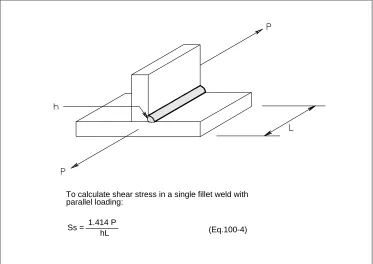
Fig. 100-30 Single Fillet Weld with Parallel Loading (Courtesy of the American Welding Society)
To calculate shear stress in a single fillet weld with parallel loading:
Ss = 1.414 P
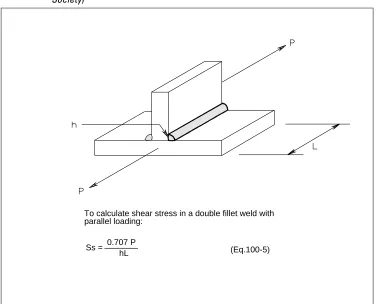
Fig. 100-31 Double Fillet Weld with Parallel Loading (Courtesy of the American Welding Society)
To calculate shear stress in a double fillet weld with parallel loading:
Ss = 0.707 P
127 Joint Terminology and Welding Symbols
[image:40.612.151.523.168.700.2]This section (Figures 100-32 through 100-37) shows AWS descriptions and termi-nology for single groove weld joints and double groove weld joints, along with welding positions for groove welds, fillet welds, and pipe welds. It also shows stan-dard welding symbols used for describing weld joint requirements.
Fig. 100-32 Single Groove Weld Joints (Courtesy of the American Welding Society)
(A)
Single-square-groove weld
(B)
Single-bevel-groove
(C)
Single-V-groove weld
(D)
Single-V-groove weld
(E)
Single-J-groove weld
(F)
Fig. 100-34 Welding Positions for Groove Welds
(Courtesy of the American Welding Society)
Fig. 100-35 Welding Positions for Fillet Welds
130 Weld Metal Composition
In general, all the steels and alloys permitted by the various codes and standards and used by the Company can be welded when using the proper welding procedures. Data sheets for many of these alloys are given in the Alloy Fabrication Data in Appendix A. The data sheets summarize the applicable ASTM and ASME specifi-cations, give the range of chemical composition and mechanical properties, and give welding requirements such as preheat, heat treatment, welding processes and filler metal selection. Other information on filler metal selection is also covered in Section 300, Welding Practices.
131 Filler Metals
Filler metals are usually selected to be similar to the parent material in composition and mechanical properties, but weld metal composition may vary where:
• Difficult to weld materials are encountered (e.g., welding 13 Cr material with austenitic or Ni-Cr-Fe electrodes)
• Special mechanical properties are required (e.g., carbon steel in low tempera-ture applications where low Ni electrodes are used)
• Dissimilar metal combinations are involved (e.g., welding carbon steel to stain-less steel with Ni-Cr-Fe electrodes)
The American Welding Society has thirty-one specifications covering filler metals. There are specifications covering nonconsumable tungsten and carbon electrodes, and for fluxes for brazing, SAW and ESW. The specifications are periodically updated and a two-digit suffix indicating the year issued is added to the specifica-tion number. Figure 100-38 shows the welding process or processes discussed for which each specification is intended.
ASME also issues filler metal specifications in Section II, Part C of the Boiler and Pressure Vessel Code. These are identical with the AWS specifications. ASME filler metal specifications are identified by the prefix letters SF added to the AWS specifi-cation number (e.g., SFA5.1).
The AWS classification system for filler metals uses the following prefixes to indi-cate the product form, the joining process, or both:
Indicates an arc welding electrode that carries the welding current. The electrodes can be flux covered, bare, composite or flux cored and are used for SMAW, GMAW, FCAW, GTAW, and SAW welding.
R– Indicates a welding rod that is heated by means other than by carrying the arc welding current.
ER– Indicates a filler metal that may be used either as an arc welding electrode (carrying the current) or as a welding rod.
RB– Indicates a filler metal that may be used as a welding rod or as a brazing filler metal or both.
RG– Indicates a welding rod to be used in oxyfuel gas welding. F– Indicates a flux for use in SAW.
[image:47.612.90.566.200.683.2]IN– Indicates a consumable insert.
Fig. 100-38 AWS Filler Metal Specifications and Respective Welding Processes (Courtesy of the American Welding Society)
Spec. Specification Title OFW SMAW GTAW GMAW SAW
A5.1 Carbon steel covered arc welding electrodes X
A5.2 Iron and steel gas welding rods X
A5.3 Aluminum and aluminum alloy arc welding electrodes X
A5.4 Corrosion-resisting chromium and chromium-nickel steel covered welding
electrodes
X
A5.5 Low alloy steel covered arc welding electrodes X
A5.6 Copper and copper alloy covered electrodes X
A5.7 Copper and copper alloy welding rods X X
A5.8 Brazing filler metal
A5.9 Corrosion-resisting chromium and chromium-nickel bare and composite metal
cored and standard arc welding electrodes and rods
X X X
A5.10 Aluminum and aluminum alloy welding rods and bare electrodes X X X
A5.11 Nickel and nickel alloy covered welding electrodes X
A5.12 Tungsten arc welding electrodes X
A5.13 Surfacing welding rods and electrodes X X
A5.14 Nickel and nickel alloy bare welding rods and electrodes X X X X
A5.15 Welding rods and covered electrodes for welding cast iron X X
A5.16 Titanium and titanium alloy bare welding rods and electrodes X X
A5.17 Bare carbon steel electrodes and fluxes for submerged-arc welding X
A5.18 Carbon steel filler metals for gas shielded arc welding X X
A5.19 Magnesium alloy welding rods and bare electrodes X X X
A5.20 Carbon steel electrodes for flux cored arc welding X(1)
A5.21 Composite surfacing welding rods and electrodes X X X
A5.22 Flux cored corrosion-resisting chromium and chromium-nickel steel electrodes X1
A5.23 Bare low alloy steel electrodes and fluxes for submerged arc welding X
A5.24 Zirconium and zirconium alloy bare welding rods and electrodes X X
A5.25 Consumables used for electroslag welding of carbon and high-strength low
alloy steels
A5.26 Consumables used for electrogas welding of carbon and high-strength low
alloy steels
X(2)
A5.27 Copper and copper alloy gas welding rods X
A5.28 Low alloy steel filler metals for gas-shielded arc welding X X
A5.29 Low alloy steel flux cored welding electrodes X1
A5.30 Consumable inserts X
132 SMAW Electrodes
The covered electrode for SMAW provides both the filler metal and the shielding gas. Covered electrodes have various core wire compositions and a wide variety of flux coating types. The core wire provides the filler metal for the weld. The flux coating performs one or all of the following functions, depending on the type of electrode:
• Provides shielding gas to prevent contamination of the arc stream and weld metal by oxygen and nitrogen in the atmosphere.
• Forms a slag blanket over the molten puddle and solidified weld. • Provides ionizing elements for smoother arc operation.
• Provides deoxidizers and scavengers to refine the grain structure of the weld metal.
• Provides alloying elements such as molybdenum, nickel, and chromium for low alloy steels.
• Provides iron powder for higher deposition rates.
For carbon steel electrodes, a four digit system is used. See Figure 100-39 for a list of AWS A5.1 SMAW carbon steel electrodes. The first two digits indicate the approximate minimum as-welded tensile strength of the weld metal in ksi (e.g., E60XX or E70XX). The third and fourth digits indicate the electrode coating type. The coating type determines usable welding positions, welding characteristics, and the type of power supply required. For example, E6010 is a 62,000 psi minimum tensile strength electrode with a cellulosic coating. It can be used in all positions, it has a strong deep penetrating arc, and is used on DC reverse polarity. E7018 is a 72,000 psi minimum tensile strength electrode with a low hydrogen, iron powder coating. It can be used in all positions, it has a smooth arc with medium penetra-tion, and is used on DC reverse polarity.
Low alloy steel electrodes are covered by AWS Specification A5.5, which uses a
classification system similar to that for carbon steel with the addition of a suffix for chemical composition. See Figure 100-40 for an abbreviated list of AWS A5.5 SMAW low alloy steel electrodes. Higher strength electrodes, with a minimum tensile strength of 100,000 psi and above, use five digits (e.g., E10018-D2). The first three digits stand for tensile strength. The minimum tensile strength can be for either the as-welded or PWHT condition, depending on the classification. The suffix can be a letter and number designation or a letter only, and designates the chemical composition that it must meet. For example, E8018-B2 is a low hydrogen, iron powder electrode with a nominal composition of 1-1/4 Cr-1/2 Mo, and E8010-G is a cellulosic electrode with a general classification that is required only to have the minimum amount of one of the elements listed (the actual composition is left to the electrode manufacturer).
Stainless steel electrodes are covered by AWS Specification A5.4 (for
Fig. 100-39 AWS A5.1—SMAW Electrodes for Carbon Steel (Courtesy of the American Welding Society)
Classification Coating Type Position Current
Strength, ksi
Elongation,
min. percent Characteristics
Tensile Yield
E6010
Cellulose-sodium
all DCep 62 50 22 Strong, deep-penetrating arc.
Thin slag chips off. Fillets are flat. Spatter at high amperages.
E6011
Cellulose-potassium
all AC,
DCep
62 50 22 Same as E6010, but usable AC.
Less penetration with DCep. Spatter at high amperages.
E6012 Titania-sodium all AC,
DCen
67 55 17 Medium penetration. Dense
slag. Fillets are convex. Weld metal less ductile, stronger than for E6010 and E6011. Little spatter at high amperages.
E6013
Titania-potassium
all AC,
DCep, DCen
67 55 17 Easier slag removal than for
E6012, smoother arc.
E6027 Iron-oxide, iron-powder flat, horizontal fillet AC, DCen
62 50 22 Iron-powder cover. Medium
penetration, low spatter loss. Heavy slag peels off. High amperage. E7014 Iron-powder titania all AC, DCep, DCen
72 60 17 Similar to E6012 and E6013 with
iron-powder addition for higher deposition. Higher amperages. Medium penetration. Slag peels off.
E7016(1) Low hydrogen,
potassium
all AC,
DCep
72 60 22 Low hydrogen. Medium
pene-tration. Slag chips off. Convex weld face.
E70181 Low hydrogen,
potassium, iron-powder
all AC,
DCep
72 60 22 Iron-powder covering. Low
hydrogen. Smooth arc.
E70241 Iron-powder,
titania flat, horizontal fillet AC, DCep, DCen
72 60 17 High iron-powder content. Low
penetration. Quiet arc.
E7028 Low hydrogen,
potassium, iron-powder flat, horizontal fillet AC, DCep
72 60 22 Similar to E7018, but heavy
iron-powder content in coating. Slag chips off.