Large-Eddy Simulation of MVG Controlled Oblique
Shockwave/Boundary Layer Interaction
Guang Yang 1,a, Jian Fang2,ab, Chaoqun Liu3,c, Yufeng Yao4,d and Lipeng Lu5,a
aNational Key Laboratory of Science and Technology on Aero-Engine Aero-Thermodynamics, School of Energy and
Power Engineering, Beihang University, Beijing, 100191, China
b
Computer Science and Engineering Department, STFC Daresbury Laboratory, Warrington WA4 4AD, United Kingdom
cDepartment of Mathematics, University of Texas at Arlington, Arlington, TX 76019-0408
dFaculty of Environment and Technology, Department of Engineering Design and Mathematics, University of the
West of England, Bristol, BS16 1QY, United Kingdom
Shock wave boundary layer interaction is an ubiquitous and important phenomenon in supersonic and hypersonic flow scheme. In this paper, a Mach 2.5 supersonic boundary layer impinged by an oblique shock wave and its control using Micro Vortex Generator (MVG) is studied by large-Eddy Simulation (LES). A high order cut-cell immersed boundary method combined with Cartesian grid are used to deal with the geometrical complexity of MVG. The method uses a non-uniform-grid finite difference scheme for grid points near the MVG solid boundary. This approach can implement boundary condition at irregular surface without decreasing numerical accuracy, which is important for high Reynolds number boundary layer flow. Results shows that flow structures after the MVG are well captured and shock induced flow separation is successfully reduced with control.
I.
Introduction
hock-wave/boundary layer interaction (SBLI) happens ubiquitously in high-speed vehicles, including transonic airfoils, supersonic engine intakes, turbomachinery, missile base flows[1]. In SBLI flow, the shock wave would exert a strong adverse pressure gradient to the boundary layer and even lead to its separation when the shock is strong enough. SBLI flow are generally considered to have negative effects on vehicle performance. It would lead to severe problems such as drag increase, lift loss, over heating, inlet buzz and buffeting in external flows; total pressure loss and flow rate decrease in internal flows[2]. Especially in the case of shock induced separation (SIS), above mentioned issues become more significant and the low frequency oscillation of the separation bubble and the shock can cause structure fatigue and damage[3]. Due to its dual importance for both scientific research and industrial practice, over the past sixty years, much research effort have been dedicated to different kinds of SBLI flow and its control.
As a traditional separation control device, Micro Vortex Generator (MVG) has the advantages of easy to implement, robust, no need of extra energy. It has achieved great success in incompressible flow control, and been recently applied to high-speed flow regime. To guide the MVG design, a deep understanding of the structures and
1
PhD student, School of Power and Energy, Beihang University, Beijing100191, P.R. China.
2 Research Fellow, School of Power and Energy, Beihang University, Beijing100191, P.R. China. [email protected]
3
Professor, Department of Mathematics, University of Texas at Arlington, Arlington, TX 76019-0408
4 Professor, Department of Engineering Design and Mathematics, University of the West of England, Bristol BS16 1QY, United Kingdom, Associate Fellow [email protected]
mechanism in MVG perturbed flow is essential. Large-Eddy Simulation can resolve large unsteady flow scales with affordable computing power, which makes it an ideal tool for flow mechanism research.
Due to the geometrical singularity of MVG, it is hard to use a body fitted structured mesh. There are several ways to deal with complex geometry in CFD, one way is to use an unstructured mesh, however, it is hard to implement high-order accuracy scheme on unstructured mesh. Another way is to use Immersed Boundary Method (IBM) on a Cartesian grid[4]. Traditional IBM use a virtual force to model the effect of boundary on the fluid, and incorporates a discrete representation of Dirac Delta function on the interface, thus leads to a smeared interface with one mesh width thickness. Such method is locally first-order accurate at the interface, which is not suitable for the current boundary layer flow simulation. To resolved the decreased accuracy problem with smeared interface, some “sharp interface” Cartesian grid methods have been proposed by different researchers then. A high-order cut-cell immersed boundary method proposed by Zhong et al[5] is combined with high fidelity LES in this paper, to deal with the geometrical complexity, while keep a high-order accuracy.
II.
Numerical Methods
Numerical Schemes
The governing equations are an estimated form of the grid-filtered dimensionless compressible Navier-Stokes equations:
where is the subgrid-scale (SGS) stress tensor and is the SGS heat flux and defined as:
The SGS model used in present simulation is the Mixed-Time-Scale model by Inagaki et al[6]. The detailed derivation of the above equation and the validity of the estimation can be found in Vreman et al.[7]
The above equations are solved by using an in-house high-order finite-difference code SBLI. The code employs a fourth-order central difference scheme to calculate derivatives at internal points. Close to boundaries, a stable boundary treatment by Carpenter et al.[8] is applied, giving the overall fourth-order accuracy. Time integration is based on a third-order compact storage Runge-Kutta method[9]. An entropy splitting approach of Sandham et al.[10]
is used to calculate the nonlinear terms, which will guarantee the stability of the algorithm. A TVD shock capturing scheme and the artificial compression method (ACM) of Yee et al.[11], coupled with the Ducros sensor[12], are implemented in the code to handle shock-waves and contact discontinuities. The code is made parallel using the MPI library. A multi-block version of the code was extensively validated by Yao et al.[13]
As for the boundary condition, periodic boundary conditions are used in the spanwise direction. At the wall, the no-slip condition is enforced. Furthermore, the wall is considered isothermal with a temperature close to the upstream adiabatic value (assuming a recovery factor of 1). The top (free-stream) and outflow boundaries make use of the characteristic non-reflecting boundary condition[14] in order to minimize unwanted reflections from the computational-box boundaries. The oblique shock-wave is introduced at the top boundary using the Rankine– Hugoniot relationships. The turbulent inflow turbulence is generated using a digital filter method[15] in present simulation.
Cut-cell immersed boundary method
A high-order cut-cell method is adopted to deal with the geometrical complexity. The original computational domain and grid are transformed to a uniform Cartesian grid, and the transformed governing equation is solved on this uniform Cartesian grid. The immersed complex boundary also have a corresponding image in the new grid.
In the current high-order cut-cell finite-difference method, grid points are divided into four categories according to their position relative to the fluid-solid interface, as shown in Figure 1.
Dropped points: Grid points adjacent to a boundary point with a distance smaller than a pre-specified threshold. It is removed from the grid stencil in the corresponding direction. All the grid points on the solid side are also defined as dropped points. They do not participate in any numerical calculation.
[image:3.612.180.455.132.319.2] Regular points: All the other remained grid point of the original Cartesian mesh are defined as regular points, where a standard finite difference scheme can be applied.
Figure 1 grid point categories
Assume that each stencil have q grids near the boundary, then there are [q/2] irregular points near a boundary surface. Figure 2 shows a 5-point non-uniform grid stencil in one direction near the solid boundary. is the boundary point, the blue point is a dropped point, red points and are irregular points and the green points
and are regular points, a uniform parameter is defined as:
the finite-difference coefficients on this stencil are expressed as function of . The general formulation of finite-difference scheme on a non-uniform-grid for irregular points can be written as:
The detailed formulation of for numerical schemes of different accuracy-order can be found in the paper of Zhong et al[16].
On the boundary points, the no-slip wall condition and isothermal temperature are applied, and an approximation assumption of zero pressure gradients is used to determine the pressure on the wall.
Figure 2 Schematic of grid stencil near the solid boundary
Validation
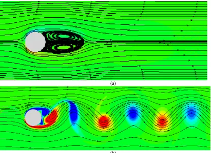
[image:3.612.163.462.500.554.2](a)
[image:4.612.94.509.70.371.2](b)
Figure 3 flow around cylinder at different Reynolds number (a)Re=30.0 (b)Re=400.0
III.
Results
The base flow without control is an oblique shock-wave generated by an 8° wedge impinging onto a Mach 2.3 turbulent boundary layer. Figure 4 shows the time and spanwise averaged density field. The white dashed line is the average sonic line and the black solid line is the contour line of that marks the average separation bubble boundary. Figure 5 shows the mean streamwise velocity profile at x = 260mm which is supposed to be fully developed equilibrium turbulent boundary layer before the interaction. It can be seen that the LES computation results are in good agreement with that from the PIV measurement of Dupont et al. Also the van-Driest transformed velocity profile agrees well with the Log-Law of the wall. Figure 6 shows the instantaneous numerical Schlieren (by using density gradient magnitude) and the streamwise velocity fluctuation at the plane of y+ = 15. The shock-wave system is clearly captured and the typical low-speed streaks of the equilibrium turbulent boundary layer can be clearly observed before entering the interaction region. In the interaction region, the streaks are broken and gradually recovered after the reattachment.
[image:4.612.162.453.590.727.2]Figure 5 Velocity profile at x = 260mm (the superscript * means in dimensional form)
Figure 6 Instantaneous shockwave and boundary layer structure
[image:5.612.161.452.478.659.2]IV.
Conclusion
A high-order cut-cell immersed boundary method is implemented and combined with a high-fidelity Large-Eddy Simulation to study the MVG controlled oblique shockwave/boundary layer interaction. Both the immersed boundary method and the LES have been carefully validated. The a MVG is deposited before the interaction point to control the shock-induced flow separation. The MVG geometrical parameters studied is the same as that used in Babinsky et al’s experiment. It is expected that the results would contribute to the application of immersed boundary method in supersonic flow, and also reveal the control mechanism of MVG.
.
References
1. Dolling David S, "Fifty years of shock-wave/boundary-layer interaction research: what next?". AIAA journal, 2001. 39(8): p. 1517-1531.
2. Babinsky Holger and John K Harvey, Shock wave-boundary-layer interactions. Vol. 32. 2011: Cambridge University Press.
3. Clemens Noel T and Venkateswaran Narayanaswamy, "Low-frequency unsteadiness of shock wave/turbulent boundary layer interactions". Annual Review of Fluid Mechanics, 2014. 46: p. 469-492.
4
. Mittal Rajat and Gianluca Iaccarino, "Immersed boundary methods". Annu. Rev. Fluid Mech., 2005. 37: p. 239-261.
5. Duan Le, Xiaowen Wang, and Xiaolin Zhong, "A high-order cut-cell method for numerical simulation of hypersonic boundary-layer instability with surface roughness". Journal of computational physics, 2010. 229(19): p. 7207-7237.
6. Inagaki Masahide, Tsuguo Kondoh, and Yasutaka Nagano, "A mixed-time-scale SGS model with fixed model-parameters for practical LES". Journal of fluids engineering, 2005. 127(1): p. 1-13.
7. Vreman B. , "Direct and large-eddy simulation of the compressible turbulent mixing layer". PhD thesis,
Department of Applied Mathematics, University of Twente., 1995.
8. Carpenter Mark H, Jan Nordström, and David Gottlieb, "A stable and conservative interface treatment of arbitrary spatial accuracy". Journal of Computational Physics, 1999. 148(2): p. 341-365.
9. Gottlieb Sigal and Chi-Wang Shu, "Total variation diminishing Runge-Kutta schemes". Mathematics of
computation of the American Mathematical Society, 1998. 67(221): p. 73-85. 10
. Yee HC and Björn Sjögreen, Designing adaptive low-dissipative high order schemes for long-time integrations, in Turbulent Flow Computation. 2002, Springer. p. 141-198.
11. Yee Helen C, Neil D Sandham, and MJ Djomehri, "Low-dissipative high-order shock-capturing methods using characteristic-based filters". Journal of Computational Physics, 1999. 150(1): p. 199-238.
12. Ducros F., Ferrand, V., Nicoud, F., Weber, C., Darracq, D., Gacherieu, C., Poinsot, T., "Large-eddy simulation of the shock/turbulence interaction". Journal of Computational Physics, 1999. 152(2): p. 517-549.
13. Yao Y., Shang, Z., Castagna, J., Sandham, N. D., Johnstone, R., Sandberg, R. D., Suponitsky, V., Redford, J. A., Jones, L. E., and De Tullio, N. , "Re-engineering a DNS code for high-performance computation of turbulent flows". Proceedings of the 47th Aerospace Sciences Meeting Including the New Horizons Forum and Aerospace
Exposition 2009(AIAA 2009-566).
14. Poinsot T J, amp, and SK Lelef, "Boundary conditions for direct simulations of compressible viscous flows".
Journal of computational physics, 1992. 101(1): p. 104-129.
15. Touber E. and N. D. Sandham, "Large-eddy simulations of an oblique shock impinging on a turbulent boundary layer: low-frequency mechanisms". 2008.
16. Zhong Xiaolin and Xiaowen Wang, "Direct numerical simulation on the receptivity, instability, and transition of hypersonic boundary layers". Annual Review of Fluid Mechanics, 2012. 44: p. 527-561.
17
![Figure 1 grid point categories Assume that each stencil have q grids near the boundary, then there are [q/2] irregular points near a boundary](https://thumb-us.123doks.com/thumbv2/123dok_us/601711.560270/3.612.163.462.500.554/figure-categories-assume-stencil-boundary-irregular-points-boundary.webp)