Quantitative Transformation for Implementation of
Adder Circuits in Physical Systems
Jeff Jones, James G.H. Whiting, Andrew Adamatzky
Centre for Unconventional Computing University of the West of England
Coldharbour Lane Bristol, BS16 1QY, UK.
{jeff.jones, james.whiting, andrew.adamatzky}@uwe.ac.uk
Abstract
Computing devices are composed of spatial arrangements of simple funda-mental logic gates. These gates may be combined to form more complex adding circuits and, ultimately, complete computer systems. Implementing classical adding circuits using unconventional, or even living substrates such as slime mould Physarum polycephalum, is made difficult and often impracti-cal by the challenges of branching fan-out of inputs and regions where circuit lines must cross without interference. In this report we explore whether it is possible to avoid spatial propagation, branching and crossing completely in the design of adding circuits. We analyse the input and output patterns of a single-bit full adder circuit. A simple quantitative transformation of the input patterns which considers the total number of bits in the input string allows us to map the respective input combinations to the correct outputs patterns of the full adder circuit, reducing the circuit combinations from a 2:1 mapping to a 1:1 mapping. The mapping of inputs to outputs also shows an incremental linear progression, suggesting its implementation in a range of physical systems. We demonstrate an example implementation, first in simulation, inspired by self-oscillatory dynamics of the acellular slime mould
Physarum polycephalum. We then assess the potential implementation using plasmodium of slime mould itself. This simple transformation may enrich the potential for using unconventional computing substrates to implement digital circuits.
1. Introduction
Classical computing devices are based on spatial arrangements of sim-ple fundamental Boolean logic gates, typically imsim-plemented on planar silicon substrates using electronic signalling. The logic gates may be combined to form more complex adding circuits and, ultimately, complete computer sys-tems. Classical computing devices are notable for their miniaturisation and integration, and the speed of operation. Although the dominant form of computation, alternatives to classical computing schemes exist in a number of different physical systems, and indeed proliferate in many living systems. Such non-classical, or unconventional, computing mechanisms take advan-tage of different computing features within these substrates, such as natural parallelism, morphologically adaptive patterning, self-organisation and emer-gent behaviour.
Implementing classical Boolean operations in such substrates is not nec-essarily a good computational ‘fit’ in that it does not lend itself to the ad-vantages of these substrates (and may indeed exacerbate the disadad-vantages). Nevertheless, implementation of Boolean operations and more complex cir-cuitry does demonstrate universality that is a characteristic feature of classi-cal schemes. In recent years there have been numerous examples of individual gates and more complex circuits implemented in unconventional substrates, including Belousov-Zhabotinsky medium [14, 8, 38, 7], competing patterns in Game-like cellular automata [23, 22], patterns of crystallisation [1], dis-ordered ensembles of carbon nanotunes [13], liquid crystals [17, 25, 9], or-ganic molecular layers [11], spiking memristors [16], nuclear magentic reso-nance [12], precipitating reaction-diffusion chemical systems [6], enzymatic systems [37, 21, 26].
syn-chronisation but these mechanisms are not suitable in many unconventional substrates. In some substrates, such as circuits based on the migration of the true slime mould Physarum polycephalum these timing issues can affect the reliable operation of the gates.
In this article we examine the possibility of removing bridging and branch-ing points from the fundamental operation of a common addbranch-ing circuit, the one-bit full adder circuit by utilising a transformation of the input bit pat-terns into a quantitative signal. The quantitative nature of this simple trans-formation may render it suitable in a wide range of computing substrates. An overview of Physarum computing with particular relevance to the approxi-mation of digital logic gates and circuits is described in Section 2. In Section 3 we describe the transformation necessary to implement a quantitative full adder circuit. Section 4 describes experiments using a multi-agent model of slime mould where we assess whether geometric constraints of the organ-ism’s environment are sufficient to generate changes in oscillatory frequency required to implement the quantitative adder.
In Section 5 we perform the same experiments using the organism itself to assess the practicality of implementing the quantitative adder using a living substrate. We conclude in Section 6 by stating the contribution of the article, along with the potential advantages and disadvantages of the approach.
2. Physarum-based Logical Gates and Circuits
The protoplasmic tubes of the acellular slime mould Physarum poly-cephalum have an inherent oscillatory frequency which controls movement by shuttle streaming [15]; this streaming controls the rate and direction of growth for the organism. The mechanism for movement is similar to peristalsis, where contraction causes an advancing frontier of plasmodium; the frequency of peristaltic-like streaming determines direction of movement.
Foraging behavior has been interpreted as intelligence, thus, presenting the organism with a solvable task, can be interpreted as computation [2]. There has recently been a surge of literature puportingPhysarumcomputing, with approaches to plasmodial logic gates based on growth being proposed; Adamatzky has reported protoplasmic tubes act like microfluidic logic gates with mechanical stimulation of tube fragments [10].
Spatial implementation of the full adder circuit using logic gates requires that the path be carefully routed between the individual gates. At certain lo-cations the circuit paths must cross, or bridge, without contaminating other circuit lines. In other instances one circuit must be duplicated to provide input to another gate. Duplication of a circuit is relatively simple in most computing substrates (delay issues notwithstanding) but bridging of circuit paths is not possible, or at least very impractical in certain substrates. This difficulty is particularly manifested in living biocomputing substrates such as the slime mouldPhysarum polycephalum. Individual slime mould logic gates were demonstrated using the growth of Physarum across a substrate with chemoattraction [29], ballistic movement and interaction of the slime mould’s lamellipodia [3] and photoavoidance [24]. Half adder circuits were designed and tested in simulation in [20] and using the Physarum plasmodium [3]; the ballistic slime mould circuits are proved to be substrate independent when implemented in light-sensitive Belousov-Zhabotinsky medium [14]. Difficul-ties in establishing reliable propagation timing and the unpredictability of behaviour at junctions prevent practical usage of the plasmodium for adding circuits. This is compounded by the slow foraging speed of the plasmodium (measured in tens of hours for a single gate) and suggests that spatial im-plementation of logical gates and adding circuits may not be the best fit for this unconventional computing substrate.
indi-cating that the oscillatory threshold logic gates were functionally complete. This improved type ofPhysarumlogic gate shortened computation time from a number of hours to a matter of minutes. The article also demonstrated combinational logic circuits by cascading of the individual tube gates; a 2-4 bit decoder, half-adder and full-adder were shown. Despite overcoming the slow computation time of plasmodium propagation based gates, one limita-tion of the combinalimita-tional logic of cascaded gates remained; while individual gates produced the correct output up to 92% of the time, cascading gates increased the error as the number of gates used increased [32].
If it were possible to find a way to minimise the cascading of gates in implementations of more complex circuits, this would increase the reliability and practicality of biologically implemented digital circuits. We propose and test such a method in the following sections.
3. Transformation of the Single-bit Full Adder Circuit
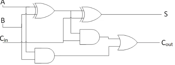
[image:5.612.167.450.483.589.2]The full adder circuit enables the addition of two binary inputs, together with a carry input (for example, from a previous calculation). The carry output may be cascaded to other adder circuits so that larger strings of bits may be added. A typical implementation of a full adder circuit is shown in Fig. 1 composed of XOR, AND and OR gates. Note the complex spatial routing of signals from the input channels and from combined outputs of individual logic gates.
3.1. Quantitative Transformation of Truth Table Input Patterns
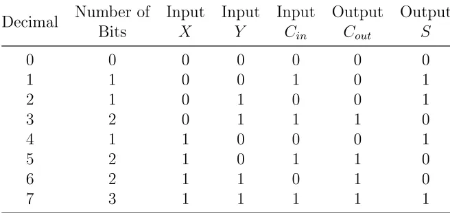
The truth table for the full adder circuit is shown in Table 3.1. In binary terms the full adder may be seen as a 2:1 mapping of the 8 (3-bit) possible input combinations (X, Y, Cin) into 4 (2-bit) possible output combinations
(S, Cout). If we examine the three inputs to the full adder, together with
their corresponding outputs, a pattern can be seen if we ignore the binary values of the inputs, and instead concentrate on the total number of ‘1’ bit digits in the input patterns (Table 3.1, column: number of bits). The number of ‘1’ bits in each combination ranges from zero to three, giving four possible combinations, matching the number of output pattern combinations.
Furthermore, combinations of different inputs which share thesame num-ber of bits all share the same output configuration. For example (referring to Table 3.1) the input patterns which all contain only a single ‘1’ bit (decimal value of patterns 1, 2 and 4) all map to the same output pattern of 0 (Cout)
and 1 (S). Similarly, input patterns which contain two ‘1’ bits (decimal value of patterns 3, 5 and 6) all map to the output patterns of 1 (Cout) and 0 (S).
Decimal Number of Bits Input X Input Y Input Cin Output Cout Output S
0 0 0 0 0 0 0
1 1 0 0 1 0 1
2 1 0 1 0 0 1
3 2 0 1 1 1 0
4 1 1 0 0 0 1
5 2 1 0 1 1 0
6 2 1 1 0 1 0
[image:6.612.138.466.375.530.2]7 3 1 1 1 1 1
Table 1: Single-bit full adder truth table including decimal value of input combinations and the quantitative number of 1 bits in each input combination.
The mapping removes the need for spatial re-routing of separate components of the adder circuit (for example, in Fig. 1 both inputs ’A’ and ’B’ are du-plicated and passed to more than one gate, whilst input ’C’ is fed forward to combine with the output of the first XOR gate and also split to become an input for the second AND gate). Importantly, this mapping of input to output values is also identical in that they both follow an incremental pro-gression. This suggests that it might be possible to use a physical mechanism to perform the computation of the adder circuit. That is, the transformed input could be encoded in a single signal line carrying a weighted non-binary signal.
Number of
Bits Cout S
Decimalised Outputs
0 0 0 0
1 0 1 1
2 1 0 2
[image:7.612.213.395.283.383.2]3 1 1 3
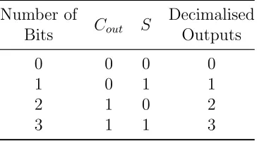
Table 2: Mapping quantitatively transformed input combinations into truth table outputs. Left column shows the total number of bits in the X,Y and Cin inputs. Middle columns
(CoutandS) are binary outputs. Right column shows the decimal values of the two binary
outputsCout andS.
3.2. Towards Physical Mechanisms for Quantitative Adder Circuits
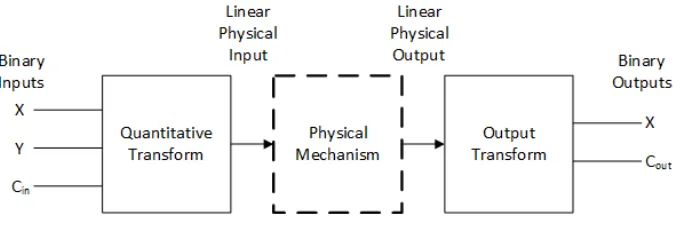
A physical implementation of the adder circuit must relate the number of input bits to an increase in some physical value. This value could be changes in light intensity, an increase in pressure, and so on. . . To return the output to the binary domain the relevant output map ‘bin’ must be transformed into binary values in order to pass the S and Cout on to the next gate (Fig.
2). This conversion adds complexity at the interface of the circuit, but this is balanced by the increased simplicity within the adder circuit itself.
4. Implementation of the Mechanism in a Model of Physarum polycephalum
multi-Figure 2: Schematic illustration of quantitative adder mechanism. Binary inputs (left) are transformed into a linear physical quantity which is passed to physical system implemen-tation (dashed) whose output is transformed to a binary represenimplemen-tation (right).
agent approach is inspired by the simple components of the Physarum plas-modium and is composed of a population of simple mobile particles indirectly coupled within a diffusive lattice. Agents loosely correspond to aggregates of overlapping actin filaments. Their collective structure of the population corresponds to the pattern of the tube networks of the plasmodium and the collective movement of particles corresponds to the sol flux within the plas-modium. A full description of the model is given in the appendix and below we concentrate on the transformations of binary values at the inputs to the adder circuit and the subsequent interpretation of the changes in behaviour of the model as the outputs of the circuit.
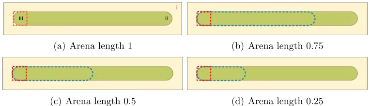
[image:8.612.138.479.129.242.2]The quantitative input values mapped from 0 to 3 (from inputs of Fig. 3.1) are transformed into a physical representation by only allowing move-ment of particles which occupy smaller regions of the arena (elongated dashed regions in Fig. 3b, c and d). These regions represent decreasing fractions of the original length of the arena.
(a) Arena length 1 (b) Arena length 0.75
[image:9.612.114.496.210.320.2](c) Arena length 0.5 (d) Arena length 0.25
Figure 3: Geometrically constraining arena of the model plasmodium. a) schematic of model arena with non-habitable area (i), habitable region (ii) and sampling window (iii, dashed red, online) indicated, b,c,d) Constrained habitable region (dashed blue, online) of 0.75, 0.5 and 0.25 the original arena length.
If the geometric constraints of the arena represent the binary input trans-formation, how is the physical behaviour which generates the individual out-put bins represented? We can represent this in the model plasmodium by measuring the frequency of oscillations within the arena. The Physarum
plasmodium, when confined in a suitably shaped arena, exhibits regular oscil-lations of thickness at each end of the arena [28]. These thickness osciloscil-lations emerge from initially random contractions of the plasmodium strand which propel sol throughout the strand. There is a reciprocal relationship between contractile activity and strand thickness (presumably due to the stretch ac-tivation phenomenon of the tube strand) as contraction of the tube results in transport of sol away from the contraction site and a subsequent decrease in strand thickness.
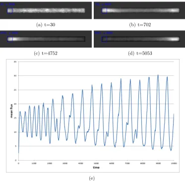
particle efflux) allows greater freedom of movement and so flux increases in these regions. The result is a gradual emergence of small oscillatory domains Fig. 4a) which fuse and become entrained Fig. 4b) until a single large oscilla-tion traverses the arena from end to end Fig. 4c, d). The dominant frequency of this stable oscillation Fig. 4e) can be measured by FFT transform and spectral analysis.
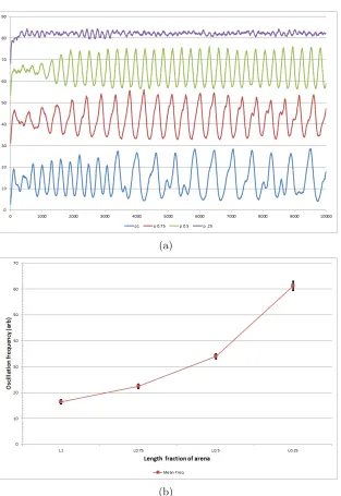
When the model plasmodium is geometrically constrained using the pat-terns in Fig. 3 the dominant oscillatory frequency increases as arena length decreases. An example plot of the oscillatory patterns for decreasing arena length is shown in Fig. 5a. When the oscillation data (10 runs at each arena length fraction) is analysed in the frequency domain, the frequency of oscillations does indeed increase as the arena length decreases. Although the relationship is not perfectly linear (Fig. 5b), a simple thresholding of oscillation frequency should be sufficient to represent the output bins of the quantitative adder.
Although this example uses changing oscillation frequency in a model of
Physarum plasmodium to represent the physical system, the quantitative concept is applicable to any physical system with approximately linear pro-gression. For example, constraining the geometry of the model plasmodium is suggestive of changing the dominant frequency of a resonant cavity by altering its size.
5. Experimental Implementation with Plasmodium of Slime Mould
The plasmodial phase of the organism was cultured on 2% non-nutrient agar, from an initial dried sclerotia, in 9cm diameter Petri-dishes (Sigma-Aldrich, MO, USA). The plasmodium was fed daily with a small number of sterile rolled oat flakes and transplanted to a new Petri-dish every week thus avoiding contamination.
(a) t=30 (b) t=702
(c) t=4752 (d) t=5053
[image:11.612.118.491.160.525.2](e)
(a)
[image:12.612.151.464.122.577.2](b)
Figure 6: Artistic representation of the Petri-dish used to grow tubes of fractional lengths.
pairs of hemispheres and allowed to grow across the gap after which the bio-electric potential was measured. Each tube was measured using a PicoLog ADC-24 high resolution analogue-to-digital data logger (Pico Technology, UK); recording was performed via USB to a laptop installed with the be-spoke PicoLog Recorder software. Frequency analysis was performed on the recorded voltage output using custom software written in Matlab R2012A, which consisted of frequency analysis using the Fast-Fourier Transform func-tion and graphical display. For each geometrical length fracfunc-tion, a total of 10 individual tubes were grown, measured and analysed. The results of fre-quency analysis for each length is shown in figure 7, oscillation frefre-quency decreases with increasing length; linear regression shows that there is a lin-ear trend through the data with the equation Y = −0.0015X + 0.0109 and an R2 value of 0.8107.
fractions used in the model. The non-linear nature of the model may be observed in different lengths of real protoplasmic tubes should a different set of lengths have been used, however the tubes grow in the experimental conditions were within the range of known protoplasmic tubes which can be reliably and repeatably used. The very similar relationship between the model and experimental data assures validation of the model thus the concept of quantitative transformation for physical systems including but not limited to Physarum computation.
6. Conclusions
with the added complexity of implementing a transform to enable the binary input patterns to be presented to, and read from, the physical system which implements the circuit. The generality of the method, however, suggests it is possible to implement the adder circuit in a number of different physical substrates. In future work it may be possible to apply the approach to more complex circuits and directly pipe the output of one circuit to another in the pipeline without recourse to transforming the values back to the binary domain.
Acknowledgements
[1] Andrew Adamatzky. Hot ice computer. Physics Letters A, 374(2):264– 271, 2009.
[2] Andrew Adamatzky. Physarum Machines: Computers from Slime Mould. World Scientific Publishing Co. Pte. Ltd., London, 2010.
[3] Andrew Adamatzky. Slime mould logical gates: exploring ballistic ap-proach. arXiv preprint arXiv:1005.2301, 2010.
[4] Andrew Adamatzky. Slime mould tactile sensor. Sensors and Actuators B: Chemical, 188:38–44, November 2013.
[5] Andrew Adamatzky. Towards slime mould colour sensor: Recognition of colours by physarum polycephalum. Organic Electronics, 14(12):3355 – 3361, 2013.
[6] Andrew Adamatzky and Benjamin De Lacy Costello. Experimental logical gates in a reaction-diffusion medium: The xor gate and beyond.
Physical Review E, 66(4):046112, 2002.
[7] Andrew Adamatzky, Ben De Lacy Costello, Larry Bull, and Julian Hol-ley. Towards arithmetic circuits in sub-excitable chemical media. Israel Journal of Chemistry, 51(1):56–66, 2011.
[8] Andrew Adamatzky, Julian Holley, Peter Dittrich, Jerzy Gorecki, Ben De Lacy Costello, Klaus-Peter Zauner, and Larry Bull. On architectures of circuits implemented in simulated Belousov–Zhabotinsky droplets.
BioSystems, 109(1):72–77, 2012.
[9] Andrew Adamatzky, Stephen Kitson, Ben De Lacy Costello, Mario Ar-iosto Matranga, and Daniel Younger. Computing with liquid crystal fingers: Models of geometric and logical computation. Physical Review E, 84(6):061702, 2011.
[10] Andrew Adamatzky and Theresa Schubert. Slime mold microfluidic logical gates. Materials Today, 17(2):86–91, March 2014.
[12] Matthias Bechmann, Angelika Sebald, and Susan Stepney. Boolean logic gate design principles in unconventional computers: an NMR case study.
IJUC, 8(2):139–159, 2012.
[13] Hajo Broersma, Faustino Gomez, Julian Miller, Mike Petty, and Gun-nar Tufte. Nascence project: Nanoscale engineering for novel computa-tion using evolucomputa-tion. International journal of unconventional computing, 8(4):313–317, 2012.
[14] Ben De Lacy Costello, Andy Adamatzky, Ishrat Jahan, and Liang Zhang. Towards constructing one-bit binary adder in excitable chemical medium. Chemical Physics, 381(1):88–99, 2011.
[15] A.C.H. Durham and E.B. Ridgway. Control of chemotaxis in Physarum polycephalum. The Journal of Cell Biology, 69:218–223, 1976.
[16] Ella Gale, Ben de Lacy Costello, and Andrew Adamatzky. Is spiking logic the route to memristor-based computers? In Electronics, Circuits, and Systems (ICECS), 2013 IEEE 20th International Conference on, pages 297–300. IEEE, 2013.
[17] Simon Harding and Julian F Miller. Evolution in materio: Evolving logic gates in liquid crystal. In Proc. Eur. Conf. Artif. Life (ECAL 2005), Workshop on Unconventional Computing: From cellular automata to wetware, pages 133–149. Beckington, UK, 2005.
[18] J. Jones. Characteristics of pattern formation and evolution in approxi-mations ofPhysarumtransport networks. Artificial Life, 16(2):127–153, 2010.
[19] J. Jones. The emergence and dynamical evolution of complex transport networks from simple low-level behaviours. International Journal of Unconventional Computing, 6(2):125–144, 2010.
[20] J. Jones and A. Adamatzky. Towards Physarum binary adders. Biosys-tems, 101(1):51–58, 2010.
[22] Genaro J Mart´ınez, Andrew Adamatzky, Kenichi Morita, and Maurice Margenstern. Computation with competing patterns in life-like automa-ton. InGame of Life Cellular Automata, pages 547–572. Springer, 2010.
[23] Genaro J Mart´ınez, Kenichi Morita, Andrew Adamatzky, and Maurice Margenstern. Majority adder implementation by competing patterns in life-like rule b2/s2345. In Unconventional Computation, pages 93–104. Springer, 2010.
[24] R. Mayne and A. Adamatzky. Slime mould foraging behaviour as opti-cally coupled logical operations. International Journal of General Sys-tems, 44(3):305–313, 2015.
[25] Julian F Miller, Simon L Harding, and Gunnar Tufte. Evolution-in-materio: evolving computation in materials. Evolutionary Intelligence, 7(1):49–67, 2014.
[26] Valber Pedrosa, Dmitriy Melnikov, Marcos Pita, Jan Halamek, Vladimir Privman, Aleksandr Simonian, and Evgeny Katz. Enzymatic logic gates with noise-reducing sigmoid response. IJUC, 6(6):451–460, 2010.
[27] S. Takagi and T. Ueda. Emergence and transitions of dynamic pat-terns of thickness oscillation of the plasmodium of the true slime mold Physarum polycephalum. Physica D, 237:420–427, 2008.
[28] A. Takamatsu, T. Fujii, H. Yokota, K. Hosokawa, T. Higuchi, and I. Endo. Controlling the geometry and the coupling strength of the oscillator system in plasmodium of Physarum polycephalum by micro-fabricated structure. Protoplasma, 210:164–171, 2000.
[29] S. Tsuda, M. Aono, and Y.-P. Gunji. Robust and emergent Physarum logical-computing. BioSystems, 73:45–55, 2004.
[30] S. Tsuda and J. Jones. The emergence of synchronization behavior in
Physarum polycephalum and its particle approximation. Biosystems, 103:331–341, 2010.
[32] J.G.H. Whiting, B.P.J. de Lacy Costello, and A Adamatzky. Physarum Chip : Developments in growing computers from slime mould. InUCNC: Unconventional Computation in Europe Workshop, page 3, 2014.
[33] J.G.H. Whiting, B.P.J. de Lacy Costello, and A. Adamatzky. Sensory fusion in physarum polycephalum and implementing multi-sensory func-tional computation. Biosystems, 119:45–52, 2014.
[34] J.G.H. Whiting, B.P.J. de Lacy Costello, and A. Adamatzky. Slime Mould Logic Gates Based on Frequency Changes of Electrical Potential Oscillation. Biosystems, 124:21–25, 2014.
[35] J.G.H. Whiting, B.P.J. de Lacy Costello, and A. Adamatzky. Towards slime mould chemical sensor: Mapping chemical inputs onto electrical potential dynamics of physarum polycephalum. Sensors and Actuators B: Chemical, 191:844–853, 2014.
[36] J.G.H. Whiting, B.P.J. de Lacy Costello, and A. Adamatzky. Transfer function of protoplasmic tubes of Physarum polycephalum. Biosystems, 128:48–51, 2015.
[37] Oleksandr Zavalov, Vera Bocharova, Jan Halamek, Lenka Hal´amkov´a, Sevim Korkmaz, Mary A. Arugula, Soujanya Chinnapareddy, Evgeny Katz, and Vladimir Privman. Two-input enzymatic logic gates made sigmoid by modifications of the biocatalytic reaction cascades. IJUC, 8(5-6):347–365, 2012.
7. Appendix: Particle Model Description
We used a multi-agent approach to generate thePhysarum-like behaviour. This approach was chosen specifically specifically because we wanted to re-produce the generation of complex behaviour using very simple component parts and interactions, and no special or critical component parts to gener-ate the emergent behaviour. Although other modelling approaches, notably cellular automata, also share these properties, the direct mobile behaviour of the agent particles renders it more suitable to reproduce the flux within the plasmodium. The multi-agent particle model of Physarum used to generate the oscillatory dynamics [19] uses a population of coupled mobile particles with very simple behaviours, residing within a 2D diffusive lattice. The lat-tice stores particle positions and the concentration of a local diffusive factor referred to generically as chemoattractant. Particles deposit this chemoat-tractant factor when they move and also sense the local concentration of the chemoattractant during the sensory stage of the particle algorithm. Collec-tive particle positions represent the global pattern of the material. The model runs within a multi-agent framework running on a Windows PC system. Per-formance is thus influenced by the speed of the PC running the framework. The particles act independently and iteration of the particle population is performed randomly to avoid any artifacts from sequential ordering.
7.1. Generation of Virtual Plasmodium Cohesion and Oscillatory Rhythm
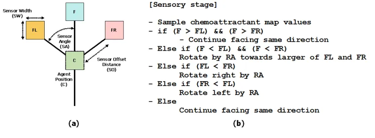
from 0–360◦) by a single pixel forwards. Each lattice site may only store a single particle and particles deposit chemoattractant into the lattice (5 units per step) only in the event of a successful forwards movement. If the next chosen site is already occupied by another particle move is abandoned and the particle does not deposit any attractant. To generate emergent oscilla-tory dynamics a new direction is not selected if the move is not successful (see [30] for more information about the emergence of oscillatory dynamics within the model).
Figure 8: Architecture of a single particle of the virtual material and its sensory algorithm. (a) Morphology showing agent position ‘C’ and offset sensor positions (FL, F, FR), (b) Algorithm for particle sensory stage.
7.2. Problem Representation