Development of an Experimental Phosphate-Calcium
Cement with a Whisker-Like Structure
Hideaki Narusawa*, Yukimichi Tamaki, Takashi Miyazaki
Department of Conservative Dentistry, Division of Dental Materials and Technology, School of Dentistry, Showa University, Tokyo, Japan.
Email: *null@dent.showa-u.ac.jp
Received August 15th, 2012; revised September 11th, 2012; accepted October 8th, 2012
ABSTRACT
In a previous study, the authors tried to synthesize dental materials from dental waste, which was accomplished with alginate impression materials and gypsum. A powder was set by mixing it with phosphate solution. Fibrous curled crystals were found through SEM observation. The present study shows a detailed analysis of the crystals. XRD analy-sis indicated the crystals are Brushite. A unique profile of the crystal shows it can be a good apatite precursor or cell scaffold; however, this hypothesis requires further examination.
Keywords: Calcium Phosphate; Whisker; Diatomite; Scaffold; DCPD; Brushite; Bone Regenerative
1. Introduction
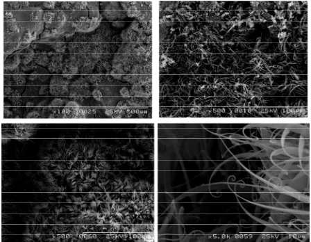
There are several polymorphisms in phosphate calcium ceramics such as DCPD (Brushite), alpha and beta TCP, OCP, and hydroxyapatite. Since these phosphate-calcium ceramics have highly osteo-conductive properties, they have been used frequently as bone filling material, tita- nium implant coating, and dentin regenerative material [1]. Bone regenerative ceramic materials are usually found in porous granule. On the other hand, unique fi- brous (long whisker-like) calcium phosphate ceramics have been developed for application to a scaffold of en- gineered tissue [2]. Calcium-based cement materials have been frequently used in endodontic treatment of dentistry; however, there have been no reports on whisker-like structures in the cements. Our previous study [3] reported on the possibility of recyclable use of daily dental wastes such as in calcium silicate ceramics. Since alginate im- pression material contains silica (diatomite) and calcium salts (gypsum) as components, we synthesized calcium silicate cement material from alginate impression mate- rial. Subsequently, we found that the experimentally fab- ricated calcium silicate powder could be mixed with a phosphoric acid solution and set by depositing the brushite with the whisker-like structure shown in Figure 1. The aim of this study is to confirm the structure of the set product from the experimental calcium silicate pow- der (the prototype) as compared with a reagent calcium silicate powder (the control).
2. Materials and Methods
2.1. Synthesis of Experimental Calcium Silicate Powder (the Prototype)
[image:1.595.311.535.514.688.2]The powder was prepared as follows. First, the powder from commercial alginate impression material (ALGI- ACE, Dentsply Sankin, Tokyo, Japan Lot: 475-861) was mixed with water at a ratio specified by the manufacturer, and the set product was placed in an electric furnace and fired at 800˚C for 3 hours. The fired product was ground into a powder using a mortar and pestle. Next, commer
Figure 1. Pictures were obtained by SEM (S-2360N; Hitachi, Tokyo, Japan) at 25 KV, and are coated with Au-Pd. In spite of the weed-like form, the crystals are inorganic cal- cium phosphate.
cial gypsum powder (Maruishi Gypsum, Tokyo, Japan. Lot: 311109) was added to the obtained powder to adjust the molar ratio of calcium to silicon to 1:1. The blended powder was mixed with water at a ratio of 0.45 and al- lowed to set. The hardened material was placed in an alumina crucible inside a KDF009M electric furnace (Denken Kyoto Japan), where it was fired at a tempera- ture that increased by 30˚C per minute until it reached 1200˚C, and was then kept for 3 hours, followed by grinding in a mortar and pestle to produce the powder. The experimental powder (the prototype) was mixed with a commercial phosphoric acid solution of zinc phosphate cement (Elite cement GC, Tokyo, Japan. Lot: 803031 with a mixture ratio of 1.0). Correspondingly, for the con- trol, 5 grams of reagent calcium silicate powder (Wako Chemical, Tokyo, Japan, Lot: STG0544) was mixed with 5 g of phosphoric acid (Kanto Chemical, Tokyo, Japan, Lot: 701A1090), and 5 ml of distilled water.
2.2. SEM Observations
The morphology of the prototype and the control calcium silicate powder were observed using a MiniScope TM3000 (Low vacuum SEM, Hitachi, Tokyo, Japan). In addition, after removing calcium salts from the prototype and control calcium silicate powder with hydrochloric acid, the morphology of the residual diatomite of the prototype and silica of the control was observed. Fur- thermore, the surface morphology of the set products of the prototype and the control mixed with phosphoric acid solution were observed by SEM. Elemental analysis of the set products of the prototype and control calcium silicate powder mixed with phosphoric acid solution was conducted using the MiniScope TM3000 (Low vacuum SEM, Hitachi, Tokyo, Japan) with SwiftED 3000 Energy dispersive X-ray spectrometry.
2.3. EDX Analysis
Elemental analysis of the set products of the proto-type and control calcium silicate powder mixed with pho- sphoric acid solution was conducted using the MiniScope TM3000 (Low vacuum SEM, Hitachi, Tokyo, Japan) with SwiftED 3000 Energy dispersive X-ray spectro- metry.
2.4. X-Ray Diffraction (XRD) Analysis
To determine the crystal structure of the prototype and control powder, XRD analysis was conducted using a TF device XRD (XRD-6100, Shimadzu, Kyoto, Japan) un- der conditions of 40 kV and 43 mA with CuKα radiation under the scanning range of 10 - 80 degrees. The crystal structure of the set products of the prototype and the con- trol calcium silicate powder mixed with phosphoric acid solution was also analyzed after the set products were
grinded by mortar and pestle.
3. Results and Discussion
Since normal bone filling material has been provided by several manufacturers as a chemically stable powder or in a granular form, the authors attempted to develop a type of bone graft material to be cured by kneading in a previous study [3]. In this study, we found crystals that look like a whisker on hardened material. Similar crystals were found in a paper by Tejima and Oishi [2]. They developed the OCP graft material with a whisker-like structure and expected cells to be induced around the crystals. However, they spend several weeks to synthesize the crystals in a special environment and conditions. Although we have succeeded to generate similar crystals more quickly, there is an uncertainty about how these were generated, and the composition of the crystals. The result of this genaration shows the composition is Brushite, and these crystals were generated from path-through holes in diatomite.
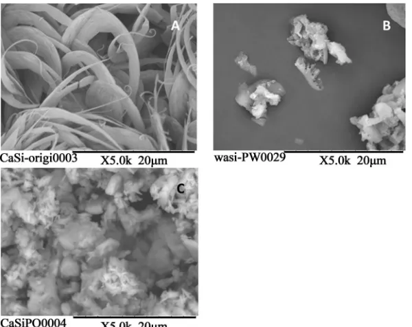
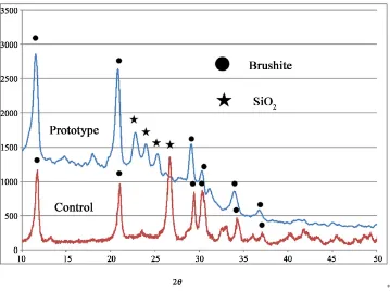
The prototype powder did not show the characteristic shape and size shown in Figure 2(A) (upper left). In con- trast, the control powder had bubbly pores with a diame- ter of approximately 2 - 5 µm as shown in Figure 2(B) (upper right). The acid-treated prototype powder showed a melted, smooth surface; however, the surface had mi- cro pores with a diameter of approximately 2 µm as shown in Figure 2(C) (lower left). The original micro pores of the diatomite still remained after the heat treat- ment and the grinding during the powder preparations. The control powder had no porous structures as shown in Figure 2(D) (lower right). XRD patterns in Figure 3 ap- peared both in the prototype powder and in the control powder and were a mixture of calcium silicate and silica (or silicate compounds). The difference in silica structure between the two powders, known as crystal polymer- phism, depended on the origin of the material, and whether it was bio-synthetic or industrially synthesized. Figure 4 shows a comparison of the SEM pictures of the surface of the set products from the prototype and the control powder and phosphoric acid solution. The unique curled fibrous and whisker-like structure (A) disappeared after acid washing and small diatomite fragments re-mained (B). In contrast, the set product from the control was made of normal aggregates and was not covered with a fibrous or whisker-like structure.
[image:3.595.62.538.85.177.2]
Figure 2. (A) The prototype powder. (B) The control powder. (C) The acid-treated prototype powder. (D) The control powder had no porous structures.
Figure 3. XRD pattern: Prototype and reagent shows similar calcium silicate and silica mixture patterns.
[image:3.595.148.451.214.435.2] [image:3.595.150.450.464.702.2]Table 1. Result of the elemental analysis. MiniScope TM3000 (low vacuum SEM, Hitachi, Tokyo, Japan) with SwiftED 3000 Energy dispersive X-ray spectrometry.
Prototype Control
Element Concentration mol [%]
Carbon 8.02 10.2
Oxygen 72.1 68.9
Aluminum 0.28 N.D
Silicon 0.22 5.64
Phosphorous 9.56 7.95
Sulfur 0.32 N.D
Calcium 9.44 7.38
from the prototype (left). On the other hand, there were many silicon islets detected on the set product from the control (right, red area).
Figure 6 indicated that both samples were covered by Brushite. Silica patterns appeared on the set product from the control, but did not appear on the set product from the prototype.
Both the set products from the control and the proto- type showed the Brushite pattern in XRD; however, the set product from the prototype did not show the silicon islet by element mapping (Figure 5). These findings in- dicate that the thick deposition of Brushite occurred in a direction starting from the surface of the wreckage of diatomite contained in the prototype powder. Since the diatomite had approximately 90% porosity, the liquid of the phosphoric acid solution might be absorbed com- pletely to the pore. In this case, whole phosphorous ions were supplied from the surface holes of the diatomite,
[image:4.595.62.535.130.402.2]
Figure 5. Elemental mapping of the set products from the prototype and the control. Many silicon islets detected on the set product from the control (right, red area). MiniScope TM3000 (low vacuum SEM, Hitachi, Tokyo, Japan) with SwiftED 3000 Energy dispersive X-ray spectrometry.
[image:4.595.120.479.453.722.2]and then the calcium phosphate precipitation progressed from the pore of the diatomite producing the whisker-like structure toward the outer surface. The large surface area of these whisker-shaped crystals can be applied to the scaffold of osteoconductivity. Brushite was reported as a biologic cement [4], and the diatomite does not have an unfavorable side effect. These experimental materials are promising for application to not only bone graft materials, but also materials for endodontic treatments because of the cement application. Evaluation of biocompatibility and bone conductivity will be continued in future re- search.
4. Conclusion
Whisker-like Brushite structures were found in the cal- cium phosphate substance when the powder obtained from the porous diatomite as a starting material was sub- sequently mixed with phosphate. This material could have special effects for clinical application because of its unique shape although further research is needed.
5. Acknowledgements
I am indebted to the staff of the Department of Conserva-
tive Dentistry, Division of Dental Materials and Tech- nology whose research and comments helped me greatly throughout this study. I would also like to express my gratitude to my family for their moral support and warm encouragement.
REFERENCES
[1] G. Cama, F. Barberis, R. Botter, P. Cirillo, M. Capurro, R. Quarto, S. Scaglione, E. Finocchio, V. Mussi and U. Val- busa, “Preparation and Properties of Macroporous Bru- shite Bone Cements,” Acta Biomater, Vol. 5, No. 6, 2009, pp. 2161-2168.
[2] T. Katsuya and O. Shuji, “Calcium Phosphate Based Spherocrystal,” Shinshu University, Nagano, 2009.
[3] N. Washizawa, H. Narusawa, Y. Tamaki and T. Miyazaki, “Production of a Calcium Silicate Cement Material from Alginate Impression Material,” Dental Materials Journal, Vol. 31, No. 4, 2012, pp. 629-634.