A Review of Spectrum Sensing Techniques for
Cognitive Radio
Md. Shahnawaz Shaikh
AITR Indore
Kamlesh Gupta
AITR Indore
ABSTRACT
This paper explores the concept for dynamic spectrum allocation and investigates different aspects of spectrum sensing in cognitive radio (CR) technology. CR systems are radios with the ability to ex-ploit their environment to increase spectral efficiency and capacity. CR technology explores, an opportunistic and promising technol-ogy to utilize available communication spectrum in efficient and dynamic way. It proposes secondary users to optimally utilize re-served frequency bands of primary users that are not occupied all the time by primary users. This increases spectrum efficiency of available communication spectra. Spectrum sensing is a basic ap-proach and requirement to implement cognitive radio technology. It is one of the most challenging issues of CR process to prevent in-terference between primary user and secondary user. In this paper we explore various spectrum sensing techniques such as matched filtering, energy detection, cyclostationary feature detection, and cooperative spectrum sensing techniques. We also highlight the strengths, weaknesses, parameters concerned and feasibilities of these techniques with comparison among them. Various challenges and the parameters which can affect performance of these tech-niques are also discussed.
Keywords:
cognitive, spectrum sensing, energy detection, matched filtering, cyclostationary detection, cooperative sensing.
1. INTRODUCTION
Cognitive radio (CR) concept can be applied to many advanced and challenging communication as well as networking systems. The word cognitive means, pertained to cognition or the action or process of knowing. It also means, the mental process of getting knowledge through thought, experience and the senses. Thus, in communication systems CR defines the radio with ability to sense reserved, idle communication spectra which can be utilized by sec-ondary users for other applications during its idle period [5], [6]. CR maximizes throughput of spectrum to increase spectrum effi-ciency and facilitate interoperability by providing access to sec-ondary user group for other applications [7]. Cognitive radio con-cept may be applicable at 400-800 MHz (UHF TV bands) and 3-10 GHz. Moreover, for long range communication applications these frequency bands have good propagation properties. Cognitive radio systems offer opportunity to use dynamic spectrum management techniques to immediately utilize available local spectrum.
White spaces, gray spaces and black spaces recognize the occu-pancy of spectrum with noise to define interference level.White spaces:free from interference due to other RF bands, excepting noise due to natural or artificial sources.Gray spaces:partially af-fected by interference and noise.
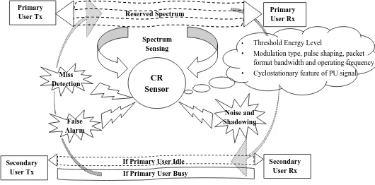
Black spaces:completely occupied by interference and noise. Figure 1 shows CR environment which exhibits primary and sec-ondary user terminal pair, serving CR technology by CR sensor. A CR sensor has prior knowledge about signal threshold energy level, frequency band and cyclostationary features of signal to per-form useful sensing. Sensing perper-formance of CR sensors may get affected due to noise and shadowing which may cause false alarm and missed-detection.
This paper is organized as follows: Section II defines categoriza-tion of signal processing techniques for spectrum sensing. Seccategoriza-tion III presents most popular non-cooperative spectrum sensing tech-niques. In this section spectrum sensing techniques are explained with their relative features and limitations. Cooperative sensing and its types are defined in section IV. Section V gives process flow chart of non cooperative techniques and Section VI concludes this paper.
Miss Detection
False Alarm
Noise and Shadowing
Threshold Energy Level Modulation type, pulse shaping, packet
format bandwidth and operating frequency Cyclostationary feature of PU signal
Spectrum Sensing
CR Sensor
Reserved Spectrum Primary
User Tx
Primary User Rx
Secondary User Tx
Secondary User Rx If Primary User Idle
[image:1.595.325.590.473.604.2]If Primary User Busy
Fig. 2: Cognitive Environment
Fig. 1. Cognitive Environment
2. SPECTRUM SENSING TECHNIQUES
also categorizes non-cooperative and cooperative spectrum sensing techniques.
Cyclostationary feature Detection Matched Filter
Energy Detection
Interference Based Sensing Cooperative
system Non Cooperative
system
Spectrum Sensing
Decentralized Uncoordinated
Centralized Coordinated
[image:2.595.55.300.101.314.2]Decentralized Coordinated
Fig 4: Classification of spectrum sensing techniques [9].
Fig 4: Classification of spectrum sensing techniques [9].
Fig. 2. Classification of spectrum sensing techniques [9].
3. NON-COOPERATIVE SENSING
Non-cooperative sensing techniques need detection of primary user signal by some parameter measurement and filtering. The location of primary user is not known. It is based on following hypotheses
X(t) =
n(t) H0
s(t) +n(t) H1
In above equationH0 denotes absence of primary user and H1
shows its presence.n(t)ands(t)represents noise and primary user massage signal respectively. Popular non-cooperative Sensing tech-niques are:
—Matched filtering. —Energy detection.
—Cyclostationary feature detection.
3.1 Matched Filtering:
Matched filter detection is very accurate and most promising tech-nique for spectrum sensing which maximizes SNR. A matched fil-ter is a linear filfil-ter, based on coherent detection of primary user signal [1], [2], [3], [5]. When we pass the signal from the filter, it passes the useful signal while attenuate the noise signal at the same time. If the desired signal is present, large peak appears at the out-put of the filter, otherwise the signal is not present (only noise is there) [19].
Primary user information e.g., modulation type and order, pulse shaping, packet format bandwidth and operating frequency might be pre-stored in CR memory. The cyclostationary feature detec-tor performs, timing and carrier synchronization as well as channel equalization for received signal[1], [2], [3], [6], [7]. In matched fil-ter operation, received signal is convolved with the filfil-ter impulse
response, which is time shifted and mirror version of reference sig-nal [1], [2], [5],[8]. Optimal detector in stationary Gaussian noise used as matched filter when secondary user has knowledge about information of primary user signal [8], [10]. Matched filter per-forms poorly in case of incomplete or inaccurate information [8], [10]. The operation of matched filter detection is expressed as [1], [2], [3], [8].
Y[n] = +∞ X
k=−∞
h[n−k]z[k]
Wherezis unknown signal and is convolved with theh, the impulse response of matched filter that is matched to the reference signal for maximizing the SNR [1], [2], [3], [8].
BPF
MATCHED FILTER
H0
[image:2.595.322.561.229.281.2]H1
Fig. 5: Matched Filtering [2].
Fig. 3. Matched Filtering [2].
Features:
(1) As Cognitive Radio user knows information of the licensed user signal, matched filter detection requires less detection time due to high processing gain [1], [2], [3], [6], [7], [8]. (2) Matched filtering needs short time to achieve a certain
proba-bility of false alarm or probaproba-bility of missed-detection [2], [7].
Limitations:
There are some limitations of this technique which are:
(1) It requires a prior knowledge of every primary signal [1], [2], [3], [6], [7], [8].
(2) CR needs a dedicated receiver for every type of primary user [1], [3], [6].
(3) Cognitive radio needs receivers for all signal types, the imple-mentation complexity of sensing unit is impractically large [2], [7].
(4) Matched filtering consume large power as various receiver al-gorithms need to be executed for detection [2], [7].
3.2 Energy Detection
Energy detection is the non-coherent detection based sensing tech-nique of CR [6]. The energy detection method is very simple to implement as compared to other techniques, since it does not re-quire the prior knowledge about the structure or format of the pri-mary user signal. The energy detection method calculates energy of the signal of desired frequency band and compares it with a pre-decided threshold energy level [16]. The signal is said to be present at a particular frequency band, if energy of the signal exceeds en-ergy level of the decision threshold [4]. Otherwise processed fre-quency band is expected to be idle and could be accessed by CR.
X(t) =
n(t) H0
s(t) +n(t) H1
H0represents presence of noise only, whileH1represents primary
user signal is present [16], [17].
Squaring Device
( / ) [ ( )] Noise
PreFilter A/D [S(n)]2
[image:3.595.57.297.100.224.2]Threshold comparison
Fig. 6 Energy Detection Process [20] - [25].
Averaging & Summation
Fig. 4. Energy Detection Process [13, 14, 15, 16, 17, 18].
Figure 4 shows block diagram of energy detector. It consist of noise pre-filter, which removes noise from received signal, to be con-verted in digital signal. Square law device squares the digital signal to calculate power within specified window. Averaging and summa-tion is performed to calculate energy over FFT window for durasumma-tion
T[13, 14, 15, 16, 17, 18]. Features:
(1) Energy detection method is popular due to its simplicity, ease of implementation and applicability [16].
(2) It has low computational and implementation cost [16].
Limitations:
There are several limitations of energy detectors that might dimin-ish their simplicity in implementation [23].
(1) Threshold used for primary user detection is highly susceptible to changing noise levels. Presence of any undesired band pos-sessing equal energy level might confuse the energy detector [16].
(2) Energy detector does not differentiate between primary user (PU) signals, noise and interference. So it cannot be beneficial to prevent interference [6].
(3) Energy detector is not useful for direct sequence, frequency hopping signals and spread spectrum signals [6].
(4) When there is heavy fluctuation in signal power so it becomes difficult to differentiate the desired signal [6].
(5) Compared to matched filter detection, energy detection tech-nique requires longer time to achieve desired performance level [16].
3.3 Cyclostationary Feature Detection
Cyclostationary feature detection (CFD) is the two dimensional complex valued spectrum sensing technique. Modulated primary user (PU) signals associated with sine wave carriers, pulse trains, hoping sequences or cyclic prefixes exploit periodicity. The mean and autocorrelation of PU signals exhibit periodicity which is typ-ically introduced in signal format. This periodicity characterizes cyclostationary feature of PU signals [1, 2, 3, 4, 5, 6, 7], [13]. Re-ceiver exploits cyclostationary features of PU signals such as car-rier phase, pulse timing, or direction of arrival. These parameters are used for detection of a random signal in radio environment in presence of other modulated signals and noise [3], [6], [7], [13].
Unlike common analysis as in energy detection and matched filter-ing, stationary random signals are based on autocorrelation func-tions and power spectral density [6]. Cyclostationary signal ex-hibits correlation between widely separated spectral components due to spectral redundancy caused by periodicity [6].
The received signal is assumed to be of following simple form
X(n) =s(n) +w(n)
The cyclic spectral density (CSD) function of a received signal can be calculated as
S(f, α) = ∞ X
τ=−∞
(RαY) (T)e −2jπf T
Where
(RαY) (T) =E
y(n+τ)y(n−τ)e2jπαn
is the cyclic autocorrelation function (CAF),αis the cyclic fre-quency and τ is time delay associated with CAF over time in-tervalT. When the cyclic frequency is equal to the fundamental frequencyfof transmitted signalX(n), the CSD function has its maximum values [2], [3], [6], [7]. Cyclic frequencies are used as features for identifying transmitted PU signals. It can be assumed to be known or they can be extracted [7]. Spectral correlation func-tion is also termed as cyclic spectrum [3], [7]. Signal analysis in cyclic spectrum domain preserves phase and frequency information related to timing parameters in modulated signals. As a result, over-lapping features in the power spectrum density are non-overover-lapping features in the cyclic spectrum [6].
Feature Detect Average
OverT
Correlate
X(f+a)X*(f-a)
Npt FFT A/D
[image:3.595.323.533.378.412.2]X(t)
Fig 7: Implementation of a cyclostationary feature detector [6].
Fig. 5. Implementation of a cyclostationary feature detector
Features:
(1) Cyclostationary feature detection performs better than Energy detection technique in low SNR regions [2], [3], [8].
(2) It is not affected by noise uncertainties. It is robust to noise [2], [3], [8].
(3) Frequency and phase synchronization of signal is not required [8], [12].
Limitations:
(1) CFD requires long observation time, high sampling rate and higher computational complexity [2].
(2) CFD also requires the prior knowledge of primary user signal [2].
(3) There are possibilities of sampling time error.
4. COOPERATIVE SENSING
one CR could work together and can share their sensing informa-tion with one another and cooperatively take decision about spec-trum occupancy, introduces the notion of Cooperative or Collabo-rative or Distributed technique of spectrum sensing [12].
4.1 Decentralized Uncoordinated Techniques
Each CR user performs channel detection independently and does not support or share its information with other CR users [3].
4.2 Centralized Coordinated Techniques:
This technique designates a CR controller which is called fusion center (FC). It is in strong connectivity with its nearby CR users in its range. FC selects desired frequency band and inform all CR in network to perform local sensing. CR user in network detects idle channel or primary user; inform to CR controller which shares this information with all other CR users in network [3], [6], [10].
4.3 Decentralized Coordinated Techniques:
It does not require any CR controller or FC. Each CR user works as FC in network and provides coordination to other CR users [3], [10]. It is also called distributed cooperative sensing technique.
Fig. 6. Cooperative Spectrum Sensing Techniques
Figure 6 shows graphical representation of decentralized and cen-tralized coordinated methods of cooperative spectrum sensing. In coordinated cooperative technique fusion center (FC) is coordinat-ing with 4 CR sensors while in uncoordinated technique all 4 CR sensors are connected with all the other CRs in network without existence of central fusion center.
Features:
(1) Cooperative sensing decreases missed-detection and false alarm probabilities [2].
(2) It solves hidden primary user problem and also decreases sens-ing problems [2].
(3) It provides higher spectrum capacity gains than local sensing [2].
(4) It requires less sensitive detectors, which result in flexibilities, reduced hardware cost and complexities [12].
Limitations:
(1) Combining sensing results of more than one CR users having different sensitivities, is a difficult task [6].
(2) This technique requires a control channel to convey informa-tion among all CR users [6].
5. FLOW CHART
Implementation methodology of matched filtering, energy detec-tion and cyclostadetec-tionary feature detecdetec-tion techniques of spectrum sensing for cognitive radio is shown in Figure7.
Cyclostationary Feature Detection
Input Signal
CAF Calculation
CSD Calculation
Yes No
Calculated CSD= Max (CSD)
PU Signal Present
PU Signal Absent Energy Detection
Yes No
Filter output= Max (SNR)
PU Signal Present
PU Signal Absent Coherent detection
Convolution of input signal and matched filter impulse response
Matched Filtering
Input Signal
Spectrum flow between Primary users
Spectrum Sensing
Input Signal
Energy of Threshold > Energy of Spectrum
Threshold Calculation t
Energy Spectrum of Threshold Threshold Energy Spectrum Energy Spectrum
of Signal Energy Spectrum
Computation
Yes
Frequency Hole is Present No
Frequency Hole is Absent
[image:4.595.93.586.250.495.2]Fig 8: Flow Chart of Spectrum Sensing Methods [4]
Fig. 7. Process Flow Chart of Spectrum Sensing Methods
6. CONCLUSION
7. REFERENCES
[1] Sajjad Ahmad Ghauri, I M Qureshi, M. Farhan Sohail, Sher-azAlam, M. Anas Ashraf, “Spectrum sensing for cognitive ra-dio networks over fading channels,” International Journal of Computer and Electronics Research Vol. 2, Issue 1, February 2013.
[2] Anita Garhwal and Partha Pratim Bhattacharya, “A survey on spectrum sensing techniques in cognitive radio,” Inter-national Journal of Computer Science Communication Net-works, Vol 1(2), 196-206.
[3] V. Stoianovici, V. Popescu, M. Murroni, “A survey on spec-trum sensing techniques for cognitive radio,” Bulletin of the Transilvania University of Brasov Vol. 15 (50) 2008. [4] Anirudh M. Rao, B. R. Karthikeyan, Dipayan mazumdar,
Govind R. Kadambi,“Energy detection technique for spec-trum sensing in cognitive radio,” SASTECH Vol. 9, Issue 1, April 2010.
[5] Mahmood A. Abdulsattar and Zahir A. Hussein, “Energy de-tection technique for Spectrum sensing in cognitive Radio,” International Journal of Computer Networks Communica-tions (IJCNC) Vol.4, No.5, September 2012.
[6] Danijela Cabric, Shridhar Mubaraq Mishra, Robert W. Brodersen Berkeley Wireless Research Center, University of California, Berkeley IEEE Paper, “Implementation issues in spectrum sensing for cognitive radios,” in Proc. the 38th. Asilomar Conference on Signals, Systems and Computers, year 2004, pages 772-776.
[7] Tevfik Yucek and Huseyin Arslan, “A survey of spectrum sensing algorithms for cognitive radio applications,” IEEE communications surveys tutorials, Vol. 11, no. 1, first quarter 2009.
[8] Mansi Subhedar1 and Gajanan Birajdar, “Spectrum sensing techniques in cognitive radio networks: a survey,” Interna-tional Journal of Next-Generation Networks (IJNGN) Vol.3, No.2, June 2011, DOI : 10.5121/ijngn.2011.3203 37. [9] A. Rahim Biswas, Tuncer Can Aysal, Sithamparanathan
Kan-deepan, Dzmitry Kliazovich, Radoslaw Piesiewicz, “Cooper-ative shared spectrum sensing for dynamic cognitive radio networks,” Broadband and Wireless Group, Create-Net In-ternational Research Centre, Trento, Italy, EUWB (FP7-ICT-215669).
[10] Nishant Dev Khaira, Prateek Bhadauria, “Cooperative spec-trum sensing and detection efficiency in cognitive radio net-work,” International Journal of Electronics and Computer Science Engineering ISSN-2277-1956.
[11] Amir Ghasemi, Communications Research Centre Canada and University of Toronto Elvino S. Sousa, University of Toronto, “Spectrum sensing in cognitive radio networks: Re-quirements, Challenges and Design Trade-offs,” IEEE Com-munications Magazine April 2008.
[12] Paul D. Sutton, Member IEEE, Keith E. Nolan, Member IEEE and Linda E. Doyle, Member IEEE, “Cyclostationary signa-tures in practical cognitive radio applications,” IEEE journal on selected areas in communications, Vol. 26, no. 1, January 2008.
[13] Dong-Chan Oh and Yong-Hwan Lee, “Energy detection based spectrum sensing for sensing error minimization in cog-nitive radio networks,” International Journal of Communica-tion Networks and InformaCommunica-tion Security (IJCNIS) Vol. 1, No. 1, April 2009.
[14] Komal Arora, Ankush Kansal, Kulbir Singh, “Comparison of energy detection based spectrum sensing methods over fad-ing channels in cognitive radio signal processfad-ing,” An Inter-national Journal (SPIJ), Vol (5) : Issue (2) : 2011 44. [15] Md. Shamim Hossain, Md. Ibrahim Abdullah, Mohammad
Alamgir Hossain, “Energy detection performance of spec-trum sensing in cognitive radio,” I.J. Information Technol-ogy and Computer Science, 2012, 11, 11-17 Published Online October 2012 in MECS (http://www.mecs-press.org/) DOI: 10.5815/ijitcs.2012.11.02.
[16] Miguel Lpez-Bentez and Fernando Casadevall, “Improved energy detection spectrum sensing for cognitive radio,” Thsis paper published in IET communication publication, IET Communications(2012), 6(8):785.
[17] Saqib Saleem and Khurram Shahzad, “Performance evalua-tion of energy detecevalua-tion based spectrum sensing technique for wireless channel,” International journal of multidisciplinary sciences and engineering, Vol. 3, no. 5, may 2012.
[18] Zhiqiang Bao, Bin Wu, Pin-Han Ho and Xiang Ling, “Adap-tive threshold control for energy detection based spectrum sensing in cognitive radio networks,” This full text paper was peer reviewed at the direction of IEEE Communications Soci-ety subject matter experts for publication in the IEEE Globe-com 2011 proceedings.
![Fig 4: Classification of spectrum sensing techniques [9].](https://thumb-us.123doks.com/thumbv2/123dok_us/8044510.772305/2.595.55.300.101.314/fig-classification-of-spectrum-sensing-techniques.webp)
![Fig. 6 Energy Detection Process [20] - [25].](https://thumb-us.123doks.com/thumbv2/123dok_us/8044510.772305/3.595.57.297.100.224/fig-energy-detection-process.webp)
![Fig. 7.Process Flow Chart of Spectrum Sensing MethodsFig 8: Flow Chart of Spectrum Sensing Methods[4]](https://thumb-us.123doks.com/thumbv2/123dok_us/8044510.772305/4.595.93.586.250.495/process-chart-spectrum-sensing-methodsfig-spectrum-sensing-methods.webp)
