http://dx.doi.org/10.4236/jpee.2014.24088
Study on Decision Method of Neutral Point
Grounding Mode for Medium-Voltage
Distribution Network
Hengyong Liu1, Xiaofu Xiong2, Jinxin Ouyang2, Xiufen Gong2, Yinghua Xie1, Jing Li1 1Shenzhen Power Supply Co. Ltd., Shenzhen, China
2State Key Laboratory of Power Transmission Equipments & System Security and New Technology,
College of Electrical Engineering, Chongqing University, Chongqing, China Email: [email protected]
Received February 2014
Abstract
The neutral grounding mode of medium-voltage distribution network decides the reliability, overvoltage, relay protection and electrical safety. Therefore, a comprehensive consideration of the reliability, safety and economy is particularly important for the decision of neutral grounding mode. This paper proposes a new decision method of neutral point grounding mode for medium- voltage distribution network. The objective function is constructed for the decision according the life cycle cost. The reliability of the neutral point grounding mode is taken into account through treating the outage cost as an operating cost. The safety condition of the neutral point grounding mode is preserved as the constraint condition of decision models, so the decision method can generate the most economical and reliable scheme of neutral point grounding mode within a safe limit. The example is used to verify the feasibility and effectiveness of the decision method.
Keywords
Distribution Network; Neutral Grounding Mode; Reliability; Decision Method; Objective Function
1. Introduction
the power frequency overvoltage is low, the insulation level of transmission line and equipment requirements and the total costs are lower than the arc suppression coil grounding mode, the single-phase grounding fault de-tection has high sensitivity, but also because of the large grounding fault current, the potential rise higher, ad-verse to the personal and equipment safety, and the protection clear the fault rapidly, cause the power supply in-termittent [4].
To choose a reasonable, safe and efficient neutral grounding mode of the power grid can guarantee the relia-bility and safety of the power network and also can avoid causing large economic investment, which has great significance for the efficient operation of power system. Large amounts of references have researched on the in-fluence of different neutral grounding mode. References [5]-[7] according to the capacitive current magnitude of Suzhou, Wuhan and Guizhou area, put forward the neutral point grounding mode suitable for them respectively. References [8]-[10] focus on the analysis of neutral grounding via low resistance and grounding by arc suppres-sion coil the advantages and disadvantages of the two methods, and points out that the small resistance groun-ding mode in power supply reliability depends on the network structure and the automation level, but the arc suppression coil grounding mode will have technical and economic advantages through the optimization of au-tomatic tuning device.
Nowadays, a common simple method to realize the selection of the neutral grounding mode of medium- vol-tage distribution network mainly through the influence comparison between them, there is still lack of quantita-tive neutral point grounding mode decision method. The reference [11] using experts scoring method to arrive the neutral point grounding mode choice factors, weight the relative value of the factors in different neutral grounding modes, choose the grounding mode which has the maximum weighted total value. The reference [12] according to the influence factors of neutral point grounding mode, establishes the corresponding membership function, through fuzzy theory to build the neutral point grounding mode decision method. The reference [13] [14] by comparing the fault tripping rate relative superiority degree of different neutral point grounding mode, to evaluate the neutral grounding mode.
The lack of neutral point grounding mode decision method leads to great impact on power system planning and operation. This paper presents a comprehensive neutral grounding modes for distribution network, which integrates the influence of reliability, safety and economy, combine the reliability evaluation of distribution network under various neutral grounding modes and the economic operation cost which included in the safety factors together, calculate life cycle cost of the distribution network under various neutral grounding modes and combining the reliability index as constraint conditions to achieve the neutral grounding mode decision.
2. Neutral Point Grounding Mode Decision Method
The decision method makes use of the optimization idea [15] [16], lets economic index optimal as objective function, the reliability index as constraint conditions to establish the neutral point grounding mode decision model. As the objective function:
minW G= +X+ +K F (1) Constraint conditions:
max
min max
max
1 j
j j
j j j
ij ij L
j j jk
k ASAI A CAIDI C
P P
U U U
I I
P q P
Γ
Γ
= ≥
≤
≤
≤ ≤
≤
= +
∑
(2)
availability index value for an actual network required, CΓ stands for the customer average interruption dura-tion index value for an actual network required; Pj and Pjmax respectively to the transmission power and the maximum allowable power for the load point j; Ujmin and Ujmax stands for the maximum and minimum limit voltage value for the load point j; qj stands for the load value of the load point j; Lj stands for the total load
point number; Pjk stands for the section line k’s power which supplied by the load point j; Iij and Iijmax stands for the line current and the maximum allowable current.
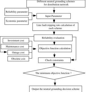
The decision method considers the influence about the reliability of distribution network with different neutral grounding mode, using the reliability parameter to evaluate the distribution network reliability for different neu-tral grounding mode. Transfer the expected energy not supplied index to the outage cost, as an objective func-tion which takes the other reliability factors into account, makes the average supply availability index and cus-tomer average interruption duration index as the reliability constraints. The process is shown in Figure 1.
3. Neutral Point Grounding Mode Decision Objective Function
3.1. Equipment Input Cost G
The equipment input cost which considering the safety factors includes the cost of the initial investment in equipment and operating added facilities investment:
1
(1 ) +
(1 ) 1
i n m
i i n
i
k k
G p a
k
=
+
=
+ −
∑
(3)In the formula, m stands for the total number of investment items; ni stands for the useful life of investment;
k stands for the annual interest rate; pi stands for the initial investment cost of investment; ai stands for the
[image:3.595.148.451.378.701.2]required operating cost for each investment.
Figure 1. Neutral grounding mode decision process. Economic parameter
Reliability parameter
Input Parameter
Reliability evaluation
The minimum objective function ?
Output the neutral grounding decision scheme Investment cost
Outage cost
Obsolete cost
Check constraints Objective function calculation Line fault tripping rate calculation of
each scheme
Different neutral grounding schemes for distribution network
According to the different neutral point grounding scheme, the initial investment which considering the safety factors mainly include the purchase cost of neutral point grounding device, relay protection device, insulation equipment, automation equipment and line selection device, also contain the support of the engineering ex-penses and other exex-penses. Among them, the relay protection device, insulation equipment and automation equipment investment are all closely related with the safety factors, such as the use of expensive insulated cable can reduce the risk of electric shock.
The operation investment which considering the safety factors mainly refers to the additional safety protection facilities investment. Including the installation of security fence, cable channel and sidewalk distance in the planning and construction investment to guarantee personal safety.
3.2. Maintenance Cost X
Maintenance cost includes fault repair cost incurred, and regular inspection cost:
1 n
i i
X J
=
=
∑
(4)In the formula, n stands for general items of the annual maintenance task; Ji stands for the maintenance
cost for task i, including the cost of materials and labour cost.
3.3. Outage Cost K
According to the expected energy not supplied index, consider the electricity production ratio and the reliability penalty coefficient [18], can calculate the outage cost:
K = ×α ENS c× (5) In the formula, ENS stands for expected energy not supplied of each neutral point grounding mode , which can be obtained from reliability evaluation of different neutral point grounding mode; α stands for the relia-bility penalty coefficient of anunal outage loss, usually value for 1 - 2; c stands for the area’s electricity pro-duction ratio, refers to the output value creation of the region within a year(expressed in monetary form) and the consumption of electricity ratio:
i i
c=GDP EC (6) In the formula, GDPi stands for the gross domestic product in price of the region; ECi stands for the total
electricity consumption a year of the region.
3.4. Obsolete Cost F
1
(1 )
(1 ) 1
i n p
i n i
k k
F Q
k
=
+
=
+ −
∑
(7)Where p stands for the total number of equipments; Qi stands for the obsolete cost of equipment i; ni
stands for the service life of equipment i; k stands for the annual interest rate.
4. Reliability Index
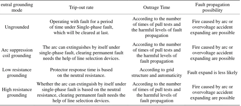
Under single-phase grounding fault, the impacts tabulated as the following Table 1, on trip-out rate, outage time and fault propagation vary according to the neutral grounding mode [19].
In the following analysis, λ is failure rate of transmission line i, the rate of single-phase grounding fault is η, transient fault is δ , the possibility of overvoltage accident extension is e1, the possibility of fire accident is
2
Table 1. Effects of different neutral grounding mode for distribution network reliability.
eutral grounding
mode Trip-out rate Outrage Time
Fault propagation possibility
Ungrounded
Operating with fault for a period of time under Single-phase fault,
which will be cleared at last.
According to the number of times of pull tests and the harmful levels of fault
propagation
Fire caused by arc or overvoltage accident expanding are possible
Arc suppression coil grounding
The arc can extinguishes by itself under single-phase fault, clearing permanent fault
needs the help of line selection devices.
According to the number of times of pull tests and the harmful levels of
fault propagation
Fire caused by arc or overvoltage accident expanding are possible
Low resistance grounding
Protector response time is based on the neutral resistance.
According to grid
structure and automaticity Fault expand is less likely
High resistance grounding
Whether the arc can extinguish by itself under single-phase fault is based on the neutral resistance, clearing permanent fault needs the
help of line selection devices.
According to the number of times of pull tests and the harmful levels of
fault propagation
Fire caused by arc or overvoltage accident expanding are possible
4.1. Tripping Rate in Ungrounded Network
When line i failure, the tripping rate is
(
) (
+ 1) (
=)
ii
P =λη 1−δ λ −η λ 1−ηδ (8) The rate of line i failure but the fault extend to cause the normal line j tripping is
(
)(
1 2 1 2)
ij
P =λη 1−δ e + −e e e (9)
4.2. Tripping Rate in Arc Suppression Coil Grounding Network
After line i failure, the tripping rate is
(
1)
(
1)
(
1)
(
1)
ii
P =ληδ −α +λη −δ +λ −η =λ −ηδα (10) The rate of line i failure but the fault extend to cause the normal line j tripping is
(
1)
(
1) (
1 2 1 2)
ij
P =ληδ −α +λη −δ e + −e e e (11)
4.3. Tripping Rate of Low Resistance Grounding Network
After line i failure, the tripping rate is
(
1)(
1)
(
1)(
1) (
+ 1)
(
1 +)
ii
P =ληδ −β −θ +λη −δ −β λ −η =λ −ηβ ηδθ ηβδθ− (12) The rate of line i failure but the fault extend to cause the normal line j tripping is
(
1)
=ij
P =ληδβ λη+ −δ β ληβ (13)
4.4. Tripping Rate of High Resistance Grounding Network
After line i failure, the tripping rate is
(
1)(
)
(
1)(
)
(
1)
(
1) (
+ 1)
ii
P =ληδ −σ 1−ς +λη −δ 1−ς +λ −η =ληδσ −ς λ −ςη (14) The rate of line i failure but the fault extend to cause the normal line j tripping is
(
1)
(
1) (
1 2 1 2)
ij
P =ληδ −σ +λη −δ ς e + −e e e (15) Tripping rate of transmission line i P i equals to the sum of tripping rate when fault occurs on itself and
trip-ping rate when fault occurs on other lines but extends to line i.
availability index), CAIDI (customer average interruption duration index), and ENS (energy not supplied) can be calculated [20], illustrated as follow:
8760
8760
m m
i i i
i i
m
i i
N U N
ASAI
N
− =
∑
∑
∑
(16)m SLi i i m SLi i i U N CAIDI f N =
∑
∑
(17)m
ai SLi i
ENS=
∑
P U (18) Where, m denotes the number of load point, N i is the number of customer connecting to load point i , USLiis the outrage time of load point i in one year, fSLi is the outrage rate of load point i, P ai isaverage load of
load point i.
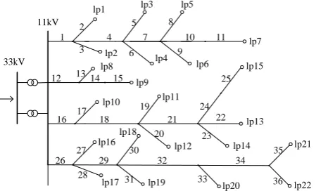
[image:6.595.239.359.116.257.2] [image:6.595.189.414.461.597.2]5. Example
Figure 2 is a RBTS Bus 2 system, which is composed by 2 main transformers, 4 transmission feeder lines, 36 lines and 22 load points with distribution transformers, and it is a medium voltage system of 33/11 kV [21]. All the transmission line in the system are cables [22], and the parameters are: λ=0.04, r = 8,η = 0.8, δ = 0.55, α
= 0.9, β = 0.01, ζ = 0.2, e1 = e2 = 0.1, m = 2, ω = 0.5, θ =0.5. Assuming that the reliability indexes of this net-work are: AΓ =99.96%, CΓ =3.5h. Service life of each device is n=20 years, annual rate k=5%, elec-tricity production rate c=5.27 yuan/kWh, penalty coefficient α =1.5.
The results of reliability indexes calculation under different neutral grounding mode are tabulated in Table 2. As we can see that under low resistance grounding mode, there is higher power supply availability, shorter cus-tomer interruption time and less power not supplied than that of other neutral grounding modes; the counterparts in neutral isolated system, resonance grounding system and high resistance grounding system not very much.
[image:6.595.155.441.642.720.2]Figure 2. RBTS Bus 2 system diagram.
Table 2. Reliability index.
Neutral grounding mode ASAI CAIDI ENS (MW) Arc suppression coil grounding 99.9633% 3.2171 40.9126
Low resistance grounding 99.9707% 2.5679 26.4863 Ungrounded 99.9614% 3.3819 41.1909 High resistance grounding 99.9627% 3.2662 38.3552
33kV 11kV
1 4
2
lp1 lp3 lp5
lp7 lp2 lp4 lp6 lp8 lp9 lp10 lp11 lp15 lp13 lp12 lp14 lp16 lp17 lp18 lp19 lp20 lp21 lp22 3 5 6 8 9 10 7 11
12 13 14 15
Based on actual operation data and Electric power construction engineering budget quota, the items of in-vestment costs by different neutral grounding methods can be obtained, as listed in Table 3, total costs are in Table 4.
Costs of repair in one year of different neutral grounding system are tabulated in Table 5 based on the statistic material. Equivalent annual obsolescence costs are also listed in Table 5 based on practical operation expe-rience.
In accordance with the power not supplied in different neutral grounding system, interruption cost of one year can be obtained, as shown in Table 6.
Based on decision-making progression and objective functions in Figure 2 under different neutral grounding conditions, the results can be obtained, as Table 7 shows.
The objective function is bigger under both conditions of resonance grounding and high resistance grounding than under conditions of low resistance grounding and isolated neutral system. Under the limit of reliability level, power system with low resistance grounding method has the highest level of reliability, and also its objective function is the optimal function, in terms to a network as Figure 2, low resistance grounding method is recom-mended.
Table 3. Equipment investment costs.
Scheme (ten thousand yuan)
Neutral grounding device
Relay protector
Insulation device
Automatic device
Arc suppression coil grounding
Initiative investment
Acquisition 27 22.5 23.6 49
Installation 0.1 0.05 0.9 1.04
Other expense 0 0 0.5 0
Operation cost 5
Low resistance grounding
Initiative investment
Acquisition 11 24.5 20.6 49
Installation 0.1 0.05 0.6 1.04
Other expense 0 0 0.2 0
Operation cost 9
Ungrounded
Initiative investment
Acquisition 0 10 26.6 35
Installation 0 0.02 1.1 0.7
Other expense 0 0 0.7 0
Operation cost 2
High resistance grounding
Initiative investment
Acquisition 16 23.5 24.6 41
Installation 0.11 0.05 1 1.04
Other expense 0 0 0.6 0
Operation cost 4
Table 4. Annual investment cost.
Scheme (Unit: Ten thousand yuan) P a Annual cost G
Ungrounded 73.36 2 11.50
Arc suppression coil grounding 123.79 5 21.03
High resistance grounding 106.9 7 20.84
Table 5. Annual repair cost and obsolete cost.
Scheme( Unit: Ten thousand yuan) repair cost X Obsolete cost F
Ungrounded 3.70 −1.06
Arc suppression coil grounding 4.20 −2.45
High resistance grounding 4.50 −2.21
Low resistance grounding 4.90 −1.94
Table 6. Annual outage cost.
Scheme Power not supplied (MW) Annual cost K (Ten thousand yuan)
Ungrounded 41.1909 32.56
Arc suppression coil grounding 40.9126 32.34
High resistance grounding 38.3552 30.32
Low resistance grounding 26.4863 20.94
Table 7. Annual total economic cost.
Cost
Sheme G X K F W
Ungrounded 11.50 3.70 32.56 −1.06 46.70
Arc suppression coil grounding 21.03 4.20 32.34 −2.45 55.12
High resistance grounding 20.84 4.50 30.32 −2.21 53.45
Low resistance grounding 22.79 4.90 20.94 −2.51 46.12
6. Conclusion
As the development of power system, the neutral grounding mode diversified, to look for a method which can better fit the reliability, security and economy demands is significant for the planning and efficient operation of power system. Currently, decision about power system neutral grounding method lacks quantitative assessment, consequently synthetic decision is impeded, whereas, this paper proposed a decision method considering relia-bility indexes, and minimal life cycle cost based on reliarelia-bility factors, via RBTS Bus 2 system the method is tes-tified availably. This method synthesizes reliability security and economy demands, and can assure high econ-omy and reliability, it provides effective computing method for neutral grounding design and planning of distri-bution network.
References
[1] Ping, S.-X. and Zhou, Y.-F. (2010) Power System Neutral Grounding Mode and Operation Analysis. China Electric Power Press, Beijing, 118-119.
[2] Su, J.-F. (2013) Research of Neutral Grounding Modes in Power Distribution Network. Power System Protection and Control, 41, 143-147.
[3] Guo, Q.-T. and Wu, T. (2010) Survey of the Methods to Select Fault Line in Neutral Point Ineffectively Grounded Power System. Power System Protection and Control, 38, 146-152.
[4] Fu, X.-Q., Xu, L.-Z. and Zhao, B.-L. (2010) Discussion on the Technology and Application of 10 kV Distribution Network Neutral Grounding through Small Resistance. Power System Protection and Control, 38, 227-230.
[5] Dai, K.-M. (2000) Analysis on Neutral Grounding of Distribution System. Power System Technology, 24, 52-55. [6] He, Z.-F. and Liu, P. (2002) Research of Neutral Point Grounding Modes in MV Distribution Network. Electric Power
[7] Zhou, Y., Zhao, L.-J. and Kang, P. (2006) Neutral Grounding Mode of Urban Distribution Networks in Guizhou Prov-ince. Power System Technology, 30, 61-64.
[8] Zhao, R., Tan, W.-P. and Yang, Y.-H. (2007) Analysis of Neutral Grounding Operation Modes for Distribution Net-work. RELAY, 35, 22-26.
[9] Lin, Z.-C. (2004) The Selection and Application of Neutral Grounding Method of MV Network. High Voltage Engi-neering, 30, 60-64.
[10] Liu, M.-Y. (2004) Selection of Neutral Grounding Modes in Power Distribution Network. Power System Technology,
28, 86-89.
[11] Fu, Y.-S., Wang, Z.-G. and Kuang, S. (2006) Medium-Voltage Grid Grounding Comprehensive Selection Method.
Power System Technology, 30, 101-106.
[12] Liu, Y., Nie, Y.-X. and Peng, X.-G. (2010) Application Research on the Mode Selection of Neutral Grounding with Fuzzy Reasoning Method. Power System Protection and Control, 38, 32-36.
[13] Cao, Z.-C., He, J.-S. and Yang, X.-C. (2007) Interval Analysis about Influence on Reliability of Power Distribution Lines with Various Grounded Neutrals. Guangxi Power, 5-7.
[14] Cao, Z.-C.,Wang, W.-L.,Yang, X.-C., et al. (2007) Decision Arithmetic of Neutral Grounding Mode Based on Interval Multiattribute Weighted Grey Target Theory. Guangxi Power, 1-5.
[15] Ramirez-Rosado, I.J. and Dominguez-Navarro, J.A. (2006) New Multi-Objective Tabu Search Algorithm for Fuzzy Optimal Planning of Power Distribution Systems. IEEE Transactions on Power Systems, 21, 224-233.
http://dx.doi.org/10.1109/TPWRS.2005.860946
[16] Chen, D.-W. and Zhang, P.-M. (2011) Virtual Prototype Optimal Design of Intelligent AC Contactors Based on Artifi-cial Fish-Swarm Algorithm. Transactions of China Electrotechnical Society, 26, 101-106.
[17] Su, H.-F., Zhang, J.-H., Liang, Z.-R., et al. (2012) Substation LCC Planning Based on Refined Mean Clustering Ran-dom Particle Swarm Algorithm. Transactions of China Electrotechnical Society, 27, 209-214.
[18] Luo, X.-C., Li, L. and Wei, Z.-L. (2011) Applications of Life Cycle Cost Theory in Decision-Making of Investment for Distribution Transformers Renovation. Power System Technology, 35, 207-210.
[19] Li, B. and Shu, H.-C. (2012) Applications of Life Cycle Cost Theory in Decision-Making of Investment for Distribu-tion Transformers RenovaDistribu-tion. Transactions of China Electrotechnical Society, 27, 183-190.
[20] Xu, J.-Z. and Li, Y. (2007) Reliability Assessment of Complex Distribution System Using GO Method. Transactions of China Electrotechnical Society, 22, 149-153.
[21] Billinton, R., Kumar, S., Goel, L., et al. (1989) A Reliability Test System for Educational Purposes-Basic Data. IEEE Transactions on Power Apparatus and System, 4, 1238-1244. http://dx.doi.org/10.1109/59.32623