2018 2nd International Conference on Modeling, Simulation and Optimization Technologies and Applications (MSOTA 2018) ISBN: 978-1-60595-594-0
RFID Tag Group Performance Detection Based on Optoelectronic
Sensing Technology
Guang-jun ZHOU
1, Xiao-lei YU
1,*, Meng-jie LIU
2and Dong-sheng LU
21National Quality Supervision and Testing Center for RFID Product, Nanjing 210029, China
2College of Science, Nanjing University of Aeronautics and Astronautics, Nanjing 210016, China
*Corresponding author
Keywords: RFID tag group, Performance testing, Reading distance, Optoelectronic detection
system.
Abstract. With the rapid development of the industry in internet of things (IOT), the application of RFID multi-tag has become increasingly widespread. This paper proposed and designed a RFID tag group performance photoelectric detection system by combining RFID detection technology with photoelectric sensing technology, and verified the feasibility of the designed platform through experiments and comparative analysis of test results such as the maximum reading distance of RFID tags. This article provides a new approach for the research and application of RFID based IOT system.
Introduction
Radio frequency identification (RFID) is a non-contact automatic recognition technology that uses radio signals to identify specific targets. It has the advantages of fast reading speed, far reading distance, recognition of multi targets and high-speed moving objects. The general external impression of RFID is mainly in the fields of warehousing, logistics and transportation management. However, the available fields of RFID software are very wide. RFID plays a fundamental role in so-called digital factories or 4.0 industries, aiming to improve the automation of industrial processes. In addition, RFID has been found to be very helpful in improving the tracking of patients, medicines and medical assets, and the digitization of these operations improves their efficiency and safety. [1].
So far, RFID technology has been relatively mature and has made great achievements in products. Some research has been carried out around RFID and application technology. Yu proposed the semi-physical simulation technology and the internet of things (IOT) application system, and carried out dynamic testing and semi-physical verification of typical Internet of things systems such as RFID system, vehicle-borne internet system, and two-dimensional bar code recognition system [2]. Colella provides a measuring platform for the performance analysis of UHF Passive RFID tags, which can effectively guarantee high performance [3]. Zhang proposed an algorithm based on Bayesian filter and variable power radio frequency identification (RFID) model for locating passive ultra-high frequency (UHF) RFID tags in complex environments, such as distribution centers/warehouses and relocation [4]. Lee use P2P network based on RFID sensor system can play an important role in a pervasive environment [5]. However, most of recent research is mainly focused on single tag and its performance static testing. At present, there is still a lack of RFID effective detection platform for dynamic testing of key parameters such as tags group reading range, and the results are rarely [6].
System Principle
The typical RFID system consists of three parts: radio frequency front-end, middleware and background computer information management system. The radio frequency front end of the RFID system consists of at least two parts of the electronic tag and reader, in which the reader mainly accepts the control instructions from the background and is responsible for the two-way information transmission with the electronic tag, while the electronic tag is a data carrier, responding to the reader's request and feedback information. RFID middleware is located between RFID system and application system. It is responsible for data transmission between RFID system and application system. It solves the problems of reliability, security and data format conversion of RFID data. The receiving antenna of the RFID system receives the carrier signal from the tag and transmits it to the RFID reader through the antenna regulator. The reader reads and demodulates the received signals and sends them to the background computer control system. The computer control system judges the validity of the electronic tag according to the logic operation, makes corresponding processing and control according to different settings, and sends out command signal to control the action of the actuator. The monitoring points are connected by computer communication network to form the master control information platform, and different software is designed according to different projects to complete the functions to be realized.
Photoelectric Detection System
System Design and Structure
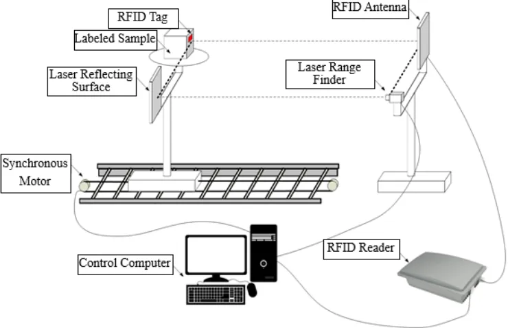
[image:2.595.113.483.525.764.2]According to the working principle and characteristics of RFID system, combined with the dynamic measurement needs of tags, the photoelectric detection system for RFID performance designed in this paper is shown in Figure 1. The system is mainly composed of RFID antenna, RFID reader, laser range finder, laser reflecting surface, labeled sample, synchronous motor, control computer and so on. The synchronous motor controls the operation of the track. The laser reflecting surface needs to be in the same line as the laser rangefinder, and the laser reflecting surface needs to be in the same plane as the sample tray. The computer connected the synchronous motor, the laser rangefinder and the RFID reader. When the synchronous motor starts to work, the sample tray moves on the track. When the RFID antenna detects the RFID tag signal, the laser rangefinder measures the reading distance by the distance from the laser emitted to the laser reflecting surface, and the result is displayed on the computer screen.
Measurement Principle
Before the system starts to work, the initial parameters needed for the experiment need to be set up on the computer, such as power and sample moving speed and so on. The RFID tag is attached to the sample, and the sample and laser reflecting surface need to be in the same plane. When the system begins to work, the sample is driven by the synchronous motor, and it moves along the track at the set speed. When the electronic tag enters the read area of the RFID antenna, the reader will read the electronic tag and send the signal to the control computer, and then the laser rangefinder is notified by the control computer for the range finder. At this time the laser range finder begins to work, measuring the distance between the laser reflector and the laser rangefinder. The distance is the reading distance of the RFID tag, and the acquired distance is fed back to the control computer, and the measurement is completed at this time. When the number of tags in the experiment changes, it is necessary to reset the initial parameters to ensure the accuracy of the experiment.
Dynamic Measurement
Measurement Process
In the RFID performance detection system designed in this paper, Larid A9028 antenna is selected as the RFID antenna. The antenna is a far-field antenna with a maximum reading distance of 15m. The RFID reader selects the Speedway Revolution R420 reader of Impinj Company of America. The laser ranging sensor selects Wenglor's X1TA101MHT88 laser ranging sensor. The detection range of the sensor is 15m and the precision is 2 mm. The data carrier protocol is ISO/IEC 18000-6.
First, the initial parameters need to be set and determined. Second, the tag needed for the experiment is selected. In this experiment, five tags are needed, labeled as tags 1 to tag 5, in which tags 1 to tag 4 are similar in performance, and both have obvious performance differences with tag 5. We select two from the five tags as a tags group, and respectively measure the reading distance of single and multiple tags respectively. Finally, all the experimental data are recorded and the data are analyzed. Because the tags selected in the experiment have linear polarized antennas, when the tag is placed in different positions, the reading distance will also change. Therefore, the polarization direction of tags needs to be considered. In order to exclude the influence of tag polarization direction and tag distribution distance, the tags in the same direction and equal distance.
Feasibility Verification
Single Tag Read Distance Measurement
A schematic diagram of a single tag test system is shown in Figure 2. Before the performance test of the RFID tag, the initial parameters are set as follows: the ambient temperature is 25°C, the antenna transmitting power is 20dBm, the antenna receiving sensitivity is -70dBm, the relative height 0m of the optical lifting platform, the range sensor precision is 2 um, and the tag motion speed is 20m/min. Then set the "tag number" set to 1, confirm the parameters after the measurement, select a tag attached to the template surface and make the tag geometry center and the RFID antenna high, start the motor transmission module, so that the RFID tag moves from the distance to the antenna direction. When the RFID reader is successfully identified to a single tag, the photoelectric sensing module begins to work synchronously. The result of the laser rangefinder is a single tag read distance and is displayed on the display screen, as shown in Table 1.
Table 1. Single Tag Measurement Distance Result.
Tag NO
Times 1 2 3 4 5
1 3.9390m 3.7680m 3.9280m 3.9600m 8.2310m
2 3.3580m 3.9070m 3.7580m 3.9510m 8.8210m
3 3.9360m 3.8940m 3.9280m 3.9350m 9.0430m
4 3.7660m 3.3970m 3.7460m 3.9590m 8.6240m
5 3.7880m 3.6990m 3.7410m 3.7580m 8.4250m
Average 3.7574m 3.7330m 3.8202m 3.9126m 8.6288m
Multi-tag Read Distance Measurement
A schematic diagram of tags group measurement system is shown in Figure 3, which consists of laser range finder, display module and RFID antenna.
Before the test platform is used to measure the performance of the RFID tag, the initial parameters are set as follows: the ambient temperature is 25℃, the transmitting power of the antenna is 20dBm, the antenna receiving sensitivity is -70dBm, the optical lifting platform is relatively high 0m, the range sensor precision is 2 um, and the speed of the tag is 20m/min. Then, the number of "tag" is set to 2. After confirming the parameters, the tags of different combinations are attached to the sample surface and the tag geometry center and the RFID antenna are high. The tags group is pasted in the same direction and equidistance way, so as to eliminate the influence of the polarization direction of the tag, the spacing of the tags and so on, and start the transmission of the motor. The module is transported to move the RFID tag from the far direction to the antenna. When the RFID reader successfully identifies all tags, the photoelectric sensing module begins to work synchronously. The result of the laser rangefinder is the tags group reading distance and is displayed on the display screen, as shown in Table 2.
[image:4.595.68.279.436.591.2] [image:4.595.244.516.436.596.2]
Figure 2. Single tag measurement system. Figure 3. Tag group measurement system.
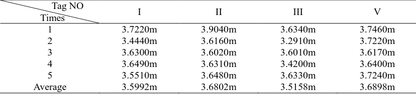
Table 2. Multi-tag measurement distance result.
Tag NO
Times I II III V
1 3.7220m 3.9040m 3.6340m 3.7460m
2 3.4440m 3.6160m 3.2910m 3.7220m
3 3.6300m 3.6020m 3.6010m 3.6170m
4 3.6490m 3.6310m 3.4200m 3.6400m
5 3.5510m 3.6480m 3.6330m 3.7240m
Average 3.5992m 3.6802m 3.5158m 3.6898m
[image:4.595.90.504.630.724.2]slightly smaller than that of a single tag in the tags group. When a tags group is composed of tags with similar performance, such as tags group I and tags group II, there is little difference between the reading distance of the tags group and that of a single tag. When the tags group is composed of tags with different performance, such as tags group III and tags group V, the tags group's reading distance is close to that of the tags with poor performance in the tags group. This fully shows that the performance of tags group is determined by poor performance tags in tags group, which conforms to the general rule.
The measurement results show that the designed system effectively realizes the measurement of RFID tags group parameters. The results show that the designed system is feasible for RFID tags group performance parameters detection.
Summary
In view of the shortcomings of the current RFID tag group performance detection, this paper designs a RFID tags group performance detection system based on photoelectric sensing, which could measure and analyze the reading distance of the single tag and multi-tag of the RFID through the corresponding experiments. The RFID tags group performance detection system designed in this paper can effectively detect the reading distance of single tag, the reading distance and the literacy rate of multi tags. The system and method proposed in this paper are of great significance to the study of the reading distance of RFID tag and the multi-tag collision of RFID systems.
Acknowledgment
The work is supported by the National Natural Science Foundation of China under Grant NO.61771240, China Postdoctoral Science Foundation under Grant NO.2015M580422 & NO.2016T90452, Six Talent Peaks Project in Jiangsu Province under Grant NO.XYDXX-058, Science and Technology Project of AQSIQ under Grant NO.2017QK117 & NO.KJ175943 as well as the 352 Talent Project of Jiangsu Bureau of Quality and Technical Supervision.
References
[1] Alvarez Lopez Y, Franssen J, Alvarez Narciandi G, et al.RFID technology for management and tracking: e-Health applications.Sensors, 2018, 18(8).
[2] Yu XL, Wang DH, Zhao ZM. Semi-physical verification technology for dynamic performance of internet of things system. Science Press, Beijing and Springer Nature Singapore Pte Ltd, https://doi.org/10.1007/978-981-13-1759-0, 2018.
[3] Colella R, Catarinucci L, Coppola P, et al. Measurement platform for electromagnetic characterization and performance evaluation of UHF RFID tags. IEEE Transactions on Instrumentation & Measurement, 2016, 65(4): 905-914.
[4] Zhang J, Lyu YB, Patton J, et al.BFVP: a probabilistic UHF RFID tag localization algorithm using Bayesian filter and a variable power RFID model. IEEE Transactions on Industrial Electronics, 2018, 65(10): 8250-8529.
[5] Lee Y, Cho J. RFID-based sensing system for context information management using P2P network architecture. Peer-To-Peer Networking and Applications, 2018, 11(6): 1197-1205.