View
Prepared for Dr. Paul Hess, ONR Code 331
Matthew Collette (U of M), Robert Sielski (Consultant)
MSDL Report Number: 2016-003
Date: March 13th, 2017
Abstract: Conducting fluid-structure interaction (FSI) experiments and simulations is a critical naval engineering capability for the U.S. Navy. However, past workshops on FSI problems have revealed that the FSI community is split into different technical groups. Fur-thermore, the user communities — practicing engineers and platform teams — are also separate. In July 2016, a cross-community working group of almost 60 people was convened at the University of Michigan Ann Arbor. This working group explored current and an-ticipated use cases for FSI simulation. Research challenges were also discussed. From this cross-community discussion, it was also possible to start to develop a common taxonomy of FSI problems and modeling approaches. This report documents the state of practice revealed by this working group.
Marine Structures Design Lab
Department of Naval Architecture and Marine Engineering University of Michigan, 2600 Draper Drive
Ann Arbor, Michigan 48109 msdl.engin.umich.edu
Fluid Structure Interaction: A Community View
Contents
1 Executive Summary 3
1.1 Scope and Purpose . . . 3
1.2 Major Activities . . . 3
1.3 Discussion . . . 4
2 Introduction 5 2.1 State-of-the-Art in Fluid Simulations . . . 6
2.2 State-of-the-Art in Structural Simulations . . . 8
2.3 State-of-the-Art in Coupling Between Fluids and Structures . . . 12
3 Summary of Use Cases and Future Needs 15 3.1 Use Cases . . . 15
3.2 Future Needs . . . 19
4 Taxonomy and Scope of Application 20 4.1 Taxonomy . . . 21
4.1.1 Description of FSI Problems . . . 21
4.1.2 Description of Numerical FSI Solution Methods . . . 22
4.2 Scope of Application . . . 27
5 Discussion 30 6 Conclusions 32 7 Acknowledgments 32 Appendices 33 A Full Use Cases 33 A.1 Global Ship Loading and Response FSI . . . 33
A.1.1 Monohull Global Structural Response in Waves . . . 34
A.1.2 Multihull Global Structural Response in Waves . . . 36
A.1.3 Underwater Explosion (UNDEX) Response . . . 38
A.1.4 Highly Flexible Ship (inflatables) . . . 40
A.2 Local Ship Loading and Response FSI . . . 42
A.2.1 Impact and Slamming on Boats . . . 43
A.2.2 Local External Slamming Pressures . . . 45
A.2.3 Sloshing . . . 47
A.2.4 Cumulative Damage from Local External Slamming . . . 49
A.2.5 Air Explosion (AIREX) Response . . . 51
A.2.6 Wave Slap and Secondary Non-Impact Pressures . . . 52
A.2.7 Ice Impact . . . 53
A.3 Propeller and Appendage FSI . . . 56
A.3.1 Propulsor and Appendage Dynamics . . . 57
A.3.2 Unconventional Propulsors and Appendages . . . 59
A.3.3 Acoustics of Propulsors and Appendages . . . 61
A.3.4 Methods for Propulsors and Appendages . . . 62
B Research Questions 63
B.1 Overview of Day 2 Questions . . . 63
B.2 Question 1: Improving generation and understanding of large data sets . . . 64
B.3 Question 2: Limitations of current fluid simulation models for FSI . . . 64
B.4 Question 3: Limitations of current structural simulation models for FSI . . . 66
B.5 Question 4: Limitations of current coupling models for FSI . . . 67
B.6 Question 5: When is two-way coupled FSI required . . . 68
B.7 Question 6: Needs for V&V and Uncertainty Quantification . . . 71
B.8 Question 7: Future experimental needs . . . 72
B.9 Question 8: Training and human interaction challenges . . . 74
Fluid Structure Interaction: A Community View
1
Executive Summary
1.1 Scope and PurposeThis document presents a map of the current situation in the fluid-structure interaction (FSI) discipline. This map was developed at the request of the Office of Naval Research (ONR) which noted that a current state-of-the-art summary did not exist, and that past FSI workshops and conferences had revealed a varied understanding of the scope of FSI activities today. Under the leadership of Dr. Paul Hess and Dr. Tom Fu from ONR Code 331, a series of small-group discussions were held leading to a major working meeting in July 2016. The working meeting featured almost 60 participants. Through this two day event the state-of-the-art in FSI, navy FSI use cases, and future research challenges were documented (Sections 2 and 3). From this work, a synthesized taxonomy of common FSI problems and solution approaches was made, along with a network representation of the scope of the FSI problem (Section 4). Finally, an overview of common challenges that were identified by the group is included (Section 5). These activities and this report focus on creating a faithful image of the entire FSI community without determining prioritized areas or a recommended research strategy.
1.2 Major Activities
Four major activities are reported in this document:
1. State of the Art Summaries: Three experts in different parts of the FSI domain presented summaries of their knowledge at the beginning of the Ann Arbor event. Dr. Joe Gorski of Naval Surface Warfare Center Carderock (NSWCCD) presented an overview of numerical and experimental fluids modeling (Section 2.1), Dr. Neil Pegg from Defence Research and Development Canada (DRDC) presented an overview of structural prediction and full-scale trial measurements (Section 2.2), and Professor Chris Earls from Cornell University presented a summary of numerical coupling approaches (Section 2.3).
2. Comments on Navy Use Cases: A series of Navy use cases for FSI predictions were developed by a mixed NAVSEA, industry, and academic team. These use cases covered global (platform level) FSI response, local (panel or plate level) FSI response, and propulsion device and appendage FSI. The group assembled in Ann Arbor annotated these use cases and proposed new use cases. Additionally, the group plotted existing numerical and experimental methods that could be used for each use case in terms of prediction fidelity, with further ranking on the engineering readiness of each method. Finally, short and long term research goals and applications were developed for each category of use case. This data is summarized in Section 3, and the complete workshop output is listed in Appendix A.
3. Future Research Questions: Based on the results of the discussion around the Navy use cases during the first day of the Ann Arbor event, eight research questions were posed to the community. These questions were discussed on the second day of the event. Discussion started in sub-groups, and the sub-group responses were recorded and debated in both plenary and walking poster comment sessions. The questions and summarized responses are presented in Section 4 of the report. The full output from the group, floor, and poster session discussions is included in Appendix B. The eight questions were:
• How can we better utilize machine learning and data processing to improve the generation and understanding of large experimental and computational data sets?
• What are the current limitations of fluid simulation methods for FSI prob-lems and how can we reduce them?
• What are the current limitations of structural mechanics solution methods for FSI problems and how can we reduce them?
• What are the current limitations of coupling approaches to FSI problems and how do we address them?
• What physics and applications require us to address the full 2-way coupled FSI problem? When can we use other approaches?
• What are the current needs for Verification and Validation? What uncer-tainty quantification developments are needed?
• What experiments are required to advance our understanding of FSI?
• What are the key problems with user training and human interaction with complex FSI numerical simulations?
4. Taxonomy and Scope: An early concern of ONR was that the FSI community lacked a common taxonomy for discussing the domain — for example that researchers in slamming, propeller, and weapon effects all used different terminology for related problems. This was apparent at the Ann Arbor event, where it was clear that there wasn’t a common definition of FSI. In an effort to address this problem, a simple three-decision terminology tree was developed. The taxonomy can describe broad categories of related FSI problems in terms of the degree of coupling, phases of fluid involved, and non-linearity of the structure. Addi-tionally, a summary table of common numerical methods was produced and a diagram of the overall process of using FSI tools to make a prediction, considering R&D, V&V, application, approval, and human capital was generated. These are presented in Section 4.
1.3 Discussion
Fluid Structure Interaction: A Community View
2
Introduction
This document presents a community view of the state-of-the-art, challenges, and opportunities around the fluid-structure interaction (FSI) discipline for naval applications. This view has emerged from over one year of discussion and debate within the community. This process started out with a small number of government and academic members of the community reviewing FSI for the Office of Naval Research (ONR) under the leadership of Dr. Paul Hess and Dr. Tom Fu in ONR Code 331. From these initial conversations, it became clear that the FSI community was highly fractured — engineers and researchers in different areas (e.g. wave impact vs. weapon effects) often did not share a similar language or understanding of the other’s approaches. An example of this is that some consider fluid-structure interface, where fluid pressures are mapped over to structural models without any return feedback part of FSI, while others do not. In light of this situation, ONR promoted small-group discussions, expert outreach, and finally convened a community-wide working group that met for two days at the University of Michigan in July 2016. This working group meeting was well attended, with 23 participants from government, 27 from academia, and 8 from industry. During all of these discussions, a careful effort was made to record the community’s view of the FSI landscape faithfully. This report documents this viewpoint. It is explicitly not a roadmap, or research funding recommendation, but instead a map of the FSI landscape as it currently exists and is experienced by academics, research scientists, and application engineers.
Of course, within any large and dynamic community, there are differences of opinion and different viewpoints. The goal of this report was to include the full breadth of viewpoints in this document. However, to form a coherent document the authors needed to structure the results of the discussion into topics, themes, and supporting ideas. This structure should be viewed as the author’s best effort to reflect the community, though we are sure some would hold a different ordering and struc-ture in their own mental images of this community. The FSI landscape is also evolving, with new numerical, experimental, and full-scale investigations underway. Thus, this viewpoint represents a static snapshot in the summer of 2016 of a changing landscape. For those new to the FSI world, or to those immersed in it, we hope having such a view of this discipline will prove helpful in engaging others and in furthering our understanding of FSI for naval applications.
To better focus the discussion, a specific scope of FSI problems was defined. This scope was pri-marily a reflection of expertise available to the group that carried out these discussions, and is not a reflection of the importance or value of the excluded topics. Given the Navy’s long-standing involvement with ship hydrodynamic loading, propulsion, and weapon effects, those topics were selected as the primary focus. Other areas, including internal flows in machinery, fire simulations, chemical and biological agent dispersion and similar topics were excluded from this discussion. A complete list of included and excluded topics is presented below.
Topics included:
• Global ship structural loads
• Local exterior loads (e.g. slamming)
• Local interior loads (e.g. sloshing)
• Appendage loads
• Propulsor performance
• Acoustic noise
• Weapon effects on ships
Topics excluded:
• Materials
• Resistance
• Seakeeping topics beyond those included above
• Weapon modeling
• Fire
• Chem-bio
• Air-wake
• Machinery/internals (e.g. Piping)
• Aircraft
• Multi-body effects
• Thermal
• Spray
• Wake
• Icing
The remainder of this report is divided into sections by topic. In the remainder of the introduction, summaries of the current state-of-the-art in fluid simulation, structural simulation, and coupling approaches are presented. These summaries were prepared by experts in these fields invited by ONR and were presented at the beginning of the working group in Ann Arbor. After this, a summary of the state-of-the-art in current FSI use cases and the challenges of future needs is presented. These sections represent the primary product of the working group in Ann Arbor and are supported by extensive appendixes at the end of the report listing the full discussion from Ann Arbor. Based on both small-group discussion and the result of the working group in Ann Arbor, a taxonomy and overall scope of the FSI problem is then outlined. Finally, discussion and conclusions are presented. The main body of the report is supplemented with several appendixes that offer lessons learned from the Ann Arbor working group and the process of attempting to establish a common viewpoint.
2.1 State-of-the-Art in Fluid Simulations
Dr. Joe Gorski of the Carderock Division of the Naval Surface Warfare Center presented Hydrody-namics as Related to Fluid-Structure Interaction. Traditional hydrodynamic analysis has focused on the areas of speed, resistance, powering, hull form design, maneuvering and control, seakeeping and loads, and propeller design and analysis. Fluid-structure interaction is typically considered important for unsteady interactions such as wave interactions, extreme events such as slamming, water on deck, and propeller crashback, and analysis of flexible structures and appendages. Uncer-tainties exist as to whether the fluid loading changes the structure and if structural changes impact the hydrodynamics. Research issues that impact real ship and propulsor configurations include scaling effects, operational envelopes and regimes, and repeated unsteady responses and behavior. A detailed understanding of one particular situation is of limited value if it cannot translate to broader understanding because real geometries and real world effects have an influence on different configurations.
Fluid Structure Interaction: A Community View
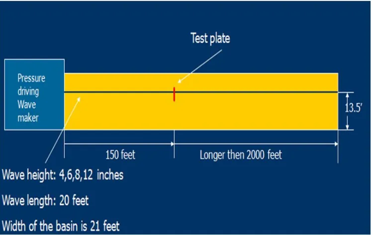
the measured results, particularly for extreme events in waves. An example of such variability is the testing in the long basin illustrated in Figure 1, in which a 20-foot long wave impinges on a flat plate. Figure 2 shows the variation in impact pressure that was measured during each different experimental condition.
[image:8.612.120.495.139.376.2]Figure 1: Test setup for flat plate wave impact simulations
Figure 2: Variability of the impact load in flat plate wave impact simulation.
Computational fluid dynamics can offer insight into physical phenomena. However, one should not assume that the most complex methods will always produce the best results. All methods have given both good and poor results, and require an understanding of the underlying physics to use them properly. Linear simulations will not correctly predict highly nonlinear problems and poorly resolved Reynolds-averaged Navier-Stokes grids will provide poorly resolved solutions.
The range of methods available is illustrated in Figure 3 (and also discussed further in the taxonomy section), going from the linear frequency-domain codes to Reynolds-averaged Navier-Stokes
tions. The linear methods are often good for conventional hull forms operating at various speeds. Potential flow methods can be used for nonlinear time-domain simulations with events such as slamming and whipping modeled separately. They require many hours of simulation in irregular waves. High-fidelity Reynolds-averaged Navier-Stokes methods are the dominant ship analysis tools used when viscous effects are important. Their use will continue to increase in the future. Large eddy simulation (LES) and hybrid RANS/LES methods are needed in examining complex flow structures where detailed turbulence information is needed for predicting ship performance.
Figure 3: Hydrodynamic methods. Taken from P. Temarel et al., Report of Committee I.2 Loads,
17th International Ships and Offshore Structures Congress, 16-21 August 2009, Seoul, South Korea, Volume I, Pages 127—210
Analysis of fluid-structure interaction is encompassed by a wide range of simulation tools and experimental information, but the most complicated tool is not needed for everything. There is a need to determine where two-way coupling is necessary for solving the problem or where separate analyses of the fluid and the structure are adequate. The more extreme events are typically the most problematic, especially as extreme events can happen in a relatively short time as part of a long duration event. Extreme events impact lifetime loads and need correct interaction, such as imposing slamming and whipping loads on top of normal hull girder bending. Validation of fluid-structure interaction analysis methods is complicated, and there is a need to ensure that the correct comparisons are made to make relevant conclusions. Issues of scaling of model tests need to be addressed. The ultimate question to be answered is whether there is trust in the analysis, computations, and experiments.
2.2 State-of-the-Art in Structural Simulations
Dr. Neil Pegg of Defence Research and Development Canada presented an overview of the current state-of-the-art in structural simulations. There are many different types of ship structure analyses depending on loading conditions and particular phenomena being investigated. Dr. Pegg presented three different taxonomies, dealing with analysis, structural response, and of fluid—structure in-terface (not interaction).
Fluid Structure Interaction: A Community View
• Static wave balance: In most traditional ship structural analyses, the ship is statically balanced on a wave, from which hull girder bending moments and other load effects can be obtained. These loads are used in simple beam theory calculations or in refined finite element analyses. In the static case it is assumed that there is no fluid-structure interaction between the ship structure and the hydrostatic loads.
• Quasi-static loading: In dynamic (quasi-static) loading by long waves, fluid-structure in-teraction is normally handled by a frequency-domain panel method hydrodynamic analysis code linked to a finite element analysis, with inertia forces required to achieve a balance of forces. This type of analysis is used with a design operational profile and statistics to obtain the extreme and cumulative fatigue loads for design.
• Vibration: Vibration calculations treat fluid-structure interaction through the concept of added mass effects, either by analytical calculations (Lewis forms and beam theory) or fluid elements in finite element calculations. In most cases the added mass is approximated as a constant. Vibration analysis of ship structure is performed on global hull and local structure, usually to avoid resonance with known forcing functions such as propeller excitation.
• Wave impact: Dynamic wave impact calculations are a more challenging aspect of fluid-structure interactions. Computational fluid dynamics methods are used as well as the results of model and full-scale experiments. Time-domain calculations are made, with possible sep-aration effects by cavitation considered. These analyses are used to augment quasi-static analysis to include whipping and springing and to get local pressure loads.
• Dynamic underwater explosion: Far field dynamic underwater explosions (UNDEX) are analyzed in fluid-structure interaction computations by boundary/acoustic elements. Exam-ple codes include the USA code. For near-field explosions, computational fluid dynamic codes such as the Chinook code are used. These methods can model the initial shock wave, bubble pulse, jetting, and bulk cavitation effects.
Each analysis approach has developed its own toolchain, acceptance criteria, and modeling ap-proach.
Different structural responses used today include:
• Elastic (stress-based) response measures
• Ultimate strength response measures
• Buckling prediction
• Fatigue life prediction
Additionally, there are many non-linearities that impact structural response, including load calcu-lations, material, and geometric non-linearities. In terms of fluid-structure interface, much of the work today is done with linear approaches. These approaches translate wave pressures over the entire hull into local stress ranges. The structure of many fluid-structure interface approaches in-clude a unit pressure taken per finite element on the hull, a unit wave per single heading, speed, or frequency of encounter in a hydrodynamics code, and the interface between hydrodynamic analysis panels and finite elements. In this interface the finite elements and panels do not usually match, and an interpolation to the finite element centroids is made and or the hydrodynamic panel pres-sures are calculated implicitly at the finite element centroids. These calculations are made with an
operational profile that defines the statistical wave spectra, headings, and speeds that the ship will encounter through its life or operation. This profile is used with hydrodynamic codes and finite element models to define extreme values and cumulative loads.
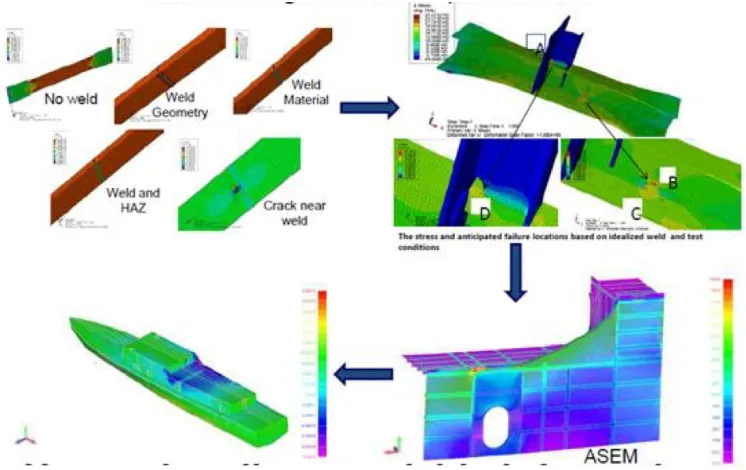
[image:11.612.121.494.206.441.2]A central challenge in structural analysis is that many failures originate at length scales that are orders of magnitude below platform size, as illustrated in Figure 4. Overall hull girder response to loading must be scaled down to local areas of irregular geometry, and these, in turn, must be scaled down to smaller-scale irregularities and possible defects (at the weld level) in structure to predict failure.
Figure 4: Range of scales and scalability challenge of structural calculations
The DRDC Below-Water Vulnerability Program works on the development of validated numerical models for naval platform vulnerability assessment. In model development, model validation is performed with experiments or sea trials to update the analysis models. Areas considered include high strain-rate materials, plates and stiffened panels, scaled hull girder whipping tests, and full-scale shock tests. Applications and deliverables include high-fidelity coupled computational fluid dynamics and finite element analysis for platform performance assessments, damage templates for design, and safe stand-off distances. Outcomes of these analyses are an improved understanding of the vulnerability of existing ships, improved force protection, and the improved survivability of future ships.
Another tool available is the Chinook/LS-Dyna coupling. Chinook and LS-Dyna are run in par-allel, with Chinook run on multiple processors for computational fluid dynamics, and LS-Dyna typically run on one processor for nonlinear structural response. Data is exchanged between the two codes at predefined coupling times, and the data exchanged depends on the type of coupling. For small-deflection coupling, the 2-way coupling exchanges data on pressure and velocity, but large deflection coupling also exchanges data on displacement of fluid and structure.
Fluid Structure Interaction: A Community View
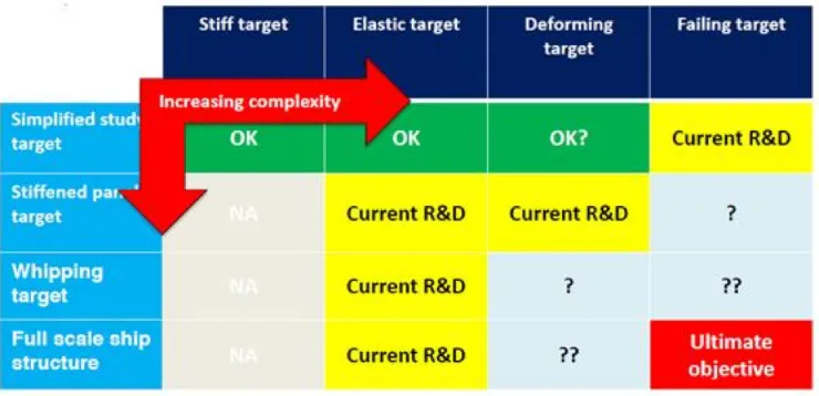
[image:12.612.121.491.191.370.2]international research programs. Close proximity underwater explosion effects have been jointly investigated by Canada, the Netherlands, and Sweden through a memorandum of understanding since 2005. The goal is to create a validated numerical prediction capability for the close proximity underwater explosion loading and damage. The scope of the program includes reduced-scale ex-periments to measure loading and response. Simulations of exex-periments are made with simplified loading models and improved material failure models based on measured high-strain rate proper-ties. The scope of the program is illustrated in Figure 5.
Figure 5: Scope of cooperative program in close-proximity underwater explosions
Slamming loads are being investigated in the program Cooperative Research Ships, which is pro-prietary to the 27 members, who represent shipyards, suppliers, operators, navies, classification societies, and research organizations. The program has undertaken a series of projects encom-passing experiments and numerical studies to try and predict structural loads from slamming by augmenting a nonlinear time-domain panel code with computational fluid dynamics (CFD) analysis of slamming to try and get complete pressure load time histories.
PANSHIP NL with Cooperative Research Navies has membership of the Canadian Navy, Nether-lands Ministry of Defence, DGA Hydrodynamics, Royal Australian Navy, Royal NetherNether-lands Navy, Royal UK Navy, U.S. Coast Guard, and MARIN. MARIN has led the effort to combine model tests, full-scale trials, data, and numerical simulations to better predict the complete load pressure history.
Computational fluid dynamics is now used routinely by Defence Research and Development Canada to predict propeller loads. Both panel codes (PROCAL) and Rankine-averaged Navier-Stokes (RANS) codes (ANSYS CFX, Star CCM+, OpenFOAM) are used. In general, the panel codes work well near design conditions, but the RANS codes are better at off-design or extreme condi-tions such as crashback, but are more computationally expensive.
A key part of validating structural predictions are full-scale trials. Tests and trials used to obtain data and verify and validate analysis methods range from small-scale component tests for fatigue, medium scale model tests for ultimate strength of structural members, large scale model tests for ultimate strength of the hull, and full-scale sea trials. One structural loads trial was conducted in 1997 on the destroyer HMCS Nipigon. The event had seven days of dedicated short term trials from
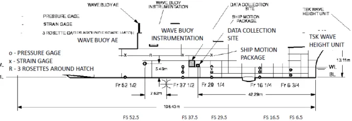
December 1 to December 11, 1997. Operations were conducted in the North Atlantic, Newfoundland Region in a range of sea states from a significant wave height of 1.5m to 5.5 m. Measurements were taken at 8 and 18 knots in five directions relative to the waves; head, bow, beam, quartering, and following seas. There were seventy runs, each run for 20 or 30 minutes in duration. Figure 6 shows the extent of instrumentation of the ship during the trials. The results of the sea trial measurements were then compared to finite element analyses as shown in Figure 7. Comparisons can never be precise because of the many uncertainties involved, including uncertainties in sea loads, as-built fabrication, material performance, limit states, and overall model uncertainty.
Figure 6: Instrumentation of HMCS Nipigon during 1997 sea trials
Figure 7: Comparison of measured strains from trials to finite element analysis of HMCS Nipigon
2.3 State-of-the-Art in Coupling Between Fluids and Structures
[image:13.612.122.490.378.607.2]Fluid Structure Interaction: A Community View
emerging coupling methods such as convergence properties, error bounds, computational scale and complexity, visualization and data transfer of huge datasets, and software engineering across legacy codes and pairing these codes to new high-performance computing architectures. One of the fluid-structure interaction coupling strategies that bear on naval applications is predicting hydrodynamic loading, including primary hull girder bending and predicting secondary loading such as slamming, whipping, and sloshing. Other applications include calculation of stability and seakeeping, maneu-vering and resistance, weapons effects, and multi-phase events such as spray and icing.
There are two general approaches to fluid-structure interaction coupling, loose and tight coupling. Loose coupling, also referred to as weak, staggered, or explicit coupling, is used for such problems as aero-elasticity and bridge engineering where the density of the fluid is much less than the density of the structure. An example of fluid-structure interaction in bridge engineering is the analysis of vortex shedding, which can cause large displacements when resonance of the vortices with the structure occur. Loose coupling usually adopts a partitioned coupling approach. Tight coupling, also referred to as strong or implicit coupling, is used for problems such as blood flow within vessels, heart valve motion, and ship hydrodynamic loading. Tight coupling may involve either monolithic or partitioned coupling strategies.
In loose coupling, within a given solution time step (increment), the pressures, and velocities in the fluid during the first half step are taken as those of the structure in the subsequent half step; thus completing the time step (increment). In tight coupling the pressures and velocities of the fluid and the structure are iterated on, to ensure satisfaction of conservation equations, before closing out the time step. Also within the context of tight coupling, the contribution of mesh motions to the conservation equations must be considered (e.g. using arbitrary Lagrangian-Eulerian (ALE) methods). In some conditions, loose coupling will remain stable through successive iterations, but in other cases numerical instability may occur, and tight coupling will be required.
In naval applications tight coupling will sometimes be required because of the density ratios and problem domain geometries. Two types of tight coupling are used, monolithic and partitioned coupling. With monolithic coupling the tight coupling begins at the level of governing equations of the fluid-structure interaction system. There is a single data structure that embodies discretization of the fully coupled linear system of fluid and structure. A single solver is used for the combined fluid-structure system. With partitioned coupling two different solvers are used, one for the fluid, and one for the structure. Partitioned coupling requires software coupling to glue the two indepen-dent solvers together in a principled way. The coupling physics is handled by the software coupling, which must respect the particulars of the individual codes to be coupled.
Monolithic coupling offers the advantage that the coupling occurs at the governing system level, the tightest scheme available. With a self-contained fluid-structure interaction solver there is less communication overhead during the interaction solution and there is a single software tool that will need to be maintained. However, monolithic coupling is not ideal because a single solution strategy (e.g. the finite element method) must be used for both the fluid and the structure. The coupled system contains very different types of field variables, and so numerical ill-conditioning is a concern. Because of the constraints on keeping the solution strategy for the fluid and structure the same, it is difficult to update the solver to match advances in the state-of-the-art for each component, such as the latest turbulence or materials models.
Partitioned coupling is advantageous in that having separate solvers allows for the most efficient
solution approach for each domain in the problem: using finite elements for the solid and finite volumes for the computational fluid dynamics. Partitioned coupling leverages the existing sub-stantial investment in legacy code development and permits the legacy codes to continue to evolve independently of each other. However, partitioned coupling requires a robust coupler that properly respects the conservation of mass, momentum, and energy within the FSI transmission conditions. Partitioned coupling requires careful consideration of communication overhead to remain efficient and it is difficult (or potentially impossible) to prove things formally about convergence and solution error bounds since the fluid and structure domains are modeled using different methods (i.e. finite volume and finite elements in the same analysis).
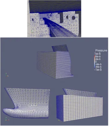
An example of the use of monolithic coupling is shown in Figure 8, where a numerical analysis was made of the model of the notional Joint High-Speed Sealift ship. The model had an internal spline along its length to support the sections of the model and to determine bending moments as the model was tested in waves. The figure shows the finite elements used for the structure and for the fluid.
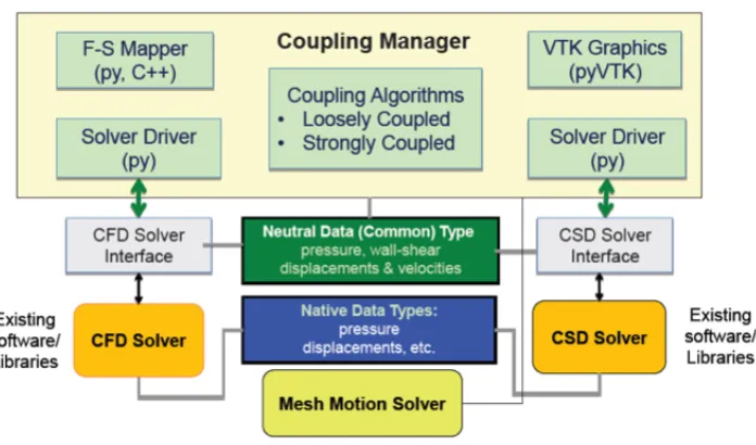
A schematic of the partitioned coupling scheme is shown in Figure 9 where the coupling manager software uses several interfaces to simultaneously run the computational fluid dynamics code and the computational structural dynamics code. Partitioned tight coupling can be computationally expensive as conservation of momentum, energy, and mass must be respected at the structure-fluid interface at the end of each solution time increment. This requires sub-iterations during each time increment to achieve the desired conservation to user-specified tolerances. Additional complexity in the conservation laws arises from the need to update the fluid mesh boundary during sub-iterations in accordance with the arbitrary Lagrangian-Eulerian (ALE) finite element formulation in which the computational system is not a priori fixed in space.
An example of using partitioned coupling is shown in the solution of Turek and Hrons Problem, Case FSI3 in which a flexible plate is held in a moving fluid as shown in Figure 10. The finite-element code CU-BEN has been coupled with the computational fluid dynamics code OpenFOAM.
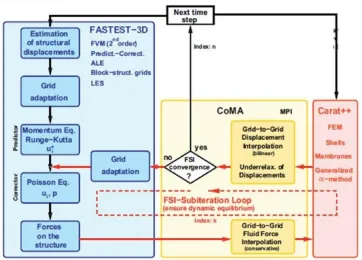
Alternatives to the tightly-coupled partition approaches, which are expensive to run, are the semi-implicit schemes, developed for problems where strong-enough coupling is sufficient. A diagram of the process is shown in Figure 11. With semi-implicit coupling, mass and momentum are conserved, but energy is usually not quite conserved, which is likely not a big concern for subsonic flows in naval applications. Known stability proofs for semi-implicit schemes are based on an analysis of the resulting weak form description of the governing coupled system, thus restricting application to cases where finite elements are used for both the fluid and the structural domains.
Fluid Structure Interaction: A Community View
Figure 8: Monolithic coupling applied to the analysis of the notional joint high-speed sealift ship. The upper figure shows the detailing of the internal structure of the splined ship model that had been tested in a wave-making tank.
3
Summary of Use Cases and Future Needs
3.1 Use CasesWorking with engineers from NSWCCD, several current and anticipated FSI use cases were de-veloped in slide format. These slides were circulated to the working group attendees for reflection before the working group. During the fist day of the working group, the participants were divided into nine groups of five people. Three groups addressed platform (global) level FSI responses. Four
Figure 9: Partitioned coupling between the computational fluid dynamics (CFD) solver and the computational structural dynamics (CSD) solvers. (Kim and Miller, NSWCCD)
Figure 10: The analysis of flexible plate in a moving fluid analyzed in a partitioned coupling scheme.
groups addressed local level FSI responses. Two groups addressed propulsor and appendage FSI. Each group was tasked with reviewing the proposed use cases, and then adding corrections and proposing new use cases. In a wrap-up session, the groups in a common area met and combined their outputs from the day. These slides were then printed on large-format paper and placed for final open comment via sticky notes at the working session on the final day.
[image:17.612.119.491.340.570.2]Fluid Structure Interaction: A Community View
Figure 11: Semi-implicit coupling (after Michael Breuer et al. Fluid-structure interaction using a partitioned semi-implicit predictor-corrector coupling scheme for the application of large-eddy simulation. Journal of Fluids and Structures, 2012, 29, pp.107-130.).
First, for each use case the groups were asked to plot current numerical or experimental methods on axes of fidelity — one for fidelity in the fluid domain and one for the structural domain. Such points represent concepts or techniques, not specific simulation codes or experimental facilities. Each point on the graph was also assigned a Technical Readiness Level-inspired readiness level. These engineering methodology readiness levels (EMRL) follow the following definitions:
• EMRL 0 Future academic proposals
• EMRL 2 Current academic research at PhD level
• EMRL 4Code or protocol formulated, but only usable by developer, no or limited verification and validation
• EMRL 6Code or protocol documented, usable by small number of experts, some verification and validation
• EMRL 8 Code or protocol in widespread use, verification and validation largely complete
The method fidelity plots help compare methods in term of their current readiness and potential for future development. Finally, each group also came up with a future vision plot. The vision plot proposes a wish-list of potential research topics for five, ten, and twenty years out. Additionally, future applications of FSI methodologies were also listed. These applications included both spe-cific platforms, as well as more general techniques that would impact multiple platform types or acquisition programs. For the global and local FSI areas, one EMRL plot was made per use case, with one future vision plot for the entire area. For the propulsors and appendage FSI, the working
teams felt an alternative approach would better describe their domain. A common ERML plot was made for all applications, but separate future vision plots were made for each use case. The full plots and text generated are included in the appendix of this report, the remainder of this section briefly summarizes them.
For global loading, the dominant use cases were integrated global loads on monohulls and multihulls, underwater explosions, and flexible (fabric) structures. For integrated global loads, several mature simulation capabilities exist, however, determining extreme event sequences and load combination methods are not as mature. Additionally, preliminary design tools for multihulls are currently lack-ing. Underwater explosions and flexible structure techniques are evolving but overall were rated less mature. Here, integration of local responses or failure modes into the overall global loading is still needed. The groups involved in this area of discussion saw many future research challenges, improved hydro-elasticity, methods of different fidelities, improve FEA model generation were all cited as near-term goals. Longer-term goals include tying models to local deformations and fail-ures, increasing computational capacity, and understanding difficult phenomenon such as structural damping. Short term applications involve predicting a single extreme event for physics-based rules, while longer-term applications include multiple extreme events, better understanding of when FSI is needed, and finally comprehensive lifetime simulation.
For local FSI, significantly more use cases were considered. These include impact and slamming on boats, local slamming pressures, sloshing, cumulative damage from local external slamming, AIREX, wave slap and secondary non-impact pressure, and ice impact. The last three use cases were not discussed by the groups at the Ann Arbor event, so the input on these cases comes only from prior input from small group discussions. In general, techniques for local FSI were seen as less mature than global FSI, with most ERML values at 4 or less, and many areas having EMRL values between 0 and 2. In this area, it is clear that current work in FSI is focusing on two-way coupled codes capable of handling viscous fluids, with the desire to extend to non-linear structural response. Much work is being done on the transition to multiphase fluid flows as well. Under-standing the boundary conditions — e.g. the motions and maneuvering of small craft that set up the impacts — is also a central challenge. This is also true for large-ship local FSI, where accurate boundary conditions from both the global ship motion and distributed wave field are required. For future goals, broad developments in experimental, numerical simulation, and data processing were all identified. Longer term goals include improved sensing, and transition to design tools. Veri-fication and validation, as well as uncertainty quantiVeri-fication were also highlighted by the groups. Future applications consist of both scale experiments to support research goals, as well as improved lifetime prediction capability for platforms.
Fluid Structure Interaction: A Community View
disciplines.
For numerical methods, multi-phase turbulence modeling, improved composite material modeling, and better coupling, especially to acoustic codes were short term goals. Longer-term goals extended on these short-term goals to include integration with control, real-time structural health detection, and ability to handle maneuvering platforms. Reduced-order models for design were also identified as a research need. New experimental methods identified include the need to be able to simulta-neously measure hydrodynamic, structural, and acoustic phenomenon. Progression of applications saw the short-term application of small deflection, passively-controlled appendages, with a move towards larger deflections, active control, and smart materials in the 10—20 year time frame.
3.2 Future Needs
At the end of the first day of the Ann Arbor event, participants identified common or interesting research challenges from their day one discussions on post-it notes. The event organizers met that night, reviewed the notes and use cases presented, and developed eight questions on future research to be answered on day two. These questions were answered in group settings, in two rounds of four questions so each participant could provide their input on two questions. Each group then presented their discussion to a plenary session, where further questions and suggestions were made. Finally, a walking poster session was held where participants could further comment on any topic of interest. The questions and a brief summary of the responses are listed below. In many cases, the responses to the questions were quite varied, so the summaries below only capture major or com-mon points. In the appendixes to this report, the full questions, sub-topics, and complete responses (including plenary discussion and walking poster session issues) are presented. This more detailed description should be consulted to get an idea of the full scope of the discussion around these is-sues. A future working group dedicated to a further exploration of these topics would be worthwhile.
1. How can we better utilize machine learning and data processing to improve the generation and understanding of large experimental and computational data sets? Improvement in both automating gridding and geometry, as well as pattern recognition and dimensionality reduction of output sets, were identified. How to exploit legacy data, and how to use machine learning to replace physical models were also mentioned.
2. What are the current limitations of fluid simulation methods for FSI problems and how can we reduce them? Improvements from design models, potential flow models through LES models were all requested. The ability to model acoustics and erosion on appendages were highlighted. UNDEX modeling, multi-phase cavitation, including multiple time scales of the different processes involved were also mentioned. The ability to blend multiple fidelity simulations in one model either spatially or temporally, and the ability to correctly identify phase-resolve waves leading to extreme events to simulate was also identified. 3. What are the current limitations of structural mechanics solution methods for FSI problems and how can we reduce them? Challenges around scalability of calcula-tions, the ability to automatically mesh/re-mesh after damage or fragmentation were noted. The ability to refine meshes automatically around local damage or failures was particularly highlighted. Composite/metal joints and structural damping also need further investigation. Modeling approaches short of 3D-FEA for early stage design was also highlighted.
4. What are the current limitations of coupling approaches to FSI problems and how do we address them? Convergence of the coupling approaches used today, guid-ance on best practices, along with experimental validation, were all seen as near-term goals. Longer term goals include working on more complex problems — fragmentation, bubbly flows, and uncertainty quantification. A standard coupling application programming interface or specification was also highlighted.
5. What physics and applications require us to address the full 2-way coupled FSI problem? When can we use other approaches? This question was seen as largely unan-swered at the current time, with approaches including parametric exploration and machine learning proposed to develop this knowledge for increasingly complex problems. A long list of factors to consider for this decision was generated and discussed during the floor session. Uncertainty quantification and coupling to non-linear codes were also highlighted.
6. What are the current needs for Verification and Validation? What uncertainty quantification developments are needed? A set of clear, canonical problems with iso-lated physics was seen as a near-term goal. Careful structuring to understand coupling, scaling, and facility bias will be needed. Collaboration between experimental design and nu-merical simulation was also needed. Longer term goals include better uncertainty estimation and sensing capabilities.
7. What experiments are required to advance our understanding of FSI? A series of increasingly complex benchmarks were proposed. These start with simple single-phase, forced motion cases and run through larger multiphase problems. The spatial scale of the model should start with simple components and proceed through more ship-like models. Clarity in boundary conditions, repeatability, understanding of scale effects, and the ability to make the data accessible to the community were all highlighted. Developments in instrumentation would also be required.
8. What are the key problems with user training and human interaction with com-plex FSI numerical simulations? Ideas including blind tests, consortia of developers, and promoting shared code ideals were all discussed.
4
Taxonomy and Scope of Application
Over the course of several FSI events, it became clear that there wasn’t a clear definition of:
• What exactly constitutes FSI
• How development in different FSI “stovepipes” connected or could support each other
• The complete scope of activities required to go from defining an FSI problem to actionable information for platform design or analysis.
Fluid Structure Interaction: A Community View
— other perspectives are equally valid and could be more useful in certain applications. However, as a way of enabling cross-discipline communication and showing the relationships between various FSI efforts, the current imperfect model is presented in this section.
4.1 Taxonomy
4.1.1 Description of FSI Problems
[image:22.612.75.530.294.669.2]At the end of the first day of the Ann Arbor event what constituted FSI was unclear. Several participants noted that some of the use cases presented did not fit their working definition of FSI. However, follow-up questions revealed that there wasn’t a standard FSI definition shared by the community. Based on these discussions, and a review of the use case comments, the following simple taxonomy is proposed to classify FSI problems. It is important to note that this taxonomy focuses only on theproblem not thesolution strategy to the problem. Solution approaches, in both the fluids and structures domain, are discussed in the next section.
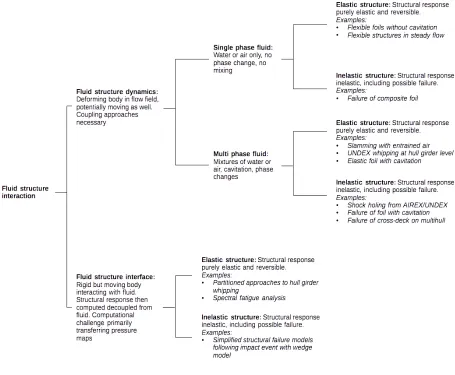
Figure 12: Draft taxonomy of FSI problems by fluid and structural model approach
During the workshop, two main branches of FSI emerged. The first, the lower branch of Figure 12,
was termed fluid-structure interface. The lower branch normally involves a rigid body moving through the fluid, and pressures from that body being recorded and transferred to structural mod-els. This approach is marked by a lack of feedback from the structural deformation to the fluid domain — a partitioned approach. While it was clear that many use cases relied on fluid-structure interface, many participants did not consider interface part of the traditional fluid-structure interac-tion (FSI) domain. However, the rigid body is still interacting with the fluid, changing the fluid from radiation and diffraction interactions, so it was decided to include this under the large umbrella of FSI, but as a separate branch. Many codes and approaches in this area appeared mature and tested.
The other primary branch was named Fluid-structure dynamics (FSD). Here, the deformations of the body are transmitted back into the fluid solution, though the degree of coupling may vary from simple one-way time-stepping coupling through to more complex iterative two-way schemes. FSD was further divided by the type of fluid model used, either single or multi-phase flow. Single-phase flow indicates the presence of either air or water in the fluid simulation, where multi-phase indicates a changing mixture of fluid and air through effects such as cavitation or bubbly flows. Further-more, the type of structural model used, either elastic or inelastic can further classify the problem. The most complex FSI problems are the multi-phase inelastic approaches, for assessing ultimate strength under weapon or fluid impact loadings.
What emerges is a simple taxonomy that is useful in classifying FSI problems or prediction capabil-ities by asking no more than three questions. First, does the structural deformation influence the fluid? Second, does the fluid consist of one phase? And third, is the structural model fully elastic? Some thought was given to the timescale of the FSI problems as well, but it was decided not to add time to this hierarchy as many of the slower-responding problems naturally group themselves in the fluid-structure interface branch. Differences of time scale beyond this are usually more relevant in developing solution approaches, not describing problems.
4.1.2 Description of Numerical FSI Solution Methods
Fluid Structure In teraction: A Comm unit y View
Table 1: Table of computational fluids dynamics (CFD) approaches
CFD Type Assumptions Uses and Description Codes Computational
Requirements
Typical Run-Times
Potential Flow Solvers
Conformal Trans-forms • Inviscid • Irrotational • Incompressible 2D
Two-dimensional lifting surfaces. The shape is defined by performing a series of coordinate transformations of flow past hydrodynamic [mathematical] sin-gularities (sink, source, doublet, or vor-tex) in the complex plane.
• Customized codes Workstation Seconds Integral Methods (Panel, Boundary Element, Poten-tial) • Inviscid • Irrotational • Incompressible
External flows around complex geome-tries where the boundary layer is thin. The boundary is defined by small pan-els containing hydrodynamic [math-ematical] singularities (sink, source, doublet, or vortex). It is generally good at calculating lift and pressure drag when flow remains attached. Used for aircraft and ship lift and drag calcula-tions.
• Das Boot
• FREDYN • Tempest • LAMP Multi-core or multi-processor workstation
Minutes to a few hours
Inviscid Flow Solvers
Euler • Inviscid All flows where negligible viscosity is a good assumption. Solved on a dis-cretized domain. The equations are el-liptic when flow is steady and hyper-bolic when it is not.
• SAIC NFA
• Customized codes
• All RANS and LES codes Multi-core or multi-processor work stations Hours Viscous Solvers
Navier-Stokes • Laminar
• Continuum
All flows where the maximum Reynolds number indicates the flow is below the transition to turbulence. Solved on a discretized domain.
• SAIC NFA
• Customized codes
• All RANS and LES
Multi-core or multi-processor Workstation or cluster
Hours to days
2016-003
Fluid Structure In teraction: A Comm unit y View
CFD Type Assumptions Uses and Description Codes Computational
Requirements
Typical Run-Times
Direct Numerical Simulation
• Continuum Solves the complete Navier-Stokes equations on a discretized domain. Generally limited to very small do-mains because it requires an extremely fine grid (Kolmogorov scale) and ex-tremely small time step (to meet Courant condition).
• Customized codes
• Many RANS and LES codes
High-performance computer
Days to week
Reynolds-Averaged Navier-Stokes (RANS) • Turbulent • Continuum • Turbulence modeled
• Steady flow
Solves the RANS equations on a dis-cretized domain for flows where the majority of the domain is above the transition to turbulence.
• UNCLE
• Navy FOAM
• Fluent • CFDSHIP-Iowa • STAR-CCM High-performance computer
Hours to days
Unsteady Reynolds-Averaged Navier-Stokes (URANS) • Turbulent • Continuum • Turbulence modeled
Solves the unsteady RANS equations on a discretized domain for flows where the majority of the domain is above the transition to turbulence. It implicitly assumes that the empirical turbulence models developed from steady flow con-ditions remain applicable.
• UNCLE
• Navy FOAM
• Fluent • CFDSHIP-Iowa • STAR-CCM • Comet High-performance computer
Hours to days
2016-003
[image:25.612.52.743.99.418.2]Fluid
Structure
In
teraction:
A
Comm
unit
y
[image:26.612.59.754.95.566.2]View
Table 1: Table of computational fluids dynamics (CFD) approaches
CFD Type Assumptions Uses and Description Codes Computational
Requirements
Typical Run-Times
Large Eddy Simu-lation (LES)
• Turbulent
• Continuum
• Turbulence modeled to subgrid scale
Solves the low-pass filtered Navier-Stokes equations on a discretized do-main for flows where the majority of the domain is above the transition to turbulence. It implicitly assumes that the empirical turbulence models devel-oped from steady flow conditions re-main applicable and that the small scale turbulence has a universal struc-ture.
• Navy FOAM
• Fluent
• SAIC NFA STAR-CCM
• Comet
High-performance computer
Hours to days
2016-003
Fluid Structure In teraction: A Comm unit y View
CSM Type Assumptions Uses and Description Codes Computational
Requirements
Typical Run-Times
Simplified Engineering Methods
Rigid body dy-namics
• Rigid body mo-tion
• No structural response
Used to capture overall body motions e.g. ship hull in waves. Can be used to extract local pressures where FSI ef-fects are minimal.
• LAMP
• OpenFoam
• Customized codes
Virtual none but depends on fluid code
Seconds to days
Panel level and structural unit level models
Reduced order models of local response in valid range
Used to determine structural response characteristics on local level to inform global level e.g. panel response to capture hull girder behavior or global stresses for fatigue analysis.
• ULTSTR • Hullwhip • MAESTRO • Customized codes Multi-core work-station
Seconds to min-utes
Finite Element Analysis (FEA) Methods
Linear FEA • Response is linear i.e. no yielding, contact, severe deformations
Used to determine global and local level material and structural response in a single analysis for a wide variety of loads ranging from wave loading to underwater explosions. High utility in determining inputs for secondary anal-ysis for determining fatigue, equipment response, and allowable stress levels for safe operation. • NASTRAN • ABAQUS • SIERRA/SD • MAESTRO • Others Multi-core work-station to High-performance com-puter
Seconds to days
Non-Linear FEA • Non-linear ma-terial or struc-tural response
Used to determine global and local level material and structural response in a single analysis for severe loads e.g. weapons effects, collision, grounding, ultimate hull-girder strength. Success-ful execution requires extensive defini-tion of inputs and high level of analyst experience. • ABAQUS • LS-DYNA • SIERRA/SM • DYS- MAS(PARA-DYN) Multi-core work-station to High-performance com-puter
Hours to days
2016-003
[image:27.612.57.746.96.527.2]Fluid Structure Interaction: A Community View
4.2 Scope of Application
Much of the previous exploration of the FSI problem domain focused primarily on the problem of simulating the physics of FSI events. However, it was clear in talking to end users in indus-trial settings such as the American Bureau of Shipping (ABS) and governmental settings such as Naval Sea Systems Command (NAVSEA), United States Coast Guard (USCG) and DRDC that the challenge in FSI predictions extends beyond simulation of physics. In Figure 13, a wider view of implementing FSI prediction methods is shown. The goal of this figure is to document what sorts of supporting activities are occurring in parallel with the development of new methods of predicting the physics of FSI problems. These supporting activities often frame the problem, provide data to validate FSI simulations or turn FSI simulations into decisions. Understanding the scope of the problem is necessary to fully understand the scope of work underway for FSI solutions.
The rough flow of Figure 13 is top to bottom, showing the components required to make a decision on a FSI problem. These activities do not need to follow this flow temporally — for example basic research developments in simulation technology start independent of a specific need and then are picked up by engineers when the need arises. However, the items shown on the chart are viewed as necessary for a complete engineering prediction. Proceeding with gaps in the chart increases the possibility that the engineering prediction will lead to an incorrect decision. In reality, the links shown in the chart may be bi-directional or iterative. The correct physics may not be initially identified, and after trying one type of model, it may be necessary to go back and re-evaluate what is important. Additionally, for local phenomenon, FSI predictions may also rely on linked global models to get correct boundary conditions for both the platform motion and flow field. However, for clarity on this plot, the iterative nature of development is not explicitly shown.
Starting at the top of the chart in the blue color, a need for a type of FSI prediction is posed, and the dominant physics involved is identified. This leads to three related pathways — investigating the phenomenon through full-scale measurements, model scale experiments, and numerical simulation. Should numerical development be selected, there are a number of areas in which this development may take place. This is shown in the green-colored nodes on the top-left of the image. During the FSI working group discussions, it was clear that there are many current avenues for numerical improvement underway. In addition to adding new physics to numerical simulations, code acceler-ation and data analysis topics now feature prominently in this area of development. Additionally, such codes should be verified, or shown that they faithfully implement the desired numerical model.
Both full-scale trials and model-scale experiments are also avenues for investigation of FSI problems. Here, much of the discussion in the working group centered around the need for developments in both instrumentation and facilities. Many FSI events are highly dynamic, short time-scale events and the ability to accurately sense and record both the fluid and structural response in 3-D space during such events remains challenging. During the working group meeting, it was clear that there was a strong desire for canonical FSI experiments on simplified geometry to help in code validation and understanding of critical physics. Additionally, full-scale trials often need the ability to both understand and sense the operational environment of the vessel. Data from full-scale trials and more complex experiments can be used to directly address the FSI question, or can be used to further validate either model-sale methods or numerical methods.
Such validation campaigns are extensive, and with modern sensors, the amount of data created is large. Thus, archiving, visualizing and using this data, both for direct FSI prediction and numerical
simulation validation was seen as a key step in the process. These processes are shown in the red, yellow, and orange boxes in the center of the chart. Note that here too there is a “big data” problem that needs to be confronted, as modern data acquisition systems can quickly generate terabytes of data. Thus, data mining, visualization and archiving also appear in this part of the chart.
The combination of numerical, experimental, and full-scale trials can be used to understand better the physics of FSI problems. However, to make a design or operation decision from such simula-tions requires further information. Acceptance criteria — related to the likelihood of the response occurring and the consequence of the response must be established. Developing such criteria re-quires understanding of both the variability in the FSI process and the extreme responses that may be seen in service. Some of the required processes for generating such information are shown in the light blue box on the lower right hand side of the chart. To make a decision based on FSI simulation, several pieces of information are needed. First, some sort of uncertainty quantifi-cation is required to evaluate the uncertainties in inputs to the FSI simulation and their impact on the results. Additionally, prediction bias and variation must be estimated as well. Together, these measures will give a statistical idea of the magnitude of the variability of the FSI predic-tion, and how large a safety margin may be needed in service. Such stochastic description of the uncertainties also form the basis for reliability analysis of extreme events, also discussed in this box.
A second challenge is fully understanding the operational environment of the platform. Under-standing when the conditions likely to cause a significant FSI response will occur, and how frequent such conditions are forecast to be over the vessel’s life is also required. Such probabilistic charac-terization is needed to understanding the likelihood that particular levels of response will occur. As most FSI processes are inherently non-linear (with the notable exception of some fluid-structure interface problems discussed above), a final challenge in this box is understanding the extreme, or design values of the response. If sufficient simulations can be run, and the physics of the problem behaves well-enough (does not change at extreme responses), it is possible to fit statistical descrip-tions to these simuladescrip-tions and extrapolate extreme responses.
However, such extrapolation may not always be practical owing to either lack of data or complex FSI responses that are hard to describe with a small number of parameters. Additionally, such extrapolation procedures have the disadvantage that the actual extreme response is no longer being simulated with either numerical or experimental methods — it is an extrapolated response detached from any specific simulation. An alternative approach is to characterize stochastic processes so that inputs likely to produce extreme outputs can be identified. Such approaches allow snippets of the underlying process to be directly simulated with numerical or experimental tools, thus allowing the entire build up and extreme response to be computed, visualized, and studied. These approaches are still at a research stage but may offer an alternative approach to developing design responses that can be used for decision making.
Fluid
Structure
In
teraction:
A
Comm
unit
y
[image:30.612.55.734.72.550.2]View
Figure 13: Contributing components to an FSI Decision
2016-003
5
Discussion
An image of a large and dynamic community emerges from the analysis of the proceeding sections. As anticipated from previous FSI workshops and conferences, historically this community has been divided into specific domains. However, the Ann Arbor event showed that such divisions do not preclude fruitful exchanges of ideas and collaboration when the opportunity arises. In this section, certain themes that appeared significant or repeatedly appeared are presented, along with some discussion of their implications. As the objective of this effort was to document and report, not prioritize, no effort has been made to turn these into a prioritize list or strategy. Specifically, future naval strategy and budgetary limitations were not addressed at the event or in this report, both of which would be required before assessing priority. Exclusion of concepts from this discussion also does not imply a lack of priority — several concepts appear self-explanatory and will not be repeated here.
One of the most significant findings was that the community itself did not have a common work-ing definition of fluid-structure interaction. Many application-focused engineers would lump large wave-body interaction problems into FSI, while the more research-oriented members tended to define FSI more narrowly in terms of two-way coupled problems. It is hoped that the taxonomy proposed here, and the listing of the types of approaches will help the community understand which part of the FSI problem is being discussed.
It is equally clear that the community has a long list of research challenges. Numerical code im-provements, experimental facility and instrumentation development, as well as full-scale trials and validation continued to bubble up in different group discussions. Several topics appeared especially frequently. First, there is a clear desire for the continued development of FSI models of varying fidelity — reduced order models for design, potential flow, RANS, LES were all requested. Many of the EMRL plots created on the first day of the Ann Arbor event contained methods ranging from EMRL of eight to two. The range in EMRL levels further indicates that there is a wide variety of tools in use and development at the current time. Often, this means that there is a tool-to-problem matching problem, in that for each application engineers must select the appropriate modeling strategy. Coupled with this there is a need to train engineers in the capabilities, assumptions, and limitations of these methods. Accessibility and transferability of codes from academia to end users such as NAVSEA, ABS, USCG, DRDC are parts of this challenge.
Computational improvements at the higher end of our current capabilities were also highlighted repeatedly. In general, coupling approaches, FEA structural models with non-linear responses including failure/fragmentation, and the higher-end viscous flow simulations were all specifically identified as needing further development to meet projected use cases. Coupling approaches ap-peared generally less robust than baseline fluid and structural modeling approaches. The problem of modeling large spatial domains with different levels of fidelity in different regions was also seen as a common challenge. The structural community is primarily worried about capturing local fail-ures in connections, or being able to remesh and model progressive damage starting in one area of the structure. The fluids community is interested in differing resolutions close to interfaces with boundary layers or multi-phase boundaries, while the general fluid can be represented in a coarser fashion. The desire to capture such spatial variation is in part driving the desire for more compu-tational power.
meth-Fluid Structure Interaction: A Community View
ods at model scale, full-scale trials, and numeric computations are capable of rapidly generating terabytes of information. Data sets of this size pose a number of challenges. The mechanics of storing, transferring, and archiving them are difficult. For numeric computations, it is common now to process on the high-performance computer where the code was run. HPC-based post-processing works fine for the immediate needs of the project, but if the data set is to be shared, or if there is a desire to re-analyze the data at some point in the future, it is not clear that this model will work. Often, the researcher does not own or control the high-performance computer, and may not be able to assure access to the machine, the data, and the required software in the future. Experimental data sets are more likely to be under the direct ownership of the researcher, but the challenges of archiving and sharing such data remains.
Beyond the mechanics of transfer and access, such large data sets pose additional problems. The ability to visualize such data, ask questions, and identify critical results is not well developed for data sets of this size. Machine learning and data mining approaches may help in this regard. How-ever, among the experts assembled in Ann Arbor, there was little technical understanding of what would be required to allow this to take place. Here, tighter collaboration with computer scientist and information experts is probably warranted.
Cross-discipline collaboration also emerged as a strong theme. While not all FSI problems have compatible time-scales or physics, it was clear that there was common ground in several areas of code development (specifically coupling) as well as instrumentation and experimental analysis. Also notable was the strong desire between experimentalist and numerical analysts to collaborate on benchmark experiments. It was clear that the experimentalist felt they would benefit from designing the experiments in collaboration with numerical simulations. Developers of numerical codes also felt that it would be beneficial to be involved in the experimental design. The ability to adjust the experimental program and numerical models in parallel during the design, execution, and post-processing of the experiment would be of significant value. This points towards the need for integrated planning of future experiments across multiple organizations. Several current projects that might provide a proof-of-concept for this approach were mentioned at the event.
Finally, some areas were identified during the small-group study phase of this project and the post-processing of the Ann Arbor event that appear significant, but were not discussed in detail. First among these is the need to generate extreme or design cases to study with the higher-end FSI ca-pability. It is clear that at the high end, the analysis of a short event will still consume hundreds to thousands of CPU hours, implying that only a limited number of analysis cases can be considered. Especially for wave-induced responses, a challenge emerges in trying to efficiently determine what series of wave elevation inputs (phase-resolved wave train) would produce an extreme response. The ability to generate such sequences, along with a reasonable probability associated with them occurring (or no higher response occurring) would significantly improve the ability to apply such FSI predictions in approval settings.
Additionally, the impact of the human analyst was highlighted in the complete scope of the FSI application, but not discussed at the workshop. For many codes, the answer can change depending on the modeling options and procedure used by the analyst. Additionally, not all options and fea-tures are rigorously documented, further highlighting the experience of individual analysts. This situation becomes even more complex when the results of the analysis are written up and often passed on for further discussion and decision making. At this stage, there is a large loss of informa-tion about assumpinforma-tions, limitainforma-tions, modeling strategy and what is truly significant in the results.