2019 International Conference on Artificial Intelligence and Computing Science (ICAICS 2019) ISBN: 978-1-60595-615-2
Analysis and Design of an Effective Energy Utilizing TEG System
Xiao-ying YANG, Shi-peng LIU, Lin-wei CHEN, Jing ZHOU and You-ling YU
*School of Electronic and Information Engineering, Tongji University,Shanghai 201804,China *Corresponding author
Keywords: Thermoelectric generation, Temperature difference model simulation.
Abstract. Thermoelectric generation (TEG), the theoretical basis of which is the Seebeck effect, is a new energy-saving and environmentally-friendly power generation technology that directly converts thermal energy into electrical energy. The TEG system has the advantages of simple structure and maintenance-free, and can be used for the conversion of small and medium-sized waste heat in life and electric energy. The heat source is widely distributed, and the generated electric energy is accumulated in a small amount, thereby effectively promoting the construction of a green city. This paper introduces the composition of the TEG system, and verifies its feasibility by establishing models and analytical calculations.
Introduction
[image:1.612.76.538.383.535.2]Thermoelectric generation(TEG)can directly convert thermal energy into electrical energy, which is a new type of green power generation. Compared with traditional energy and new energy, the temperature difference energy(TDE) has many merits, as is shown in Table 1.
Table 1. Characteristics of different energies.
Energy resources Generation and usage mode
Environmental
protection Equipment safety Universality
Traditional energies: coal, oil, etc.
central electric power system
resource-constrained, severely polluting
large and complex equipment: turbine, boiler etc.
natural existence in limited areas
New energies: solar, wind energy, etc.
central electric power system green, renewable, non-pollution complex mechanical structure, time-consuming maintenance commonly existing, affected by weather
TDE distributed electric power system green, environment-friendly
no moving, mechanical components,
maintenance-free
ubiquitous
The superiority of TEG is manifested in the wide range of TDE sources. Besides, the TEG device is small in size, simple in structure, free from mechanical movement, maintenance-free and so on. It can simplify the structure of the TEG system, collect small waste heat everywhere in life, and accumulate energy, improving energy efficiency and improving energy structure. It is an indispensable component of a smart green city.
Principle of the TEG System
The Electricity Generating Principles
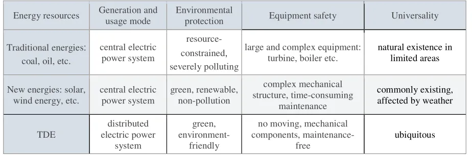
[image:2.612.91.522.73.192.2]
(a)PN couple unit (b)Structure of TEG module
Figure 1. Operating principle of TEG module.
As shown in Fig.1, several P and N type semiconductors are connected in series to form a TEG module, and the potential difference between the two nodes of the cold end is the sum of the potential differences of all the semiconductors, that is, the Seebeck voltage, calculated using Eq. 1. SB (T) and SA (T) are the relative Seebeck coefficient of the P-type and N-type semiconductor material respectively. If SB (T) and SA (T) do not change with temperature, Eq. 1 is reduced to Eq. 2.[1]
The Seebeck coefficient of common semiconductor materials is shown in Table 2.[2] The TEG module selected in this system is Bi2Te2, which is cost-effective and has high power generation efficiency.
Table 2. Seebeck coefficients of materials.
Materials SB[μV/K] Type Materials SB[μV/K] Type
Bi2Te3 260 P Bi2Te3 -270 N Sb2Te3 133 P Bi2Se3 -77 N P0Te 380 P P0Te -320 N Si0.8Ge0.2 540 P -
-B4C 250 P -
(1)
(2)
Composition of a TEG System
[image:2.612.157.449.566.713.2]Conversing thermal energy into electrical energy, then storing and using the energy, a TEG system can be divided into three parts: thermoelectric conversion, electric energy conversion, and electricity consumption. A general TEG system is shown in Fig.2. As an example, a system based on the land surface - underground TDE is shown in Fig.3, which is feasible in a green city.
Figure 3. Surface - Underground TEG system.
The electricity consumption part mainly includes electrical equipment with low-wattage demand, and is especially suitable in remote areas where transmission lines are difficult to cover. For example, sensors that are used to detect daily climatic conditions have low power consumption. While grid power supply requires step-down rectification, and lithium battery power supply requires high daily maintenance costs. Both methods are not economical. If the TEG system is adopted, the daily use of TDG of the environment generates electric energy for the sensor to use, which can balance the supply and demand of electric energy, that is, self-sufficiency, without routine maintenance. The application of a TEG systems to a large number of detection sensors can save a considerable amount of electrical energy every year. It can be seen that the TEG system is energy saving, suitable for low-power electrical equipment.
Table 3. Parameters of voltage/current in different temperature difference.
Temperature difference (℃)
Open circuit voltage (V)
Short circuit current(mA)
20 0.97 225
40 1.80 368
60 2.40 469
80 3.60 558
100 4.80 669
Analysis of the TEG System
Thermoelectric Material
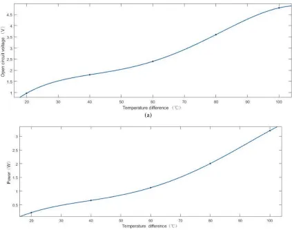
[image:3.612.207.402.498.581.2](a)
[image:4.612.91.514.74.407.2](b)
Figure 4. Variation of (a) open-circuit voltage and (b) power with the temperature.
Voltage Regulator
According to the Seebeck effect, the magnitude of the potential differences is closely related to the magnitude of the temperature difference(TD). The open-circuit voltage changes since the TD dynamically changes. However, the output requires a stable voltage. So a voltage regulator circuit is required to convert changing voltage into a stable one. Considering that most of current low-wattage devices are rated at 5 V, the system selects a high-efficiency synchronous boost converter TPS61027 with a 0.9-6.5V input and a 5V output. The circuit is shown in Fig.5.[3]
[image:4.612.117.492.551.691.2]1 2 1 (3)
3 4 1 (4)
The way to adjust the output voltage is available. The relationship of resistors R1, R2 determines the magnitude of the minimum input voltage VBAT, where R2 should be less than 500kΩ. VBAT is given by Eq.3. The relationship of resistors R3 and R4 determines the magnitude of the output voltage, where R4 should be less than 500kΩ, and the output voltage can be given by Eq.4.[3]
Charging and Discharging Protector
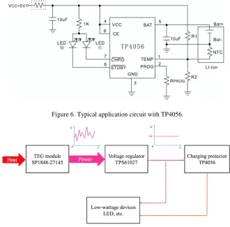
[image:5.612.137.467.281.606.2]Considering that the power generation rate may be higher than the equipment power consumption rate, the system requires batteries along with their charge and discharge protection circuits. This system selects a single-cell lithium-ion battery charger TP4056. Its characteristics include battery positive and negative reverse connection protection, battery temperature detection, etc. It is suitable for power storage protection of small TEG systems. The typical application circuit is shown in Fig.6[4]. Therefore, the TEG system can be specified in Fig.7.
[image:5.612.149.458.283.436.2]Figure 6. Typical application circuit with TP4056.
Figure 7. A specified TEG system.
TD Model Simulation
of the material, determined by the properties of the material itself. dZ is the direction of the vertical plane. [5]
!"
!# $ %
!
!&' (5)
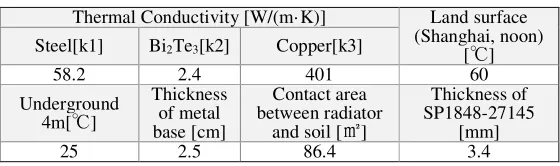
[image:6.612.162.446.208.359.2]Heat Conduction Model. It is assumed that the TEG device is installed on the metal base of the street lamp, and the copper radiator pipe fin is adhered to the cold surface of the TEG module by the thermal conductive grease to expand the contact area with the soil. Considering the series-parallel connection of the TEG modules, the actual contact area between the thermoelectric chips and the metal base is about 0.9 ㎡. Fig.8 is a sketch of the model. The related parameters can be obtained by consulting the data, as is shown in Table.4.[6] Figure 8. Heat flow and physical model of the system. Table 4. Related parameters required to the model. Thermal Conductivity [W/(m· K)] Land surface (Shanghai, noon) [℃] Steel[k1] Bi2Te3[k2] Copper[k3] 58.2 2.4 401 60 Underground 4m[℃] Thickness of metal base [cm] Contact area between radiator and soil [㎡] Thickness of SP1848-27145 [mm] 25 2.5 86.4 3.4 After the steady state is reached, the temperatures of a and b are Ta and Tb respectively, and the heat flows should be equal. Eq.6,7,8,9,10 can be derived from 3.4.1. λ(t) is the soil thermal conductivity changing with temperature and ∆t(Z) is TD changing with soil depth. Therefore, Ta=54.50 and Tb=36.30 are obtained by Monte Carlo simulation with MATLAB. (#))*→, -1 ∗ ∑(4 .50 1. 2 (6)
,→7 -2 ∗ ∑(4 .5 2. 9:1 8 (7)
7→;<=>?! ,→7 (8)
[image:6.612.166.446.415.498.2]Figure 9. Variation of TD with soil depth.
7→;<=>?! -3 ∗ ∑(4 . 5: 81 @ A B ∗ ̅ ∗ ∆B E E: (10)
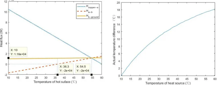
The temperature change process at both ends of TEG module can be simulated with MATLAB, as is shown in Fig.10(a). From the intersection of the Ha→b curve and the x-axis, the temperature of the cold surface is 36.3 ℃. From the intersection of the Ha→b curve and the Hsteel→a curve, the temperature of the hot surface is 54.5 ℃. At this time, the heat flow rates of steel→a, a→b, and b→ ground are equal. The heat transfer model reached equilibrium and TD remained constant, so the actual TD across the generator chip was approximately 18.2 °C in this condition. Based on this model, the relationship between land surface temperature and actual TD can be obtained,as in Fig.10(b).
Figure 10. (a) Variation of heat flux with hot surface temperature (b)Variation of actual TD with heat source temperature.
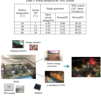
[image:7.612.116.496.389.539.2] [image:7.612.203.406.581.700.2]The Application of the Model. The surface temperature of Guangzhou and other places is obtained by checking the information [7], as illustrated in Fig.11. Derived from Fig.4 and Fig.10, power produced by a land surface - underground TEG system is listed in Table 5.
Table 5. Power produced by TEG system.
Surface temperature
[℃]
Actual TD [℃]
Single generator
TEG system (1㎡, about 224 pieces) Open
circuit voltage[V]
Power[W] Power[W]
30 7 0.43 0.09 20.16
40 11 0.55 0.12 26.88
50 14 0.82 0.18 40.32
60 18 0.93 0.22 49.28
Figure 12. A solid model to verify the TEG system.
The surface - underground TD persists, so the system can achieve all-weather power generation and abundant power sources. It can be seen that although the power of a single TEG chip is very low, when hundreds of TEG chips are connected in series to form a TEG matrix, the power is considerable.
The Production of a Solid Model
The model uses TEG chips in series to simulate the actual matrix. The hot surface is placed with hot water, the cold surface is evenly coated with a thermal grease sticking heat sink and the fan is used to accelerate the heat dissipation, simulating the surface-underground TD. It is generating electric energy as a power source for the entire model, and the LED lamp is a low-wattage electric device. The model integrates the voltage regulator and the battery on a circuit board, and is equipped with a push button switch, a USB interface, etc. to facilitate control and power output. It can be seen from the LED digital tube voltmeter that the regulated output of the TEG system is 5.1V, indicating that the system is feasible.
Conclusion
Acknowledgement
This research was financially supported by(1)Research on Intelligent Control Algorithm of Super High-rise Complex Multi-Energy Air Conditioning System (2)Jiangsu Provincial Housing and Urban-Rural Construction Department - Program on the Next-Generation Smart Green Building.
References
[1] Zeng Hui, Zeng Qi. Seebeck effect and its application [J]. Journal of Jiaying University(Natural Science), 2004(3): 52-54.
[2] Xu Zhijian, Xu Hang. Seebeck effect and thermoelectric generation [J]. Journal of Modern Physics Knowledge, 2004(01): 43-44.
[3] TPS6102x 96% Efficient Synchronous Boost Converter Datasheet, Texas Instruments.
[4] TP4056 Datasheet, Xinyuanzhi Electronic Limited, Shenzhen, China.
[5] Xu Tianshun, Liu Fake. Discussion on the basic law of metal heat conduction [J]. Journal of Physics Teaching, 1988(9).
[6] Xu Guoliang, Wang Xiaomo, Wu Tianhua, Chen Weihan. engineering heat transfer, China Electric Power Press, P210, 2011.