2019 International Conference on Information Technology, Electrical and Electronic Engineering (ITEEE 2019) ISBN: 978-1-60595-606-0
A Low Power Analog Front-End of BJT-based Temperature
Sensor for Implanted RFID
Shi-bo FU
1,2, Wan-ang XIAO
1,2,3,*, Ang WANG
1,2,
Li-na YU
1,2and Wan-lin GAO
4,51Institute of Semiconductors, Chinese Academy of Sciences, Beijing 100083, China
2School of Microelectronics, University of Chinese Academy of Sciences, Beijing, 100049, China
3Center of Materials Science and Optoelectronics Engineering, University of Chinese Academy of
Sciences, Beijing 100049, China
4College of Information and Electrical Engineering,
China Agricultural University, Beijing 100083, China
5Key Lab of Agricultural Infromationization Standardization,
Ministry of Agriculture, Beijing 100083, China
*Corresponding author
Keywords: Low power, BJT-based, Transconductance amplifier, Temperature sensor, Implanted RFID
Abstract. In this paper, a low-power analog front-end (AFE) of BJT-based temperature sensor for implanted Radio Frequency Identification (RFID) is designed. Firstly, the architecture of BJT-based temperature sensor is described. Then a low-power bias circuit in the AFE is proposed to reduce the power consumption, and the bipolar core is optimized to improve the inaccuracy of temperature sensor. At last, the simulation is performed and the chip is fabricated in SMIC 0.18μm technology. The current is 2.6μA with a supply voltage of 1.8V and the current is 1μA when the circuit is disabled. The inaccuracy is 0.6°C from 25°C to 45°C. The power supply rejection ratio (PSRR) is 50dB at DC and 37dB at 1MHz respectively.
Introduction
Radio Frequency Identification (RFID) is a technology that realizes non-contact object identification. Implanted RFID combines temperature sensor with RFID technology to monitor animal’s temperature. Since the battery cannot be implanted into the animal body and cannot be replaced, the passive RFID tags are adopted. For the implanted RFID tags with temperature sensnor, the power is a significant parameter [1].
Delay-line-based and ring-oscillator-based temperature sensors can be quite energy-efficient. However, they need two-point calibration to achieve an inaccuracy below ±1°C [2,3]. BJT-based temperature sensor requires only one-point calibration to achieve an inaccuracy below ±0.2°C and draws less than 10 μA [4,5,6].
In this paper, a low-power analog front-end (AFE) of BJT-based sensor for RFID temperature sensing is proposed, which can generate a proportional-to-absolute-temperature (PTAT) voltage and a complementary-to-absolute-temperature (CTAT) voltage. Chopper technique and dynamic element matching (DEM) are adopted to reduce the mismatch-related errors. To reduce the power consumption, the gm/ID methodology, the self-biasing scheme and an enable control circuit are used.
In the next part, the architecture is described in detail. Part III describes the design of the analog-end of BJT-based temperture sensor. Simulation results are presented in Part IV. The conclusions are presented in Part V.
Architecture Description
parts, an AFE, an ADC and a scaling module. The AFE generates VBE (CTAT) voltage and ΔVBE (PTAT) voltage. These voltages are processed by the ADC and scaling module, then the temperature Dout can be obtained.
For implanted RFID, the AFE must be energy-efficient. Moreover, the nonlinearity of VBE and
[image:2.595.197.411.209.275.2]ΔVBE must be reduced. To meet the extreme low-power requirements of implanted RFID, the gm/ID methodology and the self-biasing scheme are used to decrease the power consumption of the amplifier in the bias circuit. Moreover, an enable control circuit is added to reduce the power consumption dramatically when measurement is not required. To meet the accuracy of animal temperature sensing, chopping technique and dynamic element matching are adopted.
Figure 1. Block diagram of BJT-based temperature sensor.
Design of the AFE of BJT-based Temperature Sensor
Bias Circuit Design
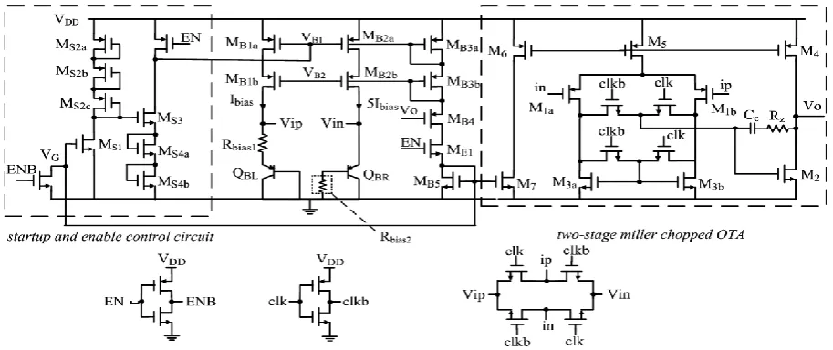
Fig. 2 shows the circuit diagram of the proposed bias circuit. The error caused by curvature of VBE decreases as the temperature dependent of the bias current Ibias increases, so a PTAT bias circuit is used. Two diode-connected PNPs QBL and QBR are biased at 1:5 current ratio. A feedback loop is established around two-stage miller operational transconductance amplifier (OTA). As a result, the bias current Ibias can be expressed as follows:
BE bias
bias1
V I
R
(1) Since a substrate PNP transistor must be biased via its emitter, the resistor Rbias2, whose resistance is one fifth of that of Rbias1, is added to ensure that VBE is independent of the current gain
[image:2.595.77.534.561.753.2]β of the transistor [8]. Cascade current mirror has been used to improve the PSRR and decrease the capacitance load of the OTA, which reduces the performance requirements and the power consumption. The startup circuit ensures that the bias circuit operates as above just described, separating from the unwanted operation point.
Offsets of the OTA introduce spread in VBE, so the chopping technique is used. The amplifier is chopped synchronously with a clock signal clk. The input chopper determines whether the offset voltage is added to positive or negative input port. The output chopper maintains negative feedback. The Miller stage acts as a low-pass filter, which removes the post low-pass filter [9].
To reduce the power consumption, a novel enable control circuit is proposed. When the measurement is not required, EN is invalid (EN=0). The voltage VB1 rises to the supply voltage, while the voltage VG drops to the ground voltage. Moreover, the bias current path from the supply to the ground is cut off. The collective control of EN and its inverted signal ENB dramatically decreases the power consumption and the transition time.
To optimize the power consumption of the OTA, the gm/ID methodology is used [10]. The gm/ID parameter is the ratio between the transconductance gm and the drain current ID. Fig. 3 shows the design flow of the OTA based on the gm/ID methodology. Iteration is used to minimize the power consumption with MATLAB to obtain the sizing parameters. However, the iteration ignores the topology of the OTA, leading to some invalid parameters. Thus the topological constraints are required to filter out the invalid parameters.
[image:3.595.105.496.332.371.2]To further reduce the power consumption, the self-biasing scheme is used. The PTAT bias current is provided to the OTA, so the conventional bias current with the OTA is not needed. This topology reduces the power consumption and die size.
Figure 3. Design flow of the OTA based on the gm/ID methodology.
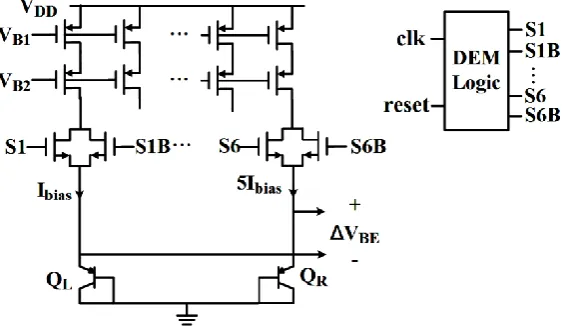
Bipolar Core Design
[image:3.595.165.451.472.635.2]As shown in Fig. 4, these temperature-dependent voltages VBE and ΔVBE can be generated by biasing two identical PNPs at 1:5 current ratio. However, mismatches between these two current sources limit the 1:5 current ratio, which impacts the accuracy of ΔVBE. Therefore, DEM is required to average out these mismatches [9].
Figure 4. Circuit diagram of the bipolar core.
Simulation
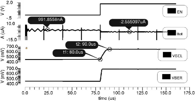
Fig. 5 shows the transient simulation results at 27°C when the supply circuit voltage is 1.8V and the chopping frequency is set to 25kHz. When the enable signal EN is invalid (EN=0V), the current is less than 1μA. When EN changes from 0 to 1.8V at 80us, VBEL, the base-emitter voltage of QL,
Figure 5. Transient response of the AFE.
Fig. 6(a) shows the temperature characteristics of the CTAT voltage VBEL and the PTAT voltage
ΔVBE. VBEL is linear, while ΔVBE is slightly nonlinear. Thus the temperature errors are mainly caused by the nonlinearity of ΔVBE. As shown in Fig. 6(b), linear fitting is used to obtain the ideal temperature curve. To further evaluate the temperature characteristics of ΔVBE, the inaccuracy is defined as Max(Vout,actual-Vout,ideal)*ΔT/ΔVout, where Vout,actual and Vout,ideal are the actual and ideal voltage of ΔVBE, ΔT is the temperature range and ΔVout is the range of ΔVBE. After calculation, the inaccuracy is about 0.6°C.
Figure 6. (a)The temperature characteristics of the CTAT and PTAT voltages.(b) The linear fitting curve.
[image:4.595.112.489.364.498.2]As shown in Fig. 7, the PSRR is about 50dB at DC and 37dB at 1MHz respectively, which shows a good rejection of the fluctuation of the power supply.
Figure 7. PSRR of the AFE.
Conclusions
[image:4.595.177.432.567.717.2]current is 1μA when the circuit is disabled. The temperature characteristics of the CTAT and PTAT voltage are almost linear. The inaccuracy of the PTAT voltage is about 0.6°C from 25°C to 45°C. The PSRR is about 50dB at 1Hz and 37dB at 1MHz respectively.
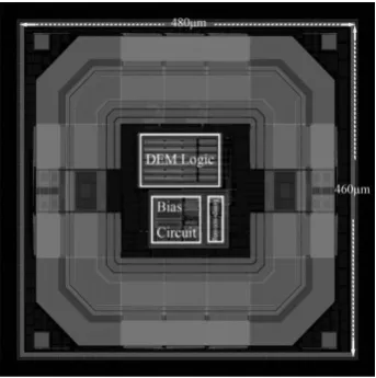
Figure 8. Layout of the AFE.
References
[1] Z. Xiao, X. T, S. Chen, Z. Zhang, H. Zhang, J. Wang, Y. Huang, P. Zhang, L. Zheng, H. Min, An Implantable RFID Sensor Tag toward Continuous Glucose Monitoring, IEEE Journal of Biomedical and Health Informatics. 19(2015), 910-919.
[2] X. Wang, P.H.P. Wang, Y. Cao, P.P. Mercier, A 0.6V 75nW All-CMOS Temperature Sensor with 1.67m°C/mV Supply Sensitivity, IEEE Transactions on Circuits & Systems I Regular Papers. 64(2017), 2274-2283.
[3] A. Vaz, A. Ubarretxena, I. Zalbide, D. Pardo, H. Solar, A. Gracia-Alonso, R. Berenguer, Full Passive UHF Tag With a Temperature Sensor Suitable for Human Body Temperature Monitoring, IEEE Transactions on Circuits & System II Express Briefs. 57(2010), 95-99.
[4] B. Yousefzadeh, S.H. Shalmany, K.A.A Makinwa, A BJT-Based Temperature-to-Digital Converter With ±60mK (3σ) Inaccuracy From −55 °C to +125 °C in 0.16-μm CMOS, IEEE Journal of Solid-State Circuits. 52(2017), 1044-1052.
[5] K. Souri, Y. Chae, K.A.A Makinwa, A CMOS Temperature Sensor With a Voltage-Calibrated Inaccuracy of ±0.15°C (3σ) From -55°C to 125 °C, IEEE Journal of Solid-State Circuits. 48(2013), 292-301.
[6] M.K Law, S. Lu, T. Wu, A. Bermak, P. Mak, R.P. Martins, A 1.1 μW CMOS Smart Temperature Sensor with an Inaccuracy of ±0.2°C (3σ) for Clinical Temperature Monitoring, IEEE Sensors Journal. 16(2016), 2272-2281.
[7] M.A.P Pertijs, K.A.A Makinwa, J.H. Huijsing, A CMOS Smart Temperature Sensor With a 3σ Inaccuracy of ±0.1°C From -55°C to 125°C, IEEE Journal of Solid-State Circuits. 40(2005), 2805-2815.
[8] M.A.P Pertijs, J.H Huijsing, Precision Temperature Sensors in CMOS Technology, Springer, Netherland, 2006.
[9] A. Bakker, K. Thiele, J.H. Huijsing, A CMOS Nested-Chopper Instrumentation Amplifier with 100-nV Offset, IEEE Journal of Solid-State Circuits. 35(2000), 1877-1883.
[10]P. Jespers, The gm/ID Methodology, a sizing tool for low-voltage analog CMOS Circuits,