R E S E A R C H A R T I C L E
Open Access
Finite Element Analysis of porously
punched prosthetic short stem virtually
designed for simulative uncemented Hip
Arthroplasty
Matthew Jian-Qiao Peng
1, Hai-Yan Chen
1, Yong Hu
2, XiangYang Ju
3and Bo Bai
1*Abstract
Background:There is no universal hip implant suitably fills all femoral types, whether prostheses of porous short-stem suitable for Hip Arthroplasty is to be measured scientifically.
Methods:Ten specimens of femurs scanned by CT were input onto Mimics to rebuild 3D models; their *stl format dataset were imported into Geomagic-Studio for simulative osteotomy; the generated *.igs dataset were interacted by UG to fit solid models; the prosthesis were obtained by the same way from patients, and bored by punching bears designed by Pro-E virtually; cements between femora and prosthesis were extracted by deleting prosthesis; in HyperMesh, all compartments were assembled onto four artificial joint style as: (a) cemented long-stem prosthesis; (b) porous long-stem prosthesis; (c) cemented short-stem prosthesis; (d) porous short-stem prosthesis. Then, these numerical models of Finite Element Analysis were exported to AnSys for numerical solution.
Results:Observed whatever from femur or prosthesis or combinational femora-prostheses,“Kruskal-Wallis”valuep> 0.05 demonstrates that displacement of (d)≈(a)≈(b)≈(c) shows nothing different significantly by comparison with 600 N load. If stresses are tested upon prosthesis, (d)≈(a)≈(b)≈(c) is also displayed; if upon femora, (d)≈(a)≈(b) < (c) is suggested; if upon integral joint, (d)≈(a) < (b) < (c) is presented.
Conclusions:Mechanically, these four sorts of artificial joint replacement are stabilized in quantity. Cemented short-stem prostheses present the biggest stress, while porous short-stem & cemented long-stem designs are equivalently better than porous long-stem prostheses and alternatives for femoral-head replacement. The preferred design of those two depends on clinical conditions. The cemented long-stem is favorable for inactive elders with osteoporosis, and porously punched cementless short-stem design is suitable for patients with osteoporosis, while the porously punched cementless short-stem is favorable for those with a cement allergy. Clinically, the strength of this study is to enable preoperative strategy to provide acute correction and decrease procedure time.
Keywords:Uncemented short stem, Porously punched prosthesis, Artificial joint replacement, Contact stress, Finite Element Analysis
* Correspondence:[email protected]
1Guangdong Orthopedics Implantation key Lab, Orthopedics Department of 1st Affiliated Hospital, Guangzhou Medical University, 151 YanJiangXi Rd, Guangzhou 510120, China
Full list of author information is available at the end of the article
Background
A meticulous preoperative strategy is of paramount im-portance before performing a complex operation that could employ multiple available reconstructive techniques. Additionally, proper modular implants of artificial pros-theses in terms of type and length must be selected prior to hip surgery. There are various procedures for treating femoral neck fractures. For fresh fracture without disloca-tion, internal fixation is preferable. For elderly patients with osteoarthritis or rheumatoid arthritis, Hip Arthro-plasty (HA) is a prevalent approach to achieve function restoration of degenerative joint diseases in the twentieth century. However, there is no universal hip implant to suitably treat all femoral types, and appropriate design is demanded that could prevent complications from the implant’s geometric mismatch. The previous literature indicates that joint fracture is quite likely to occur if there are high stresses in the fixation areas [1, 2], and conven-tional stems have showed disadvantages, such as proximal stress shielding, loss of bone stock, and a risk of fracture [3]. Dennis et al. suggests that cement carries a risk of fatigue failure than bone since more cracks were formed in cement than in bone in this study [4]. Fawzi et al. pos-ited that bone cement material, stem material and shape significantly affect the Total Hip Joint performance, as well as that the stem length has significant effects on resultant Von Mises stresses for bone, stem and cement [5]. Short-stem prostheses were reported primarily to preserve fem-oral bone stock, reduce the amount of osteotomy during femoral preparation and facilitate future revision surgery possibly [6], but there has been doubt that they can main-tain stability, osseointegration and survival of the femoral stem [5]. Walker et al. suggests that the femoral moment of the compressive strain of an uncemented prosthesis is only 30% of that for cemented prostheses [7]. Whiteside et al. declared that cementless short-stem prostheses preserve femoral neck with greater torsional stability while reducing distal migration of the stem [8]. Because unce-mented straight stems have demonstrated excellent long-term results into the third decade, we hypothesize that the stem type or size may affect the value and distribution of mechanical stress, but newly designed short-stem designs need to be critically evaluated. The issues of “Long or short stem?” &“Cementlss or cement stem?” will there-fore be investigated in this study. To realize this aim, first of all, a three-dimensional (3D) femoral model for pre-operative planning is achieved by Reverse Engineering Software that mimicked operative protocol virtually; then, four sorts of simulative stems (Cemented stem of long and short without pore, Cementless stem of long and short with pore) were designed and compared by Finite Element (FE) method mechanically. Finally, clinical contention concerning the bio-mechanism is discussed in the conclusion.
Methods
Experimental material
The facilities needed are listed as: 10 sets of specimens (female patients aged 20 ~ 40 yrs) of femora with pros-theses from our hospital (in accordance with standards of Guangzhou Medical University Committee (#2014A0 20215035) and with the 1964 Helsinki declaration) scanned by Computed Tomography(CT, Toshiba, Japan), medical Image Processor Mimics (Materialise, Leuvan, Belgium), Reverse Engineering software Geomagic-Studio-12 (3D Systems, Rock Hill, USA), interactive Computer Aided Design (CAD) / Computer Aided Manufacturing (CAM) package UG-8.0 (Siemens, Germany), 3D drawing processor ProE/Engineer-5 (Parametric Tech Corp, USA), and Finite Element Analysis (FEA) package AnSys-14 (ANSYS, Inc. Pennsylvania, USA), pre-FEA processor Hypermesh-13 (Altair Engineering, USA), and Universal Testing Machine (UTM, Zwick Roell, Germany).
Experimental procedure
Reconstruction of the femoral model
Ten femora scanned by CT in Dicom format were exported to Mimics. The default bony gray value range of 226 ~ 2311 was set to the threshold so that the femur was separated from the proximal femur extracted by “Region Growing”. The“Edit mask”function on the“Mask” mod-ule was then executed to erasure / protract / calculate the 3D model [9], and a proximal femur model of the *.stl for-mat was developed for accurate measurement.
Distal femur developed
The aforementioned 3D model was imported to Reverse Engineering software Geomagic Studio and then faired-up by the function of “Grid doctor”. The osteotomy along the base line of femoral neck was processed by
“Plane section” module so that 1.5 cm medial femoral cortex is remained (Fig. 1a), which was performed through a series of procedures called “Probe curvature” (Fig. 1b)→“Degraded contour”(Fig. 1c)→“Construct sur-face patches”(Fig. 1d)→“Construct grid”(Fig. 1e)→“ Fit-ting surface” (Fig. 1f) etc. A curve contour graph, called Non-uniform rational Basis spline (NURBS) cyrtography, was then fitted (Fig. 1).
Solid model fit
The above acquired cyrtograph models of the femoral shaft were exported to commercially available “ Inter-active CAD/CAM software”, UG-8.0, for further refine-ment. An entity model of solid was conversed by its functions of“Insert→Combine→Fit”, and clicking the
Femoral prostheses preparation
(1).A“Long-stem femoral prosthesis”of 135 mm was obtained (Fig.2b) when patients with femoral head replacement underwent CT and were similarly processed as the aforementioned“Distal femur developed”session.
(2).A“Long-stem femoral porous prosthesis”: a punching-bear with 27 cylinders of 4 mm diameter was created by Pro-E (Fig.2a), and was then imported onto Hypermesh together with the (1)“Long-stem femoral prosthesis”so that this long-stem is punched to be “porous prosthesis”(Fig.2c) through“Boolean calculation”.
(3).A“Short-stem femoral prosthesis”of 100 mm (Fig.2d) was developed after simulatively osteotomized by 35 mm from the (1) “Long-stem femoral
prosthesis”.
(4).A“Short-stem femoral porous prosthesis”with 23 cylinders that had diameters of 4 mm (Fig.2e) was acquired after (3)“Short-stem femoral prosthesis” was punched with a“Boolean calculation”, similarly to procedure of item (2).
Osseous cement preparation
The total hip prostheses were amplified by 2 pixels during the Mimics execution and then extracted by *.stl format. Simulative osteotomy occurred on Geomagic-studio along the break-angle of prosthesis by same direction. The remaining prosthetic stem, which was amplified by 2 voxels, was imported onto UG to fit 3D-solid model. The models were then exported to Hypermesh to remove the original prosthetic stem from the amplified prosthetic stem by Boolean calculation. The virtual model of the bony cement layer with 3 mm-thickness [10] and a cavity are shown in Fig. 2f & 2g.
Fig. 1NURBS kyrtograph fitted for femoral shafts.aSimulative osteotomy.bCurvature detected.cOutline downgraded.dPatch constructed. eGrating constructed.fKyrtograph fitting
[image:3.595.56.539.87.245.2] [image:3.595.58.539.534.715.2]Assemblies of the replacement model
The above models of the femora, prostheses and cement were synthetized in Hypermesh to assemble the following four replacement types: (a) long-stem cemented prosthesis (Fig. 2h), (b) long-stem porous prosthesis (Fig. 2i), (c) stem cemented prosthesis (Fig. 2j), and (d) short-stem porous prosthesis (Fig. 2k).
Joint material assignment
A distal femur can be obtained after removing the space occupied by the prosthetic cemented stem or porous stem by Boolean calculation. The femora and other com-partments were volume-meshed with cell-attribute as-signment. All models of femora, prostheses and cement were exported back into Mimics for materials assign-ment. Then, the elastic modulus was automatically cal-culated. Based on CT gray-scale for bone, the elastic modulus was divided into five uniform scale so that five types of bony materials were assigned (with the mini-mum for inner and maximini-mum for outer) according to a
known formula [such as: Density p= 1017 × Grayvalu-scale - 13.4 (g/cm3), Modulus = 5925 × Density-388.8 (MPa)]. Poisson’s ratio was assumed to be 0.3. The prop-erties of the remaining materials are based on prior studies [11, 12]. In this way, the geometrical 3D FE models of classic stems were obtained.
Loads configuration & boundary constraint
The above grid models are to be imported back to Hypermesh so that a compressive preload of 600 N was applied vertically and applied on the bone structures symmetrically. The degree of freedom on a node basis of
x-y-z direction of Cartesian coordinate was constrained to 0, and translational displacements at the distal nodes of the femur were inhibited (Fig. 3a, 3b & 3c) [13, 14].
Model validation test
There are two ways to validate FE Models, which in-clude the following: (1), Numerous model testing— To compare the present method with previous studies of
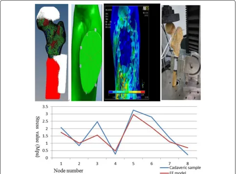
[image:4.595.56.540.345.702.2]similar stress / displacement, and (2), Cadaveric model test-ing — To develop a cadaveric model that resembles FEM in vitro. Its validity will be verified by comparing the similar-ity of outcomes for each experiment based on equal status.
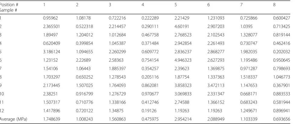
It is assumed that FE model of the femoral neck is resected by a plane horizontally, and the circumference is intercrossed by four lines at 45° angles, forming 8 nodes (8 × 45° = 360°). When 600 N is vertically pressed on each of the corresponding 8 nodes of 12 samples [15] (these 12 samples are for model validation which are different from those 10 sets of spacemen for virtual surgery), the average values of stresses were acquired, as presented in Table 1. On the other hand, strain-foils were attached at relative positions of an intact cadaveric femur corresponding to FE model and mounted to UTM [12] (Fig. 3d). The load-strain curve was observed by recording the strain value when the maximal pres-sure of 600 N was reached. Force values were calcu-lated to form Table 2 with these formulas: Actual-force = 10 × Measured-Actual-force - 6 (Mpa), Stress = Ac-tual-force × Elastic-modulus (here, 7300 Mpa was chosen according to a reference [16]).
Finite element solution
This generated FE model was exported onto AnSys package for computation and analysis, and the peak and distribution yield were measured. The observation index includes (1) Von Mises stress / displacement contours of femur / cement / prosthesis, and (2) Stress / displace-ment contours of the general model.
Results
Observations during model testing Numerous model validations
The current testing outcome was consistent with the validation technique and study conducted by Zhang et al. [17], the comparability of the current result and previous results indicates that our FE model is valid.
Cadaveric model validations
[image:5.595.58.550.98.304.2]Tables 1 and 2 can be consolidated into Table 3 and are interpreted in Fig. 3e. A significance of p > 0.05 from the Independent Sample Test indicates that in vitro ca-daveric testing and the FE models are not significantly
Table 1Stress values for each 8-node of 12 FE samples
Position # Sample #
1 2 3 4 5 6 7 8
1 0.95962 1.08178 0.722216 0.222289 2.21429 1.231093 0.725866 0.600427
2 2.365501 0.522318 2.214457 0.290111 4.60191 2.907203 1.0395 0.713425
3 1.89497 1.204012 1.012684 0.467758 2.768523 2.102543 1.328077 0.819144
4 0.620409 0.399854 1.045387 0.371484 2.942854 2.261493 0.730747 0.462416
5 3.186124 1.094655 2.260299 0.609772 2.836237 2.868277 1.982035 0.202032
6 1.23152 2.22689 2.58363 0.754154 4.946323 2.627293 1.195486 0.950645
7 1.54106 1.06443 1.885397 0.354257 2.39623 1.369875 0.971287 0.798693
8 1.703297 0.650252 1.278543 0.205116 1.87754 1.337363 1.518337 1.046773
9 2.173445 1.507025 1.764093 0.862081 3.858323 3.472113 1.147653 0.367901
10 2.38251 0.916799 1.276729 0.970677 3.069833 2.331347 0.668171 0.883533
11 1.507317 0.710776 1.338166 0.412746 2.74588 1.366152 0.683243 0.581944
12 1.417896 0.720122 1.34875 0.19126 1.19263 1.19263 1.249671 0.896941
[image:5.595.57.540.605.732.2]Average (MPa) 1.748639 1.008243 1.560863 0.475975 2.954214 2.088949 1.103339 0.693656
Table 2Stress values for each 8-node of cadaveric femur
Node # Strain #1 Strain #2 Strain #3 Strain average Absolute value Stress (MPa)
1 250 290 315 285 285 2.0805
2 −110 −120 −115 115 0.8395
3 −325 −350 −337.5 337.5 2.46375
4 −35 −35 −35 −35 35 0.2555
5 425 455 460 446.6667 446.7 3.26091
6 380 385 382.5 382.5 2.79225
7 190 185 187.5 187.5 1.36875
different (they are agreeable to each other), which validates our approach for further simulation and analysis.
Observation of stress distribution Stress of prostheses
As depicted by Fig. 4, generally, the contact stresses of all femoral-head prostheses are concentrated around prosthetic stems equably. For model (a), the pressure crest value is across the edge of femoral-head intersect-ing the prosthetic stem. For style (b), the summit value
is along the middle of prosthetic stem. For style (c), the stress peak appears at the intersection of prosthetic terminus and bony cement. For style (d), the stress apex is located at prosthetic head crossing neck as well as the middle stem. The prostheses are easier to damage from these locations [18].
[image:6.595.54.541.100.150.2]As depicted by Table 4, the mean stress value of each model is as follows: (a) = 46.7682, (b) = 57.5332, (c) = 57.2927, and (d) = 48.8891 (MPa). The variance homogeneity test and analysis demonstrates that these
Table 3Stress comparison on correspond positions of FE model to cadaveric femur
Node # Sample #
1 2 3 4 5 6 7 8
FE model 1.7486 1.0082 1.5609 0.4760 2.9542 2.0889 1.1033 0.6937
Cadaver 2.0805 0.8395 2.4638 0.2555 3.2609 2.7923 1.3688 0.2190
[image:6.595.58.541.304.715.2]four types are indifferent significantly (p= 0.064 > 0.05) according to SPSS-13, which could be simplified as (a) ≈ (b) ≈(c) ≈ (d). However, all of these models meet the mechanical prerequisite of femoral-head replace-ment because the maximum stress of each model is less than the Yield Strength of the titanium alloy, which is 600 ~ 900 MPa.
Stress on femora
By reviewing the Von Mises variation of FEA data, the reaction stresses of femora are distributing equally inferior to femoral trochanter and superior to the constrained position. Additionally, stress peaks disperse around the interface of the prostheses terminus and femur.
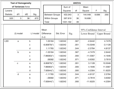
When observed within Table 5, the stress mean-value of each model is as follows: (a) = 10.6316, (b) = 9.5798, (c) = 17.4404, and (d) = 9.5140 (MPa), which are less than the Yield Strength of femur (104 ~ 120 MPa) according to previously published studies [19]. Based on
the factor of variance, all were p< 0.001 < 0.05, which suggests the four styles were significantly different. When analyzed by pairwise comparison between the other three models to determine the biggest stress (c),
p< 0.05 indicated that the cemented short-stem (c) was the most unsuitable type for hip joint implantation [short-ened by (d) < (b) < (a) < (c)]. When further analyzed by pairwise comparison among (a) (b) & (d),p> 0.05 implies that the porous short-stem design (d) was not significantly different from the long-stem (b), and (d) was also indif-ferent from cemented long-stem (a) significantly, which can be simplified as d (d)≈(b)≈(a) < (c).
Stress on integral joints
Based on the Von Mises outcome, the contact stresses of any type of integral joint distributed similarly as the prostheses, the stresses peaked on the prostheses and decreased from the maximum value at the femoral fixation point to the minimum values at the proximal end. By
Table 4Statistics of prosthetic stresses peak (variance homogeneity test & analysis)
ANOVA
Sum of Squares
df
Mean Square
F
Sig.
Between Groups
1158.257
3
386.086
2.643
.064
Within Groups
5259.760
36
146.104
Total 6418.017 39
Test of Homogeneity
of Variances force
Levene
Statistic df1 df2 Sig.
1.929 3 36 .142
N Mean
a 10 46.7682
b 10 57.5332
c 10 59.2927
d 10 48.8891
Total 40 53.1208
(I) model J model
Mean Difference
(I-J) Std.
Error
Sig. Interval
Lower
Bound
Upper
Bound
LSD a b -10.76509 5.40563 .054 -21.7282 .1980
c -12.52459(*) 5.40563 .026 -23.4877 -1.5615
d -2.12098 5.40563 .697 -13.0841 .8422
b a 10.76509 5.40563 .054 -.1980 21.7282
c -1.75950 5.40563 .747 -12.7226 9.2036
d 8.64411 5.40563 .119 -2.3190 19.6072
c a 12.52459(*) 5.40563 .026 1.5615 23.4877
b 1.75950 5.40563 .747 -9.2036 12.7226
d 10.40361 5.40563 .062 -.5595 21.3667
d a 2.12098 5.40563 .697 -8.8422 13.0841
b -8.64411 5.40563 .119 -19.6072 2.3190
c -10.40361 5.40563 .062 -21.3667 .5595
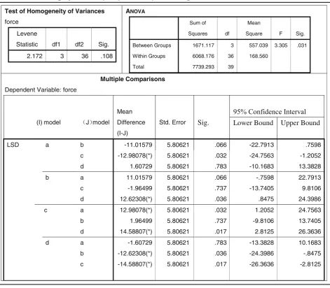
reviewing Table 6, the stress mean-value of each model is as follows: (a) = 47.4895, (b) = 58.5053, (c) = 60.4703, and (d) = 45.8822 (MPa). These values were analyzed by a fac-tor of variance: allp= 0.031 < 0.05, suggesting a significant discrepancy [simply described by (d) < (a) < (b) < (c)]. When analyzed by pairwise comparison,p< 0.05 indicates they are significantly different, but p > 0.05 suggests the difference between (a) v.s. (d) was not significant statisti-cally, which is (d)≈ (a) < (b) < (c). Mechanically, the (a) cemented long-stem and (d) porous short-stem are the least stressed.
Observation of displacement distribution Displacement of femora
Femur displacement implies its magnitude of stability relative to femoral joint. Through observation of Fig. 5, we found that peak displacement of all models was concen-trated near the greater-trochanter adjacent region, which decreases distally in concentric circles. The direction of migration was vertical downward. The displacement mean-value of each model is as follows: (a) = 0.8484,
(b) = 0.8269, (c) = 0.8179, and (d) = 0.7658 (mm); a signifi-cance ofp> 0.05 when analyzed by pairwise comparison suggests the difference is not significant.
Displacement of integral joint
The displacement of integral joint implies its magnitude of fastness relative to the entire femoral joint. By obser-vation of finite element data, we found that the direction of displacement was vertically downwards, the all peak displacements were concentrated on the head of pros-theses and decrease distally in concentric circles. The displacement mean-value of each model was as follows: (a) = 1.0257, (b) = 0.9984, (c) = 0.9915, and (d) = 0.9849 (mm), a significance of p> 0.05 when analyzed by pair-wise comparison suggested the risk of coxa adducta among all joint types was significantly indifferent.
Displacement of prostheses
[image:8.595.61.535.99.468.2]The distribution of prosthetic displacement behaves similarly to that of the integral joint.
Table 5Statistics of femoral stresses peak (pairwise comparison among 4 models)
Test of Homogeneity
of Variancesforce
Levene
Statistic df1 df2 Sig.
.520 3 36 .672
ANOVA
Sum of
Squares df
Mean
Square F Sig.
Between Groups 433.343 3 144.448 8.698 .000
Within Groups 597.819 36 16.606
Total 1031.162 39
(I) model J model
Mean
Difference
(I-J)
Std. Error Sig. Lower Bound Upper Bound
LSD a b 1.05184 1.82242 .567 -2.6442 4.7479
c -6.80879(*) 1.82242 .001 -10.5048 -3.1128
d 1.11765 1.82242 .544 -2.5784 4.8137
b a -1.05184 1.82242 .567 -4.7479 2.6442
c -7.86063(*) 1.82242 .000 -11.5567 -4.1646
d .06582 1.82242 .971 -3.6302 3.7619
c a 6.80879(*) 1.82242 .001 3.1128 10.5048
b 7.86063(*) 1.82242 .000 4.1646 11.5567
d 7.92644(*) 1.82242 .000 4.2304 11.6225
d a -1.11765 1.82242 .544 -4.8137 2.5784
b -.06582 1.82242 .971 -3.7619 3.6302
Discussion
Artificial short stems for uncemented total HA have been alternatively practiced to conventional stem designs. However, there is little biomechanical examination for effects of stem length and stem character on surgical com-plications [20]. To isolate clinical variables, the theoretic test performed by FEA is essential to Mimic ultimate prosthetic geometry prior to actual fabrication because it is rectified to fail practically if a stem fails at this stage. Computational FEM has been extensively employed in predicting optimized implants prescribed by surgeons [21]. The strength of FEA carried out by computer aided simulation enables preoperative strategy and decreases procedure time. This experiment of “outside bone and outside body” is also harmless for humans or animals. Our models were not only consistent with predecessors, and they were also similar to cadaveric data. These
punched prostheses were designed virtually with mech-anic compatibility and bio-compatibility for clinical appli-cation. These structures may induce bony ingrowth at the porous interface, which is beneficial to bioactivity. Additionally, all the four femoral stems were anatomically tailored to individualize the femoral structure towards stress and displacement.
[image:9.595.63.535.96.508.2]Displacement is an indicator for determining the sta-bility of newly designed stems. Several factors such as implant shape, stem size, bone-implant gap are accounted for micromotion [22]. Regarding cemented stems, fastness between bone and cement relies on pene-tration of the cement upon cortex. The mechanical interlocking between these two constituents is correlated with bony stress surrounding the cement. A Load-transfer mechanism takes place at this interface, and cementing mechanization is driven by friction rather
Table 6Statistics of integral joint stresses peak (pairwise comparison among 4 models)
Test of Homogeneity of Variances
force
Levene
Statistic df1 df2 Sig.
2.172 3 36 .108
ANOVA
Sum of
Squares df
Mean
Square F Sig.
Between Groups 1671.117 3 557.039 3.305 .031
Within Groups 6068.176 36 168.560
Total 7739.293 39
Multiple Comparisons
Dependent Variable: force
(I) model J model
Mean
Difference
(I-J)
Std. Error Sig. Lower Bound Upper Bound
LSD a b -11.01579 5.80621 .066 -22.7913 .7598
c -12.98078(*) 5.80621 .032 -24.7563 -1.2052
d 1.60729 5.80621 .783 -10.1683 13.3828
b a 11.01579 5.80621 .066 -.7598 22.7913
c -1.96499 5.80621 .737 -13.7405 9.8106
d 12.62308(*) 5.80621 .036 .8475 24.3986
c a 12.98078(*) 5.80621 .032 1.2052 24.7563
b 1.96499 5.80621 .737 -9.8106 13.7405
d 14.58807(*) 5.80621 .017 2.8125 26.3636
d a -1.60729 5.80621 .783 -13.3828 10.1683
b -12.62308(*) 5.80621 .036 -24.3986 -.8475
than adhesive properties [23]. Cemented prostheses (a) / (c) achieve primary stability mechanically through locks between cement surrounding the bone and implant, which inhibits distal migration by osseointegration. Cementless prostheses (b) / (d) induce bony ingrowth onto the implant surface, which is biologically referred to as secondary stability. Previous studies indicate that the amount of ongrowth is inversely proportional to the amount of micromotion [24]. With respect to porous stems, Manley et al. reported that uncemented porous prostheses allow for bone ingrowth to achieve rigid fi-xations, but the shortcoming of osteolysis influences their long-term stability [25]. These results conflict with Ellison’s view that the “porous stem encourages stable fixation and securely seals joint space by preventing mi-gration”[26]. At this time, we numerically demonstrated the degree of stabilization using the analytical FE ap-proach. When double tested statistically by SPSS,
p> 0.05 for displacements of (a) / (b) / (c) / (d) implied
that these four sorts of stems attain fastened equally after installation.
Pre-stress to bones can be created in femoral canal by internal fixation, which is probably susceptible to failure based on the stresses distribution onto the modular junctions of the implants. Suppose the joint with implant is loaded in equivalency. In terms of contact stresses upon femoral-head prostheses, the statistical dataset [(d)≈(a)≈(b)≈(c) in simplification] demonstrates these four types behave similarly in quantitation; In terms of the stresses upon femurs, the statistical data in order of (d) ≈ (a) ≈ (b) < (c) demonstrates that type (c), the
“Cemented short-stem”, performs the worst; In terms of the stresses on the whole joints, the statistical data sup-porting (d) ≈ (a) < (b) < (c) demonstrates that type (b),
“Porous long-stem”, is also not a good option. In sequence, the least stress (d)≈ (a) supports that type (a)
“Cemented long-stem” and (d) “Porous short-stem” dis-tribute optimal loads and can be used in practice. There
[image:10.595.65.541.84.477.2]are several possible mechanical reasons for these out-comes: (1), If designed with cemented, when considering the stem, because quota-stress is shared by wider area when length is extended, stress on long-stem is less than short-stem. When considering the cement, which is the weakest material and has a higher risk of fatigue failure at the cement-bone interface, maximum stress on the cement increases when the length increases, a longer dis-tance between the loading-point and fixation-point in-duces larger bending-stress at the distal end. (2), If designed with uncemented, long-stem appears to be superior to short-stem by the reasoning in (1), but this statement is actually controversial as follows: short-stems enable sufficient space for complete osseous ingrowth, preserving greater stability, this design also confers higher resistance from torsional forces and has a lower risk of peri-prosthetic fracture than long-stems. With respect to the survival rate (99 ~ 100% for 10 years) reported by McLaughlin et al. [23, 27], short stem designs are sug-gested as alternative to longer stem designs. (3), If de-signed with“punched”, porous stems provide meaningful structural support. The porous nature enables bony in-growth, and the new bones can handle load and enlarge surface area [28]. As a result, stress on cementless-stem with pore is sequentially less than cemented-stem with-out porous coating [4, 29]. Therefore, short-stemmed punched-prostheses are generally thought to facilitate sur-gery compared to long-stemmed cemented-prostheses.
However,“the least” doesn’t mean“the best”and “ min-imal” isn’t equal to “optimal”, because minimal stress doesn’t guarantee the best choice for a clinical trial. The prostheses inserted into the femoral cavity might change the normal stresses distributions. Stress can be spread to the distal femur via intramedullary prosthesis despite its support by the proximal femur, which leads to stress-shielding, affecting the osseous integrity and resistance [30]. Longer stems are believed to give higher stresses at the femur and then be capable of reducing stress shielding problems, whereas shorter stems decrease the load-transfer to the cortical bone and encourages stress shield-ing and bone resorption, which results in failure of the prosthesis sometimes [31]. Chen WP et al. revealed that less stress shielding occurs in those femurs with fully cemented fixation [32]. For an uncemented short stem, even if Maier reported it is curved stems but not straight stems that cause cortical hypertrophy, there is no signifi-cant effect on the clinical outcome at early follow-up [33]. Regarding porous prostheses, Ellison et al. provides evi-dence that these prostheses do not cause stress shielding in 14-year follow-up [26]. As another result, the module that achieves the minimum stress-shielding is the cementless prosthesis, due to poor results of cemented components after revision surgery, short-stem of porously punched uncemented prosthesis has become more popular.
Conclusion
In summary, this study proposes long v.s. short stems of cementless v.s. cement in 3D models providing statistical analysis in comparison with conventional methods. The data support the hypothesis that stresses and distribu-tions of prosthetic stems are various from types or sizes: Mechanically, displacement outcome has equal fastness for these four types of femoral stems, and the mechanic result is positive for both cemented long-stem and unce-mented short-stem designs. Clinically, the ceunce-mented long-stem design is suitable for patients with osteopor-osis, while the porously punched cementless short-stem is preferable for those with easy osseo-ingrowth or with cement allergy. Functionally, the advantage of the punched-prosthesis designed by virtual computation without a cement matrix is that it could be immobilized by the flesh bone structure growing inside the prosthesis orifices. Not only is the contract stress reduced, compli-cations in cement are also avoidable, and this approach should be recommended as reasonable alternative for femoral-head replacement.
Abbreviations
3D:Three Dimensional; CAD: Computer Aided Design; CAM: Computer Aided Manufacturing; CT: Computed Tomography; FE: Finite Element; FEA: Finite Element Analysis; HA: Hip Arthroplasty; THA: Total Hip Arthroplasty
Acknowledgements
Thanks for detailed comments from Dr. Nagano & Dr. Rahmatullah. Thanks for Dr. Liu Yueju’s direction for correction requested. Thanks a lot for additional chance given by Dr. James Mockridge!
Funding
This work is supported by: 1.“Guangdong Dept. of Science Technology” granted project (#2014A020215035); 2. Guangzhou Dept. of Education granted project:“High Educational 12-5 Plan”project (#1201420813); 3. Innovation and Technology Fund of Hong Kong / Guangdong Collaborative Plan (#20170506).
Availability of data and materials
Data and materials are provide upon requested, please contact author if applied.
Authors’contributions
Ethics approval and consent to participate
Informed consent was obtained from all participants included in the study. All procedures performed in studies involving human participants were in accordance with the ethical standards of Guangzhou Medical University Committee (#2014A020215035) and with the 1964 Helsinki declaration and its later amendments or comparable ethical standards.
Consent for publication Not applicable.
Competing interests
No author associated with this paper has disclosed any potential or pertinent conflicts which may be perceived to have impending conflict with this work.
Publisher’s Note
Springer Nature remains neutral with regard to jurisdictional claims in published maps and institutional affiliations.
Author details 1
Guangdong Orthopedics Implantation key Lab, Orthopedics Department of 1st Affiliated Hospital, Guangzhou Medical University, 151 YanJiangXi Rd, Guangzhou 510120, China.2Neural Electrophysiology Lab, University of Hong Kong, Room 501, Haking Wong Building, Pokfulam Road, Pok Fu Lam, Hong Kong.3Clinical Physics & Bioengineering Department, University of Glasgow, 378 Sauchiehall St., Glasgow G2 3JZ, UK.
Received: 2 January 2017 Accepted: 29 June 2017
References
1. Gillies RM, Morberg PH, Bruce WJ, Turnbull A, Walsh WR. The influence of design parameters on cortical strain distribution of a cement less titanium femoral stem. Med Eng Phys. 2002;24:109–14.
2. Kim SC, Lim YW, Jo WL, et al. Surgical accuracy, function, and quality of life of simultaneous versus staged bilateral Total hip Arthroplasty in patients with Osteonecrosis of the femoral head. BMC Musculoskeletal Disorders 2017;18:266.
3. Yerasimides JG. Use of the Fitmore (R) hip stem bone-preserving system for the minimally invasive anterior-supine approach in hip replacement. Am J Orthop (Belle Mead NJ). 2010;39:13–6.
4. Janssen D, Mann KA, Verdonschot N. Finite element simulation of cement-bone interface micromechanics; a comparison to experimental results. J Orthop Res. 2009;27(10):1312–8.
5. Fawzi F, Jassir A, Fouad H, Alothman OY. In vitro assessment of Function Graded (FG) artificial Hip joint stem in terms of bone/cement stresses: 3D Finite Element (FE) study. Biomed Eng Online. 2013;12:5. 1–17
6. Kim YH, Park JW, Kim JS. Is diaphyseal stem fixation necessary for primary total hip arthroplasty in patients with osteoporotic bone (Class C bone)? J Arthroplast. 2013;28(1):139–46.
7. Walker PS, Schneeweis D, Murphy S. Strains and micro motions of press-fit femoral stem prostheses. J Biomech. 1987;20:693–702.
8. Whiteside LA, White SE, McCarthy DS. Effect of neck resection on torsional stability of cementless total hip replacement. Am J Orthop (Belle Mead NJ). 1995;24:766–70.
9. Peng MJ, Hu Y, Ju X, Cai DZ. Clinical Significance Of Creative 3D-Image Fusion Across [CT+MR] Modalities Based On Approach Of Characteristic Co-Registration. J Med Imaging Health Inf. 2016;6(6):e71–7.
10. Joshi RP, Efekhar NS, McMahon DJ, Nercessian OA. Osteolysis afer Charnley primary low-friction arthroplasty. A comparison of two matched paired groups. J Bone Joint Surg. 1998;80(4):585–90.
11. Senalp AZ, Kayabasi O, Kurtaran H. Static, dynamic and fatigue behavior of newly designed stem shapes for hip prosthesis using finite element analysis. Mater Des. 2007;28(5):1577–83.
12. Joshi MG, Advani SG, Miller F, Santare MH. Analysis of a femoral hip prosthesis designed to reduce stress shielding. J Biomech. 2000;33(12):1655–62. 13. Kayabasi O, Ekici B. Te effects of static, dynamic and fatigue behavior on
three-dimensional shape optimization of hip prosthesis by fnite element method. Mater Des. 2007;28(8):2269–77.
14. Viceconti M, Muccini R, Bernakiewicz M, Baleani M, Cristofolini L. Large-sliding contact elements accurately predict levels of bone-implant micromotion relevant to osseointegration. J Biomech. 2000;33(12):1611–8.
15. Ramos A, Simoes J. Tetrahedral versus hexahedral fnite elements in numerical modelling of the proximal femur. Med Eng Phys. 2006;28(9):916–24. 16. Reggiani B, Cristofolini L, Varini E, Viceconti M. Predicting the subject-specifc
primary stability of cementless implants during pre-operative planning: preliminary validation of subject-specifc fnite-element models. J Biomech. 2007;40(11):2552–8.
17. Zhang GD, Liao WJ, Tao SX. Exploration for Material Assignment and Effectiveness Validation of femoral neck FEA. J Tissue Eng Reach. 2009; 52(3):10263–8.
18. Pitto RP, Hayward A, Walker C, et al. Femoral bone density changes after total hip arthroplasty with uncemented taper-design stem: a five year follow-up study. Int Orthop. 2010;34:783–7.
19. Balasubramaniam U, Dowsey M, Ma F, et al. Functional and clinical outcomes following anterior hip replacement: a 5-year comparative study versus posterior approach. ANZ J Surg. 2016;86:589–93.
20. Kang KT, Koh YG, Son J, et al. Measuring the effect of femoral malrotation on knee joint biomechanics for total knee arthroplasty using computational simulation. Bone Joint Res. 2016;5:552–9.
21. Moussa ME, Esposito CI, Elpers ME, et al. Hip Dislocation Increases Roughness of Oxidized Zirconium Femoral Heads in Total Hip Arthroplasty: An Analysis of 59 Retrievals. J Arthroplast. 2015;30(4):713–7.
22. Viceconti M, Brusi G, Pancanti A, Cristofolini L. Primary stability of an anatomical cementless hip stem: a statistical analysis. J Biomech. 2006;39(7):1169–79. 23. McLaughlin JR, Lee KR. Cementless total hip replacement using
second-generation components: a 12- to 16-year follow-up. J Bone Joint Surg Br. 2010;92:1636–41.
24. Janssen D, Mann KA, Verdonschot N. Micromechanical modeling of the cement-bone interface: the effect of friction, morphology and material properties on the micromechanical response. J Biomech. 2008;41(15):3158–63. 25. Manley MT, D’Antonio JA, Capello WN, Edidin AA. Osteolysis: a disease of
access to fixation interfaces. Clin Orthop Relat Res. 2002;405:129–37. 26. Ellison B, Cheney NA, Berend KR, Lombardi AV, Mallory TH. Minimal stress
shielding with a Mallory-Head titanium femoral stem with proximal porous coating in total hip arthroplasty. J Orthop Surg Res. 2009;4:42.
27. Sariali E, Mouttet A, Mordasini P, Catonne Y. High 10-year survival rate with an anatomic cementless stem (SPS). Clin Orthop Relat Res. 2012;470:1941–9. 28. Chen YL, Lin T, Liu A, et al. Does hydroxyapatite coating have no advantage over porous coating in primary total hip arthroplasty? A meta-analysis. Clin Orthop Relat Res. 2015;10:21.
29. Varitimidis SE, Dimitroulias AP, Karachalios TS, Dailiana ZH. Konstantinos N Malizos Outcome after tantalum rod implantation for treatment of femoral head osteonecrosis 26 hips followed for an average of 3 years. Acta Orthop. 2009;80(1):20–5.
30. Oba M, Inaba Y, Kobayashi N, et al. Effect of femoral canal shape on mechanical stress distribution and adaptive bone remodelling around a cementless tapered-wedge stem. Bone Joint Res. 2016;5:362–9.
31. Huiskes R, Weinans H, Dalstra M. Adaptive bone remodelling and biomechanical design considerations for noncemented total hip arthroplasty. Orthopedics. 1989;12:1255–67.
32. Chen WP, Tai CL, Lee MS, Lee PC, Liu CP, Chun-Hsiung Shih H. Comparison of stress shielding among different cement fixation modes of femoral stem in total Hip arthroplasty–a three-dimensional finite element analysis. J Med Biol Eng. 2004;24:183–7.