2019 International Conference on Computer Science, Communications and Multimedia Engineering (CSCME 2019) ISBN: 978-1-60595-650-3
Effect of Elastic Modulus on Maximum Displacement Response of
Truss Structure
Xin-yang CHEN
1and Zu-ping MENG
2,*1School of Aeronautics and Astronautics, Sun Yat-sen University, P.R. China
2School of Civil Engineering, National Chiao Tung University, Taiwan, P.R. China
*Corresponding author
Keywords: Truss, Elastic modulus, Finite element model, Maximum displacement.
Abstract. Dynamic stress and displacement of truss are directly related to the safety of truss in case of impact loading of the truss structure. Elastic modulus is an important parameter which has an effect on the dynamic stress and displacement in truss structure. Analyzing the effect of elastic modulus on dynamic mechanics can provide the design criterion for truss structure. Here, a 3D simulated method on the basis of finite element model (FEM) was proposed to analyze the dynamic stress and displacement of the truss structure under impact loading. By means of the simulated method, the effect of elastic modulus on the maximum displacement was investigated. Via exporting the corresponding mechanical response, the maximum displacements are plotted in one figure to analyze the effect of elastic modulus on dynamic mechanical response. The maximum displacement could increase when the elastic modulus is raising. Meanwhile, the maximum displacement increases with the elastic modulus in nonlinear pattern.
Introduction
Due to the fact that truss possesses high stiffness per unit mass, it is widely employed in engineering construction. Protecting the object under it, truss structure has no choice but suffering from dynamic impact, and consequently, a yardstick regarding the safety under this situation is supposed to be introduced. As a criterion of truss’ safety, maximum displacement is an crucial parameter for designing truss, which is able to be the reliable yardstick. If maximum displacement is beyond the available standard, it may cause accident during its usage. Thus, the dynamic mechanical response needs to be calculated in order to ensure the safety during the application of the truss structure. The elastic modulus, one of the important design parameters, could be taken into consideration in the paper.
Here, we set up a finite element model (FEM) for discontinuous-section truss system to simulate the dynamic deformation behavior. The FEMs with different elastic modulus were proposed to calculate the dynamic deformation behavior of truss where bars with different elastic modulus drops on the truss. Finally, the effect of elastic modulus on the maximum displacement was discussed.
Finite Element Model
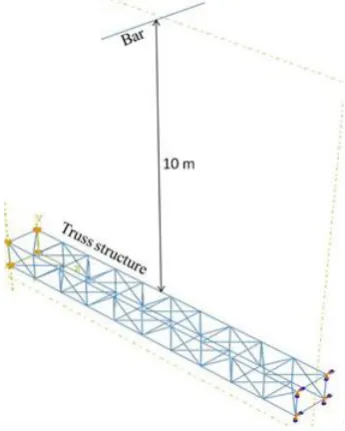
[image:2.595.210.383.358.574.2]FEM which is employed on ABAQUS has been widely adopted to predict the deformation response in truss system [11,12]. In order to research the deformation behavior, a three dimension (3D) FEM was developed here by processing the truss geometry, section type, anslysis step, and boundary conditions. The 3D truss system was entrusted to be deformable. Shear-flexible element was utilized to mesh truss. and the global seeds were uniformly distributed within truss system. The 2-node linear beam element (B31) was chosen to favor convergence as well as improve the computational speed. The 3D FEM used in the paper is shown in Fig. 1. The simply supported boundaries were imposed on both end of the truss. The 10m-length bar with the diameter of 50mm is placed ahead of the truss structure. The length of the truss structure is 3m and the transverse section of truss structure is 1m×1m. The relative height between bar and truss structure is 10m. In this study, the parameters of the truss structure are fixed. Only the elastic modulus of the bar is changeable, which varying from 50GPa to 150 GPa. The different situations for FEMs are given in Table 1. There are respectively 1340 elements and 1351 nodes in the proposed FEM. Due to the impact of bar, a dynamic explicit propramme was employed here.
Figure 1. Finite element model for 3D truss structure.
Table 1. Different elastic modulus for FEM.
Number of FEM 1 2 3 4 5 6
Elastic modulus (GPa) 50 70 90 110 130 150
When the impact process is modeled completely, the primary dynamical deformations, Mises stress, strain and maximum displacement, are exported by picking up data from the output files. Then, the effect of elastic modulus on the maximum displacement could be discussed precisely.
Dynamic Response
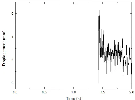
able to be figured out. The first character is after the very moment of the collision between bar and truss, the maximum displacement and stress of the truss are on a clear downward trend and, apparently, the highest point of the curves appear right after the collision. The second character is that both curves show a periodic fluctuation after the collision. Essentially, this event can be regarded as a transient response triggered by instantaneous external force on the middle part of the truss. Consequently, no extra energy is inputted into the truss after the collision and, due to the damping, energy in the truss goes down continuously, which contributes to the declining trend of maximum displacement and stress. Moreover, via observation of the truss’s deformation animation, the truss bends down until the displacement at the middle part reaches the peak. Then, nodes move back to their original spot and continue to move upward. The displacement at two sides of the truss reaches its maximum first following by the middle part reaching its maximum. All nodes repeat this reciprocating motion, which forms the reciprocating motion of the truss. Judging from this fluctuate deformation process, the curves with periodic fluctuation are reasonable.
Figure 2. Variation of stress with time at the most dangerous region.
Figure 3. Variation of displacement with time at the most dangerous region.
Through the previous modeling and calculation results, we can observe the maximum value of stress and displacement under the condition when the elastic modulus of the bar is 90GPa. By using the same method and merely resetting the elastic modulus of the bar to a certain value, we can observe the maximum stress and displacement of the truss structure after impact under different elastic modulus. In order to try to find out a reasonable regularity, we can select five separate cases with the elastic modulus of 50GPa, 70GPa, 90GPa, 110GPa, 130GPa, and 150GPa respectively, and observe the maximum value of stress and displacement for the corresponding case by changing the properties of materials in the present model.
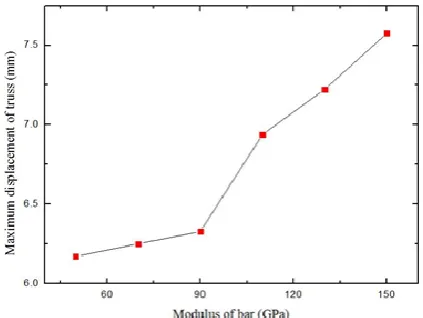
[image:3.595.179.414.450.624.2]corresponding maximum displacement of the truss structure after impact, whose unit is mm. Then we simply convert the data obtained through the calculation to corresponding coordinate points and connect them with polyline to get the graph shown in figure 4. It can be observed that the maximum displacement increases when the elastic modulus increase. When the elastic modulus is comparatively quite small or large, the curve appears a linear condition within a certain range. Even though, it’s obvious that the overall relationship between the maximum displacement and elastic modulus is nonlinear.
Figure 4. Maximum displacement at different modulus of the bar.
Concluding Remarks
In this paper, a three-dimensional model based on FEM is systematically used for dynamical calculation. The dynamical process, i.e., the free fall of the crossbar onto truss system, is modeled by mean of ABAQUS. The corresponding numerical simulation is carried out. A series of finite element analysis methods are established where different elastic modulus were chosen. Ultimately, the effect of elastic modulus on the maximum displacement is discussed, and the following conclusions are obtained:
(1) When the elastic modulus is a constant value, the stress and displacement reach the maximum value at the moment of collision, and then the system experienced gradually weakening while tending to be stable.
(2) Apparently, the maximum displacement increases with the increase of elastic modulus. When the elastic modulus is comparatively quite small or large, the curve appears a linear condition within a certain range. Even though, it’s obvious that the overall relationship between the maximum displacement and elastic modulus is nonlinear.
The above conclusions can be applied to design truss and assess the safety of truss in engineering. Because of the consideration of dynamic impact resistance, the simulated results have the advantage of providing a theoretical basis for practical construction and solving engineering problems in a more comprehensive way.
Acknowledgment
The authors acknowledge Undergraduates Fundamental Research Funds (UFRF) for the finacial support.
References
[2] J.M. Guedes, N. Kikuchi. Preprocessing and post processing for materials based on the homogenization method with adaptive finite element methods. Comput. Methods Appl. Mech. Eng. 83, 143–198 (1990).
[3] J. Yan, G.D. Cheng, S.T. Liu, et al. Comparison of prediction on effective elastic property and shape optimization of truss material with periodic microstructure. Int. J. Mech. Sci. 48, 400–413 (2006).
[4] K. Terada, N. Kikuchi. A class of general algorithms for multiscale analyses of heterogeneous media. Comput. Methods Appl. Mech. Eng. 190, 5427–5464 (2001).
[5] C. Miehe, C.G. Bayreuther. On multiscale FE analyses of heterogeneous structures: From homogenization tomultigrid solvers. Int. J. Numer. Methods Eng. 71, 1135–1180 (2007).
[6] T.Y. Hou, X.H. Wu, Z.Q. Cai. Convergence of a multiscale finite element method for elliptic problems with rapidly oscillating coefficients. Math. Comput. 68, 913–943 (1999).
[7] J.E. Aarnes, S. Krogstad, K.A. Lie. A hierarchical multiscale method for two-phase flow based upon mixed finite elements and nonuniform coarse grids. Multiscale Model. Simul. 2, 337–363 (2006).
[8] J.C. Wu, X.Q. Shi, S.J. Ye, et al. Numerical simulation of land subsidence induced by groundwater overexploitation in Su-Xi-Chang area, China. Environ. Geol. 57, 1409–1421 (2009).
[9] Y. Efendiev, T. Hou, V. Ginting. Multiscale finite element methods for nonlinear problems and their applications. Commun. Math. Sci. 2, 553–589 (2004).
[10] G.M. Verderame, G. De Carlo, P. Ricci, G. Fabbrocino. Cyclic bond behavior of plain bars. Part II: analytical investigation. J Constr Build Mater. 23 (2099): 3512-3522 (2009).
[11] G. Desiderio, M. Latour, G. Rizzano. Modellazione Analitica e FEM del Meccanismo di trasferimento degli sforzi tra Fondello in Acciaio e Calcestruzzo nelle Travi PREM. Proceeding of XIV Convegno ANIDIS "L'Ingegneria Sismica in Italia", Bari, CD-rom; 2011.