2019 International Conference on Computation and Information Science (ICCIS 2019) ISBN: 978-1-60595-644-2
Design of Motor Controller Based on
TMS320F28335 Digital Signal Processing Chip
Cheng Luo, Cheng Yang, Yi Zhao, Xiangqian Nie,
Jinliang Zhang, Xuehuan Jiang and Wei Jian
ABSTRACT
Aiming at the high-power permanent magnet synchronous motor (PMSM), the corresponding motor controller is developed. The vector control strategy with id=0 is adopted to establish the simulation model. The TMS320F28335 digital signal processing chip is used as the core to build the control, protection and drive circuit of the motor controller. Find the law of PID regulation through simulation. After the successful verification of the 0.75kW permanent magnet synchronous motor(PMSM), we carried out the experiment under the high power permanent magnet synchronous motor(PMSM) of 35kW. The simulation and experimental results show that the system has a fast speed response and can realize the control of the motor speed. The protection circuit also shows an effective protection for the motor.
1. INTRODUCTION
As one of the core components of new energy electric vehicles, motor controllers are a vital part. Due to the complicated and diverse working conditions of automobiles, the design of high-power, high-performance and high-efficiency motor controllers will be the main direction of control. Permanent magnet synchronous
motors have received a lot of attention due to the good control performance, high power density and high efficiency [1, 2]. By adopting the control strategy of id=0, it is very effective to control the permanent magnet synchronous motor (PMSM) in a control mode similar to DC motor. We use TMS320F28335 as the main control chip of the motor controller to complete the design and debugging of the control circuit, protection circuit and acquisition circuit, determine which hardware protection functions are needed and whether the test protection can protect the design, realize a high performance The motor controller of the high power, and the control effect of the motor controller is verified by MATLAB simulation and physical verification. The test results show that the scheme has a good effect on improving the efficiency of the electric motor and increasing the cruising range of the electric vehicle.
2. BASIC PRINCIPLE OF VECTOR CONTROL
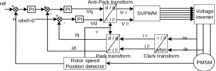
Vector control, also known as FOC (field-oriented) control, was proposed by Siemens AG F. Blaschke et al. The main idea is to transform the stator current of the motor from a three-phase stationary coordinate system to a synchronous rotating coordinate system oriented with a rotor flux linkage, then achieve the decoupling of excitation current and torque current. Since the two a components are spatially perpendicular to each other, they can be controlled independently[3-5].The coordinate transformation simplifies the model and reduces coupling [6],it makes the control of PMSM much easier and convenient just like the DC motor [7]. Figure 1 shows the PMSM vector control block diagram.
PMSM SVPWM Voltage inverter Rotor speed Position detector PI PI
d / q
α/β
Anti-Park transform Vα
Vβ
α/β
a/b/c Clark transform d / q
α/β
[image:2.612.112.490.436.560.2]Park transform ia ib iα iβ PI idref=0 id iq n + -+ + -Vq Vd θ Nref
Figure 1. PMSM vector control block diagram.
3. CONTROLLER HARDWARE CIRCUIT
3.1 Controller Hardware Circuit
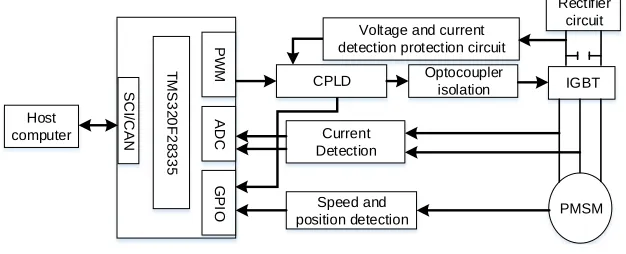
(PMSM), and a host computer. The DSP TMS320F28335 chip with floating-point computing capability is selected for the main control circuit, which has serial communication and CAN communication functions. And the chip has the characteristics of high precision, low cost, low power consumption and high performance [8]. Figure 2 shows the principle block diagram of the PMSM control system.
Through the IGBT inverter and the filter capacitor, the output current is inverted into a three-phase symmetrical AC to drive the permanent magnet synchronous motor (PMSM). The current signal is collected by the Hall current sensor, then biased and amplified by the inverting amplifier, finally, the signal is transmitted to the DSP AD pin The rotor angle and speed signal of the motor output is detected by the resolver, then decoded by the AD2S1210 decoder chip, finally, the data is transmitted to the main control chip IO port. The DSP generates an SVPWM pulse signal through algorithm calculation, then through the optocoupler isolation to drives the IGBT and control the turn-on and turn-off time of the IGBT. After the above processing, the IGBT generates a varying current to control the magnetic field and rotate the motor. The fault signal module is integrated on the IGBT driver board. When the fault signal is issued by the driver board or the voltage and current detection protection circuit, the CPLD will immediately cut off the PWM output and transmit the error signal and fault code to the DSP IO port. The host computer can receive the motor status information and send the control code to the motor through CAN or SCI communication interface.
T M S 3 2 0 F 2 8 3 3 5 SC I/C AN G PI O Host computer AD C PW M Current Detection Speed and
position detection PMSM Rectifier
circuit
IGBT CPLD Optocoupler
[image:3.612.141.454.422.549.2]isolation Voltage and current detection protection circuit
Figure 2. Block diagram of permanent magnet synchronous motor control system.
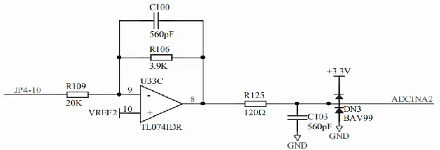
3.2 AD Acquisition Circuit
acquisition pin, so as to prevent chip burning and monitor the voltage within a normal range.
Figure 3. Phase current acquisition circuit.
The voltage output formula is:
) 1 ( 109
106 )
( 2
2
R R V V
V
Uout REF REF in
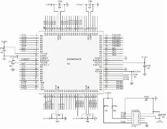
3.3 CPLD Acquisition Circuit
Figure 4. CPLD protection circuit.
3.4 CAN Communication Circuit
Figure 5. CAN communication peripheral circuit.
The CAN communication module of the motor controller is designed according to the automotive-grade circuit, adding anti-interference common mode inductance and dual-channel digital isolation chip, which greatly enhances the anti-interference ability of the signal.
4. SIMULATION
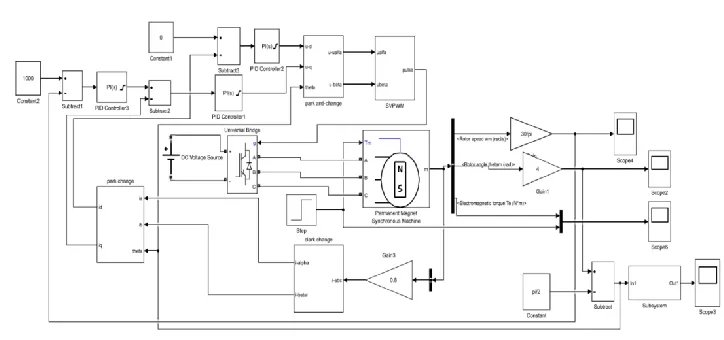
Figure 6. PMSM simulation model by Id=0.
[image:6.612.113.475.378.548.2]speed control module, current control module, coordinate transformation module, SVPWM generation module and signal acquisition module. The motor parameters in the simulation model are shown in Table 1. After setting up the model, PID tuning should be performed on the speed loop and current loop of the motor simulation model. If the PID parameters are not good, the motor will start to oscillate multiple times, suddenly load, and unstable speed, as shown in Figure 7. Through the trial and error method to find the law, the proportion affects the overshoot of the motor speed, and the integral affects the static error of the motor speed. Through repeated trial and error, as well as the proportional and integral adjustments we can perfect control of the motor. The controller experiment will adopt these rules.
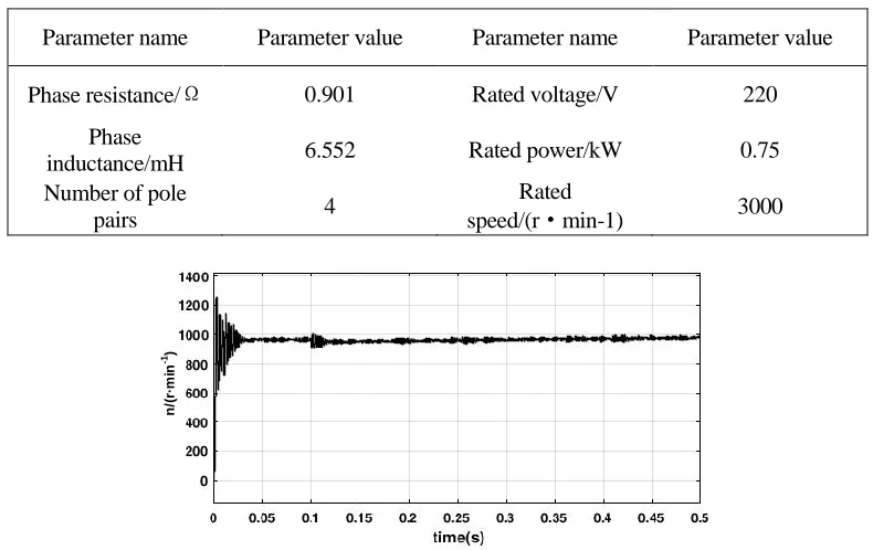
TABLE 1. PMSM PARAMETERS.
Parameter name Parameter value Parameter name Parameter value
Phase resistance/Ω 0.901 Rated voltage/V 220
Phase
inductance/mH 6.552 Rated power/kW 0.75
Number of pole
pairs 4
Rated
speed/(r·min-1) 3000
n
/(
r·
m
in
-1)
n
/(
r·
m
in
[image:8.612.173.421.87.217.2]-1)
Figure 8. n = 1000 speed curve by suitable PID parameter.
From many simulation experiments, the motor can reach the rated speed in less than 0.05s, and there is no overshoot, and the speed curve is relatively stable. When adding the loads at 0.1s, the motor speed is restored to the specified speed for about 0.4s. The speed response curve is shown in Figure 8.
5.CONTROLLER EXPERIMENT
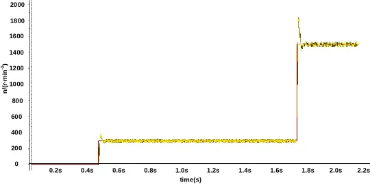
The system's 160V high voltage double closed loop test was performed on a low voltage platform. Observed by the virtual oscilloscope, the speed response is shown as Figure 9, the motor increases the speed to 1500r/min from the stably running state at 300r/min, while in Figure 10, the motor increases the speed to 2100r/min from the stably running state at 1500r/min. It can be seen from the speed image that the motor controller can work very well in variable speed control the motor speed response is extremely fast, and the overspeed adjustment of the speed can also recover quickly.
0.2s 0.4s 0.6s 0.8s 1.0s 1.2s 1.4s 1.6s 1.8s 2.0s 2.2s
time(s) 200
400 600 800 1000 1200 1400 1600 1800 2000
0
n
/(
r·
m
in
-1)
[image:8.612.162.432.515.652.2]0.2s 0.4s 0.6s 0.8s 1.0s 1.2s 1.4s 1.6s 1.8s 2.0s 2.2s time(s)
1000 1100 1200 1300 1400 1500 1600 1700 1800 1900
n
/(
r·
m
in
-1)
[image:9.612.159.433.85.238.2]2000 2100 2200 2300
Figure 10. 160V PMSM speed image.
15s 30s 45s 60s 75s 90s 105s 120s 135s 150s 165s time(s)
180s
n/(
r
·m
i
n
-1)
0 200 400 600 800 1000 1200
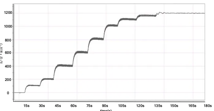
Figure 11. 500V PMSM speed continuous acceleration image.
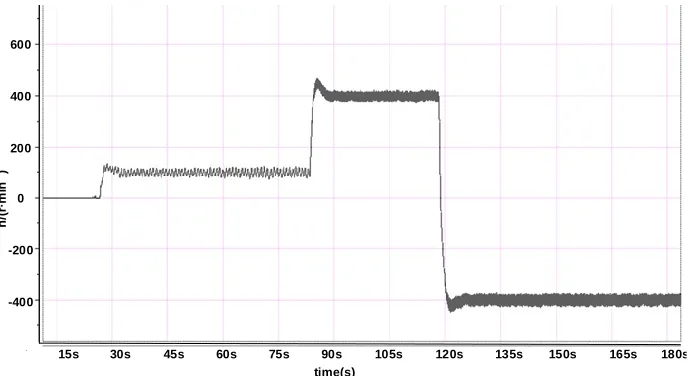
[image:9.612.126.475.270.451.2]-400 -200 0 200 400 600
n
/(
r·
m
in
-1)
15s 30s 45s 60s 75s 90s 105s 120s 135s 150s 165s time(s)
[image:10.612.128.473.83.271.2]180s
Figure 12. 500V PMSM forward and reverse speed image.
In order to test the performance of the motor controller. As shown in Figure 12, the motor controller is turned forward first, the motor quickly reaches the specified speed of 400r/min, and then sets the speed of -400r/min, the motor starts to reverse and quickly reaches the specified speed. We can find that the speed response is very quickly and stable. As well as a little of overshoot.
6. CONCLUSIONS
In this paper, from the design of high-efficiency and high-voltage motor controller, TMSF28335 is used as the main control chip to realize the motor control, the system used the CPLD as the hardware protection of the motor controller, and supplemented by software protection to achieve double protection. With the id=0 and SVPWM speed control strategy, the motor can reach the specified speed under the control of the controller, and the dynamic response speed is fast. In the future, we will add new control strategies in a targeted manner, optimize the motor controller size and weight. Achieve better motor speed and torque control.
ACKNOWLEDGEMENTS
REFERENCES
1. Wang H, Dong X R , Yang X W , et al. 2012. "Research of Permanent Magnet Synchronous Motor Speed Control System Based on DSP," Advanced Materials Research, 2012, 468-471:4. 2. Zhu J, Cheng K W E, Xue X. 2018. "Comparison study of rare-earth-free motors with permanent
magnet motors in EV applications," International Conference on Power Electronics Systems & Applications-smart Mobility. 2018.
3. Shuangfei Zhou. 2017. "Research on Vector Control Strategy of Permanent Magnet Synchronous Motor ," Hubei Automotive Industry Institute, 2017.
4. Shuangfei Zhou, Haibo Huang, Jian Wei. 2017. "Research on Application of Luenberger Observer in Sensorless Control of Permanent Magnet Synchronous Motor," Electrical and Control Applications, 2017, 44(10): 59-62.
5. Minggui Long. 2012. "Vector Control Analysis of Permanent Magnet Synchronous Motor,"
Southwest Jiaotong University, 2012.
6. Baojin Wang. 2010. "Research on driving and control method of permanent magnet synchronous motor for electric vehicle ," Harbin Institute of Technology, 2010.
7. Wei Teng. 2015. "Vector Control of Permanent Magnet Synchronous Motor Based on Resolver,"
Shenyang Ligong University, 2015.
8. Shuping Lü, Zhang Qiang, Wang Wei, Zhang Wei. 2018. "Design of Experimental Teaching Device for Rotating Transformer," Experimental Technology and Management, 2018(08):83-87+96.
9. Luo Cheng, Haibo Huang, Jianwei Mei, et al. 2017. "Comparison of Three Kinds of Speed Modulation Modes of Permanent Magnet Synchronous Motor," Journal of Hubei University of Automotive Technology, 2017(4): 71-74.