Diff u siv e b e n e fi t s of c yli n d e r s i n
f r o n t of a S c h r o e d e r d iff u s e r
Po g s o n , MA, W hi t t a k er, D M, G e h ri n g , GA, C ox, TJ, H u g h e s , RJ a n d
An g u s , JAS
h t t p :// dx. d oi.o r g / 1 0 . 1 1 2 1 / 1 . 3 4 6 3 8 1 7
T i t l e
Diff u siv e b e n efi t s of cyli n d e r s in fr o n t of a S c h r o e d e r
d iff u s e r
A u t h o r s
Po g s o n , MA, W hi t t a k er, D M, G e h r i n g , GA, C ox, TJ, H u g h e s ,
RJ a n d An g u s , JAS
Typ e
Ar ticl e
U RL
T hi s v e r si o n is a v ail a bl e a t :
h t t p :// u sir. s alfo r d . a c . u k /i d/ e p ri n t/ 1 8 5 6 3 /
P u b l i s h e d D a t e
2 0 1 0
U S IR is a d i gi t al c oll e c ti o n of t h e r e s e a r c h o u t p u t of t h e U n iv e r si ty of S alfo r d .
W h e r e c o p y ri g h t p e r m i t s , f ull t e x t m a t e r i al h el d i n t h e r e p o si t o r y is m a d e
f r e ely a v ail a bl e o nli n e a n d c a n b e r e a d , d o w nl o a d e d a n d c o pi e d fo r n o
n-c o m m e r n-ci al p r iv a t e s t u d y o r r e s e a r n-c h p u r p o s e s . Pl e a s e n-c h e n-c k t h e m a n u s n-c ri p t
fo r a n y f u r t h e r c o p y ri g h t r e s t r i c ti o n s .
Diffusive benefits of cylinders in front of a Schroeder diffuser
M. A. Pogson,a兲 D. M. Whittaker, and G. A. Gehring
Department of Physics and Astronomy, University of Sheffield, Sheffield S3 7RH, United Kingdom
T. J. Cox, R. J. Hughes, and J. A. S. Angus
Acoustics Research Centre, University of Salford, Salford M5 4WT, United Kingdom
共Received 17 February 2010; revised 16 June 2010; accepted 18 June 2010兲
A numerical investigation is performed into the diffusive effects of cylinders positioned in front of a Schroeder diffuser. A regular line of cylinders is shown to offer notable improvements to diffusion from a periodic Schroeder device, provided lateral cylinder spacing is incommensurable with the Schroeder period width. Further investigation considers angular dependence and low frequency results in greater detail, as well as the effects on narrowband and modulated Schroeder devices. An optimization procedure is subsequently performed to investigate the effects of an irregular cylinder arrangement, which provides further diffusive benefits. ©2010 Acoustical Society of America.
关DOI: 10.1121/1.3463817兴
PACS number共s兲: 43.55.Br, 43.20.Fn 关LMW兴 Pages: 1149–1154
I. INTRODUCTION
Diffusers are well established in room acoustics as a means to treat problems such as echoes while minimising removal of sound energy.1,2 Good diffusers contain rough-ness over different length scales, with the aim of providing predictable spatial and temporal dispersion of sound across a wide bandwidth. Existing designs are almost exclusively surface-based, with the Schroeder diffuser perhaps being the most renowned example.3 This comprises a sequence of wells whose depths are determined by a pseudo-random number sequence, thus introducing phase shifts to the re-flected sound field.
In this paper the authors consider suspending cylinders in front of a Schroeder diffuser as a means to improve dif-fuser performance. Previous investigation has suggested po-tential benefits of such an arrangement,4including improve-ments to low frequency diffusion and reduction of the effects of ‘plate’ frequencies共where the Schroeder diffuser acts as a flat plate兲 associated with designs based on integer number sequences.1This paper aims to provide a more detailed in-vestigation of such diffusive behavior in order to generate effective and practically viable cylinder arrangements.
The use of cylinders as part of a volumetric diffuser5 contrasts with the majority of interest in the acoustic proper-ties of cylinder arrays, which has concentrated on sound at-tenuation or reduced transmission at selected frequencies,6,7 although arrays of semicylinders have been employed as sur-face diffusers.1,8Past efforts to improve the Schroeder design have included modifying the sequence of well depths, fractal embedding of wells within wells, folding of wells to increase effective depth, and modulating adjacent Schroeder diffusers.1 All these approaches have relied on altering the diffuser itself, whereas the addition of cylinders would allow retrospective modification of existing installations.
Visual appearance is of key importance to the deploy-ment of diffusers, and the use of cylinders may enhance Schroeder devices in this respect. Furthermore, the space be-tween cylinders and the Schroeder diffuser could be used for a drape system to provide variable room acoustics.9 While the addition of cylinders would increase overall diffuser depth, this could be overcome where space is limited by employing a shallower Schroeder diffuser, using sparse cyl-inder arrangements and only positioning cylcyl-inders close to the Schroeder wells. The addition of cylinders is likely to provide advantages over a Schroeder diffuser of the same overall depth, both in terms of improved diffusion and sim-pler construction.
A periodically repeated Schroeder diffuser is the focus of study due to its widespread practical implementation. Our investigation concentrates on the use of a single line of cyl-inders, aiming to address issues associated with periodicity in the Schroeder diffuser. Breaking up periodicity appears to offer the greatest potential for improvement; this is supported by evidence that positioning cylinders in front of a single Schroeder device has little positive effect on diffusion.4
Scattering arrangements are investigated using a bound-ary element method共BEM兲, which is highly accurate and has been validated by practical experiment.1 Cylinders are hung parallel to the extruded diffuser wells, hence by assuming infinite lengths of scattering elements, the problem is re-duced to two dimensions.10
A regular line of cylinders is considered first, investigat-ing the effects of lateral cylinder spacinvestigat-ing on diffuser perfor-mance. Investigation addresses angular dependence and low frequency effects, as well as scope for improvements to nar-rowband and modulated Schroeder devices. An optimization procedure is subsequently performed to investigate potential benefits of scattering arrangements with irregular radii and positions of cylinders. Optimization approaches have previ-ously been successfully applied to a variety of diffusers in order to search for design improvements from a range of parameters,1as well as to improve other acoustic properties of cylinder arrays.11The authors use a previously presented a兲Author to whom correspondence should be addressed. Electronic mail:
multiple scattering method4to perform the optimization due to its computational efficiency, with results validated using BEM due to its greater accuracy.
Diffuser performance is assessed in terms of spatial dif-fusion, with temporal diffusion assumed to be inherent, as is common practice.1Although it is possible for good spatial diffusion to be achieved with poor temporal diffusion, such as with a single cylinder, this can safely be neglected pro-vided scattering arrangements are non-trivial; moreover, the multiple scattering of cylinders in combination with a Schroeder device is likely to provide good temporal diffu-sion. The diffusion coefficient, an averaged circular autocor-relation of the spatial distribution of scattered pressure, is used to measure diffuser performance.1The diffusion coeffi-cient ranges from 0 to 1, with better diffusion being indicated by larger values.
II. REGULAR ARRAYS
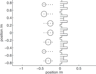
As a starting point for investigation, a regularly spaced line of cylinders is positioned symmetrically in front of a periodic Schroeder diffuser. The Schroeder diffuser is com-posed of 5 repetitions of a quadratic residue diffuser共QRD兲 of design frequency 500 Hz; the well depths of each QRD are determined by a quadratic residue sequence of length 7, well widths are 5 cm and fins are included between wells, as shown in Fig.1. Receivers are regularly spaced on a semi-circle of radius 10m, centered on the face of the Schroeder diffuser. A planar source wave is incident normal to the Schroeder diffuser.
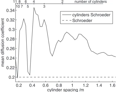
Cylinders are of radius 5 cm, positioned 10 cm in front of the face of the Schroeder diffuser. Spacing between cyl-inders is varied from 0.15 m to 1.65 m, with the number of cylinders present for each spacing determined by the total width of the Schroeder diffuser of 1.75 m; two examples of different spacing are shown in Fig.1. To assess performance, the average of the diffusion coefficient in the frequency range 340–3400 Hz is calculated; although diffusion can vary greatly with frequency, an average is taken to help
sim-plify data and identify trends. Results are shown in Fig. 2, with the number of cylinders present for different spacing shown at the top of the graph.
Significant improvements to the Schroeder diffuser are evident in Fig. 2. Except for cylinder spacing close to the Schroeder period width and half width共0.35 m and 0.175 m respectively兲, cylinders have a consistent positive effect on diffusion, increasing the mean diffusion coefficient in the frequency range 340–3400 Hz by up to around 70%. Even the presence of just two cylinders is able to offer notable diffusive benefits, which could prove particularly useful where space is limited. It is worth noting that if the cylinders are positioned further from the Schroeder diffuser, perfor-mance remains very similar, but closer positioning is likely to be more practically desirable. For simplicity, only cylin-ders are considered in this investigation, but the marked de-pendence of diffusion on lateral spacing suggests that objects of difference cross-sections may also be able to provide dif-fusive benefits provided they are appropriately spaced.
In order to further understand the results of Fig. 2, two differently spaced cylinder arrays are considered in greater detail. These are selected to represent the worst and best performance of cylinders according to Fig.2; one is a line of 5 cylinders spaced according to the Schroeder period width, and the other is a line of 4 cylinders with 43 cm center-to-center spacing, as shown in Fig.1with dotted and solid lines respectively.
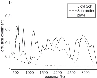
Results for the diffusion coefficient across the frequency range 340–3400 Hz for each arrangement, as well as for the Schroeder diffuser alone, are shown in Fig.3; the result with-out cylinders for a flat plate of the same total width is also displayed to provide a reference as a non-diffusing surface.
As suggested by Fig. 2, the 5 cylinder array has little effect on the quality of diffusion — the commensurable spac-ing of cylinders means that periodicity in the Schroeder dif-fuser is unaffected. In contrast, the 4 cylinder array has a consistent positive effect, which is attributable to the non-simple relation between the period width of the Schroeder
−1 −0.5 0 0.5 1
−0.8 −0.6 −0.4 −0.2 0 0.2 0.4 0.6 0.8
position /m
position
[image:3.612.333.538.33.196.2]/m
FIG. 1. Schroeder diffuser composed of 5 repetitions of a length 7 QRD, design frequency 500 Hz, with 5 cylinders共dotted circles兲and 4 cylinders
共solid circles兲, cylinder radius 5 cm. Cylinder centers are 10 cm from the Schroeder face.
0.2 0.4 0.6 0.8 1 1.2 1.4 1.6
0.2 0.22 0.24 0.26 0.28 0.3 0.32 0.34
cylinder spacing /m
mean
diffusion
coefficient
cylinders Schroeder Schroeder
number of cylinders 11
10 8 7
6 5
4 3
[image:3.612.71.275.33.191.2]2
FIG. 2. Mean of the diffusion coefficient in the frequency range 340–3400 Hz versus spacing between cylinders. The Schroeder period width is 35 cm. The number of cylinders present for different spacing is shown at the top of the graph; this is limited by the total width of the Schroeder diffuser of 1.75 m.
diffuser and the center-to-center spacing of cylinders. Im-provements due to the 4 cylinder array appear fairly uniform across the frequency range.
At around 3500 Hz, where the Schroeder diffuser be-haves as a flat plate due to all wells re-radiating in phase,1 little benefit is provided by the cylinders, since performance here is unaffected by periodicity, hence there is little scope for improvement by the regular line of cylinders; however, multiple layers of cylinders, or staggering cylinders relative to the Schroeder diffuser, might be able to address this 共as considered later with regard to optimization兲. Behavior be-low around 1000 Hz, where the Schroeder device provides little diffusion, is improved by the 4 cylinder array, and will be considered further below.
It is worth noting that the lateral spacing of cylinders is key to the diffusive effect: if the 5 cylinder array were shifted such that it were no longer centered on the Schroeder dif-fuser, or the lateral spacing of the 4 cylinder array were made equal to the Schroeder period width, similar results would be obtained as for the 5 cylinder arrangement in Fig.3共results not shown兲.
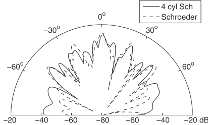
As another measure of performance, a polar plot of scat-tering is shown in Fig.4. Sound pressure levels of scattering are displayed for a 2500 Hz source wave at normal incidence to the 4 cylinder arrangement in Fig. 1, as well as for the Schroeder diffuser alone. The reduction of grating lobes by the cylinder array is evident in the polar plot, particularly
around⫺60°, 15°, 40° and 80°. Scattering amplitude at ob-lique angles is also increased. From Fig.3it appears that this improvement is fairly representative of the benefits provided by the 4 cylinder array.
Although diffusers are frequently positioned normal to the incident sound, this is not always the case: devices are sometimes positioned on side walls or at an angle, while a variety of source locations might occur, and reflections from different directions may be significant; a good diffuser should therefore perform well over a range of incident angles.
To assess angular dependence, the 4 cylinder arrange-ment shown in Fig. 1 is again used, and the diffusion coef-ficient between 340–3400 Hz is averaged for different angles of incidence, as shown in Fig. 5. The positive effect of cyl-inders appears consistent across all angles, displaying a very similar angular dependence to the Schroeder diffuser alone. This is because the main effect of cylinders is to counteract periodicity in the Schroeder diffuser, which is unaffected by incident angle.
Low frequency diffusion is a key aspect of diffuser de-sign, as space constraints often limit performance. The 4 cyl-inder array in Fig.1 is used as a basis for further investiga-tion of the effect of cylinders on low frequency diffusion from the Schroeder diffuser. Of interest is the effect of cyl-inder size and the distance between the Schroeder diffuser and cylinders. The quality of diffusion is assessed by aver-aging the diffusion coefficient in the range 340–1040 Hz
共wavelengths 1–0.33 m兲, where the Schroeder diffuser alone provides little diffusion共as evident in Fig.3兲. The results of varying cylinder radius and separation between the Schroeder diffuser and cylinders are shown in Fig.6.
Low frequency diffusion improves steadily with increas-ing cylinder radius up to around 10 cm, due to larger cylin-ders providing greater scattering amplitude at low frequency, hence having a greater effect on diffusion. To provide low frequency improvements to the Schroeder diffuser, cylinders must therefore be sufficiently large: to significantly scatter sound12 at wavelength , cylinder radius aⲏ/2. The re-sult tends to level off for larger radii in Fig. 6, which is due to the diffusion coefficient being averaged over a range of frequencies — if a lower frequency upper limit were used,
500 1000 1500 2000 2500 3000
0 0.2 0.4 0.6 0.8 1
frequency /Hz
diffusion
coefficient
[image:4.612.71.275.32.196.2]5 cyl Sch 4 cyl Sch Schroeder plate
FIG. 3. Diffusion coefficients for the arrays shown in Fig.1, including results for the Schroeder diffuser alone and a flat plate of the same width.
−20 −40 −60 −80 −60 −40 −20 dB
60o
30o
0o
−30o
−60o
[image:4.612.332.538.37.191.2]4 cyl Sch Schroeder
FIG. 4. Polar plot of scattering at 2500 Hz for 4 cylinders with Schroeder diffuser共solid line兲as shown in Fig.1, and Schroeder alone共dashed line兲.
−90 −60 −30 0 30 60 90
0.2 0.25 0.3 0.35 0.4 0.45 0.5
incident angle /degrees
mean
di
ff
usion
coe
ff
icient
4 cyl Sch Schroeder
[image:4.612.68.274.590.714.2]the leveling off would shift to a larger cylinder radius共results not shown兲. A small fluctuation in low frequency diffusion is observed for the largest cylinder radius with the smallest separation between cylinders and the Schroeder wells, which is presumably due to the proximity of the cylinder surface to the Schroeder well resulting in less predictable scattering be-havior.
Results suggest that low frequency diffusion does not increase with the separation between the Schroeder diffuser and cylinders; in fact, moving cylinders further away from the Schroeder diffuser seems to reduce low frequency diffu-sion due to the weaker coupling between cylinders and wells resulting in a smaller diffusive effect. This implies that im-provements to low frequency diffusion by the cylinders is not due to multiple scattering paths effectively increasing the depths of the Schroeder wells, but simply through breaking up periodicity: at low frequency, diffusion from the Schroeder device in this instance is limited by periodicity rather than depth,1and the reduction of the effects of period-icity by the cylinders appears to be the reason for low fre-quency improvements.
III. REGULAR ARRAYS WITH OTHER SCHROEDER DIFFUSERS
Only a single type of Schroeder diffuser has been con-sidered so far. Of interest is the effect of cylinders on other Schroeder devices, including one designed to perform over a narrower bandwidth, which due to its smaller size might be implemented where space is limited. To investigate this, a Schroeder diffuser is composed of 5 repetitions of a length 7 QRD, similar to previously, but with design frequency 1500 Hz and well widths 3 cm. The cylinder array is based on the 4 cylinders in Fig.1but with 30 cm lateral spacing due to the smaller total width of the Schroeder diffuser. Diffusion coef-ficient results are shown in Fig. 7. Improvements to the Schroeder device by the cylinders are very similar to previ-ously, including a reasonable enhancement to diffusion be-low the design frequency.
The main contribution of cylinders appears to be in tack-ling problems associated with periodicity in the Schroeder diffuser. This has been addressed in the past by modulating different Schroeder base shapes to form larger devices,13and it is of interest whether cylinders are able to provide further improvements to such a design. As a basis for investigation, a length 7 QRD 共A兲 of design frequency 500 Hz is modu-lated with a length 5 QRD共B兲of the same depth to form a sequence ABBABA.1The same 5 cylinder array as in Fig.1 is centered 25 cm in front of the modulated Schroeder de-vice, and diffusion coefficients for the arrangement are plot-ted in Fig.8.
The presence of cylinders again improves performance, albeit less dramatically; the average diffusion coefficient is 0.36, compared with 0.25 for the Schroeder diffuser alone. Although the spacing of the 5 cylinders was previously not beneficial to diffusion共due to being commensurable with the Schroeder period兲, the changes to the Schroeder diffuser mean this is no longer the case, despite the length 7 QRDs in the modulation having the same width as used previously. However, performance fluctuates quite markedly across the frequency range, which appears to be due to the modulation
0.05 0.1 0.15
0.2 0.25 0.3 0.35 0.4
cylinder radius /m
mean
diffusion
coefficient
[image:5.612.333.539.33.195.2]cyl Sch 0.2m cyl Sch 0.5m cyl Sch 1m Schroeder
FIG. 6. Mean of the diffusion coefficient in the frequency range 340–1040 Hz共wavelengths 1–0.33 m兲versus cylinder radius, based on the 4 cylinder arrangement in Fig.1. Results are shown for 3 different distances between the cylinders and Schroeder diffuser共0.2 m, 0.5 m and 1 m兲, as well as for the Schroeder diffuser alone.
500 1000 1500 2000 2500 3000
0 0.2 0.4 0.6 0.8 1
frequency /Hz
diffusion
coefficient
[image:5.612.70.274.36.188.2]4 cyl Sch Schroeder plate
FIG. 7. Diffusion coefficients for array similar to the 4 cylinder arrangement in Fig.1, but with Schroeder well widths 3cm and design frequency 1500 Hz, and lateral cylinder spacing 30 cm.
500 1000 1500 2000 2500 3000
0 0.2 0.4 0.6 0.8 1
frequency /Hz
diffusion
coefficient
5 cyl Sch Schroeder plate
FIG. 8. Diffusion coefficients for array similar to the 5 cylinder arrangement in Fig.1, but with the Schroeder diffuser composed of a length 7共a兲and length 5共b兲QRD modulated to form a sequence ABBABA. The 5 cylinder array is spaced 25 cm from Schroeder face.
[image:5.612.333.538.527.692.2]of the Schroeder diffuser affecting the frequencies at which the regularly spaced cylinders are able to improve diffusion. This may correspond with the fact that spacing the cylinders at 25 cm rather than 10 cm from the Schroeder diffuser pro-vides better performance, which did not appear to be the case for periodic devices.
IV. OPTIMIZATION
The introduction of irregular cylinder radii and positions should benefit diffusion by increasing roughness over a range of length scales, thus providing more random scattering from cylinders over a variety of frequencies. While it is not pos-sible to evaluate systematically all combinations of effects, an optimization procedure is able to search in an automated manner for favorable arrangements from a number of parameters.14In order to simplify investigation, cylinders are restricted to a grid with only a discrete set of possible radii; not only does this make the optimization procedure more straightforward by reducing the size of the search space, it also means results would be more practically viable to con-struct.
A genetic algorithm is the most appropriate method of optimization due to the discrete nature of arrangements, and a standard procedure is implemented.1 The performance of each array is assessed in terms of a single metric, which is selected as the mean of the diffusion coefficient for normal incidence over the range 340–3400 Hz minus the standard deviation, thus reflecting both overall effectiveness and uni-formity of diffusion. There will realistically be several simi-larly good results, and a global maximum is very unlikely to be found, so in practice the algorithm is only expected to obtain reasonable diffusion results. This is especially note-worthy because by imposing particular grid positions and radii, it means that even if a global maximum were found for those particular constraints, the maximum would only be for a fairly arbitrary configuration. For convenience and applica-bility to existing diffusers, Schroeder well depths are not optimized by the genetic algorithm.
An array of grid points is positioned symmetrically in front of 5 repetitions of a length 7 QRD, as shown in Fig.9. Grid positions may be either empty or occupied by a cylinder
of radius 2.5, 5 or 7.5 cm. The grid is composed of 7 rows
共each running perpendicular to the Schroeder face兲 and 5 columns. Spacing between rows is 25 cm, which is incom-mensurable with the Schroeder period width; based on Fig. 2, this spacing should provide good diffusion, and offers more scope for optimization than the 43cm spacing consid-ered previously, which would only allow space for 4 rows. Each row may contain at most 1 cylinder, meaning no cyl-inder is obscured. Columns are separated by 5.62 cm, and lie between 20 cm and 42.48 cm from the Schroeder face. The setup is intended to provide a single-layer cylinder array which includes variation of cylinder radii and positions.
The genetic algorithm is performed using a multiple scattering approximation,4 and results are validated using BEM. A successful array is shown in Fig.9; worth noting is that all rows have cylinders, and only the two largest cylin-der radii are present. Corresponding diffusion coefficient re-sults obtained using BEM are shown in Fig. 10. The diffu-sion coefficient for the whole array is compared against that for the Schroeder diffuser alone and a flat plate of the same width.
The optimized sequence of cylinders provides consider-able improvements to diffusion across the frequency range, with a mean diffusion coefficient of 0.46; this provides a 130% increase over the result for the Schroeder diffuser alone, and an increase of around 35% over the best regular array spacing in Fig.2. Although some larger cylinders are present in the optimized array than in Fig.2, this alone does not account for the increase in diffusion; rather it is the com-bination of different positions and radii. Perhaps most sig-nificant is the removal of the Schroeder plate frequency at around 3500Hz; the irregularity of the array means the cyl-inders are able to address issues other than just those associ-ated with periodicity in the Schroeder diffuser. Non-optimized arrays can provide diffusive benefits approaching those of the optimized array; results are not shown for sim-plicity, but a good example is obtained by staggering cylin-ders on the grid points shown in Fig. 9 according to a qua-dratic residue sequence.
To ensure that results are not ‘over-fitted’,1where arrays only perform well for the conditions used to rank them in the genetic algorithm rather than being good diffusers in a
−1 −0.5 0 0.5
−0.8 −0.6 −0.4 −0.2 0 0.2 0.4 0.6 0.8
position /m
position
[image:6.612.71.274.33.190.2]/m
FIG. 9. Cylinder array generated by genetic algorithm. Grid points for pos-sible positions are shown by dots. Cylinders are of radius 5 cm and 7.5 cm.
500 1000 1500 2000 2500 3000
0 0.2 0.4 0.6 0.8 1
frequency /Hz
di
ff
usion
coe
ff
icient
[image:6.612.333.538.33.195.2]whole array Schroeder plate
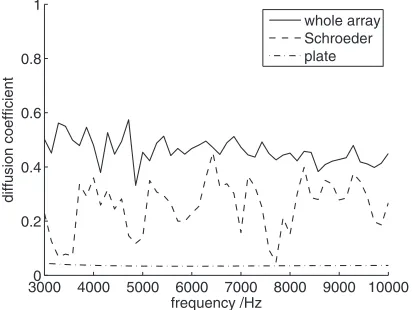
broader context, the array is tested with different angles of incidence and frequencies, suggesting that the result is ro-bust; an example is shown in Fig. 11, which demonstrates stronger and more uniform diffusion across frequencies with the optimized arrangement than for the Schroeder diffuser alone.
V. CONCLUSION
Positive results have been obtained for the diffusive ef-fects of cylinders positioned in front of a Schroeder diffuser, which could be straightforwardly applied or retrofitted to ex-isting devices. The effects of cylinders appear uniform across different angles of incidence. Cylinders are able to provide improvements to diffusion at low frequencies, provided cyl-inder radii are sufficiently large to cause significant scatter-ing. Further to improving diffusion, cylinders may also pro-vide aesthetic advantages.
Clear diffusive benefits are demonstrated with a very simple line of cylinders in front of a periodic Schroeder de-vice, provided cylinder spacing is incommensurable with the Schroeder period width. Cylinders also offer benefits to nar-rowband and, to a lesser extent, modulated Schroeder de-vices, with increases to the diffusion coefficient in the fre-quency range 340–3400 Hz typically at least around 50%.
Further improvements are obtained by an optimization method, including the removal of Schroeder plate frequen-cies, which demonstrates the benefits of staggering cylinders of different sizes, although the simplicity of an incommen-surable row of regularly spaced cylinders may be most prom-ising in terms of practical implementation.
ACKNOWLEDGMENTS
This work was funded by the UK Engineering and Physical Sciences Research Council 共EPSRC兲, under Grant No. EP/D031621.
1T. J. Cox and P. D’Antonio,Acoustic Absorbers and Diffusers, 2nd ed.
共Spon, London, 2009兲, pp. 289–330.
2H. Kuttruff,Room Acoustics, 4th ed.共Spon, London, 2000兲, pp. 55–58. 3M. R. Schroeder, “Binaural dissimilarity and optimum ceilings for concert
halls: More lateral sound diffusion,” J. Acoust. Soc. Am.65, 958–963
共1979兲.
4M. Pogson, D. M. Whittaker, G. A. Gehring, R. J. Hughes, J. A. S. Angus,
and T. J. Cox, “Multiple scattering between cylinders and a Schroeder diffuser,” Acta. Acust. Acust.96, 292–299共2010兲.
5T. J. Cox, R. J. Hughes, J. A. S. Angus, D. M. Whittaker, M. Pogson, and
G. A. Gehring, “Volumetric diffusers inspired by percolation fractals,” in Proceedings of the Institute of Acoustics共2008兲, Vol.30.
6O. Umnova, K. Attenborough, and C. M. Linton, “Effect of porous
cov-ering on sound attenuation by periodic arrays of cylinders,” J. Acoust. Soc. Am.119, 278–284共2006兲.
7J. V. Sánchez-Pérez, D. Caballero, R. Martinez-Sala, C. Rubio, J.
Sanchez-Dehesa, F. Meseguer, J. Llinarez, and F. Galvez, “Sound attenuation by a two-dimensional array of rigid cylinders,” Phys. Rev. Lett.80, 5325–5328
共1998兲.
8P. Boulanger, K. Attenborough, Q. Qin, and C. M. Linton, “Reflection of
sound from random distributions of semi-cylinders on a hard plane: Mod-els and data,” J. Phys. D: Appl. Phys.38, 3480–3490共2005兲.
9P. D’Antonio and T. J. Cox, “Diffusor application in rooms,” Appl.
Acoust.60, 113–142共2000兲.
10T. J. Cox, “Predicting the scattering from reflectors and diffusers using
two-dimensional boundary element methods,” J. Acoust. Soc. Am. 96, 874–878共1994兲.
11A. Håkansson, F. Cervera, and J. Sánchez-Dehesa, “Sound focusing by flat
acoustic lenses without negative refraction,” Appl. Phys. Lett.86, 054102
共2005兲.
12P. M. Morse and K. U. Ingard,Theoretical Acoustics共Princeton University Press, Princeton, NJ, 1986兲, pp. 400–405.
13J. A. S. Angus, “Using grating modulation to achieve wideband large area
diffusers,” Appl. Acoust.60, 143–165共2000兲.
14J. Nocedal and S. J. Wright,Numerical Optimization共Springer, New York, 2006兲, pp. 1–3.
30000 4000 5000 6000 7000 8000 9000 10000 0.2
0.4 0.6 0.8 1
frequency /Hz
di
ff
usion
coe
ff
icient
[image:7.612.70.278.33.188.2]whole array Schroeder plate
FIG. 11. Diffusion coefficients for result from genetic algorithm in Fig.9, with source wave incident at 45° across frequency range 3–10 kHz.