International Journal of Emerging Technology and Advanced Engineering
Website: www.ijetae.com (ISSN 2250-2459,ISO 9001:2008 Certified Journal, Volume 3, Issue 10, October 2013)
588
Automated Wheel Assembly System Using PLC
J. Dilipsingh
1, S. Jeyanthi
2, R. S. Jagadeesh
31ME-Mechatronics, second year, 2Associate professor, 3BE final year, Jeppiaar Engg college, Chennai.
Abstract- Actual system is difficult to handle, set up to evaluate the performance of a wheel loading system, the simulation package should be available to estimate the performance of the system with a chosen robot The automated wheel assembling system reduces human effort time, energy. The continous work is done with the robot accurately. Here the camera is replaced by the IR sensor which the price is drastically reduced and equals the same work
I. INTRODUCTION
In automotive manufacturing, wheel loading is the process to mount the wheels onto a car when the production line is moving at random speed. Currently this process is done by the operators w/o assisted devices as shown in Figure.
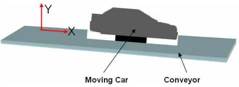
There are typically 6 operators per shift in each production line and two shifts a day for wheel loading. Therefore, t he cost for wheel loading is about 1.5 million dollars each year for an assembly line based on the current cost of an operator(about $130K per year in the United States. The demand to automate the wheel loading process is getting higher and higher, especially when the automotive manufacturing is facing difficult time. There are many challenges to automate the wheel loading process. When the car is moving on the production line, it could move along both the X and Y directions at random speed as shown in Figure 2. Therefore, the automated wheel loading system should be able to track the random motion of the car accurately since the assembly tolerance of wheel loading is quite small. Also wheel loading is close to the final step of the whole car assembly and the car is almost ready to go. Thus, a small damage to the car could cause a big loss. Therefore, the developed automation system must be compliant to the motion of the car once the wheel contacts the car.
[image:1.612.325.563.197.376.2]Industrial robots have increased in both number and complexity over the years for assembly tasks because o flexibility and the increasing requirements of product quality and quantity. However, assembly robots are still a small portion of total robot sales each year.
Figure 1 The current manual wheel loading process. Typically there are 6 operators per shift and two shifts per day.
Figure 2 The car is moving randomly along both the X and Y directions on the conveyor.
One of the main reasons is that it is difficult for conventional industrial robots to adjust to any sort of change of the assembly processes. Therefore, more intelligent industrial robotic systems have to be developed in order to perform complex assembly tasks like wheel loading.
[image:1.612.325.564.407.494.2]International Journal of Emerging Technology and Advanced Engineering
Website: www.ijetae.com (ISSN 2250-2459,ISO 9001:2008 Certified Journal, Volume 3, Issue 10, October 2013)
589 However, only one direction motion (X axis in Figure 2) is tracked and the wheel hub has to be well aligned in the direction of the motion of the conveyor. But the wheel hub cannot be exactly aligned at the same direction for all cars on the production line. Yoon [2] used stereo vision to identify the wheel hub position and orientation while the production line is moving. However, the pose estimation errors are more than 3mm that is more than the wheel loading tolerance. Therefore the developed system is not ready for use in the actual wheel loading process. Moreover ,these systems use only visual servoing to track the motion of the car to perform the assembly tasks. In wheel loading, the malfunction of the visual servoing could damage the car body, which is very costly.
To make the robotic system compliant with the contact environment, force control can be used. Therefore, to enable wheel loading, visual servoing and force control have to be integrated to control the motion of the robotic system .Beaten et al. developed a hybrid vision and force control strategy to follow the contour of planar surface. Xiaoet al, Chang et a and Olsson et al. presented methods to follow a curve on a surface while maintaining a certain contact force. Although these methods can deal with the feature following based on hybrid control strategy, the applications in the moving object tracking while performing certain tasks are not discussed. Nelson et al. discussed different methods based on vision and force control, such as hybrid control, traded control and shared control methods. Interesting experimental results are presented regarding the performance of these methods. However, the force control is only used to maintain a certain contact force. Although combination of vision and force control strategy has been widely studied, no practical implementation in wheel loading has been done based on the synergistic combination of vision, force and position as the feedback information.
Because the stereo vision system requires high quality camera, accurate calibrations and high computation power, the existing systems are costly, error prone and not robust enough for daily use at the workshop. Also the complicated computation for determining the position/orientation of an object makes the system difficult to be implemented in real time applications. Furthermore, the visual servoing alone could cause damages to the final products if the vision system is malfunctioned. Hence a simple IR system combined with force control is a better solution for industrial applications.
To perform an assembly using a IR sensors system, the errors along the X- and Y-axes of the moving part can be compensated by signal servoing, however, the Z axis errors are difficult to compensate using IR.
Thus, force control can be applied to control the motion of a robotic system to perform an assembly task along the Z axis.here.it discusses an assembly technology for wheel loading while the car is moving based on signal servoing and force control. The wheel loading system had been set up and experiments were performed successfully. The experimental results demonstrate that the developed technology can also be used for assembly while the part on the assembly line is moving randomly.
A. Wheel Loading Process
The wheel loading process is to mount the wheel onto the wheel hub on the car as shown in Figure 3. The holes on the wheel hub mount the wheel onto the wheel hub to match the studs on the wheel hub in order to
Figure 3
II. MOUNT THE WHEEL ONTO THE WHEEL HUB PAGE
LAYOUT
International Journal of Emerging Technology and Advanced Engineering
Website: www.ijetae.com (ISSN 2250-2459,ISO 9001:2008 Certified Journal, Volume 3, Issue 10, October 2013)
590 The robot then starts to track the motion of the car while the wheel mounting is performed. If the process is successful, the gripper is open and the wheel is mounted on the wheel hub. The robot tool is then retracted. If the process fails, the robot tool with the wheel is retracted. Manual wheel loading has to be performed to fix the problem.
The general design is made in different software to find the accuracy of the design and the simple design is done in wild fire pro e 5. This simple model gives the general expression of the robotic assembly system.
Simple Proe model of a system
1. The IR sensor identifies the position/orientation of a wheel and picks it up
2. The robot moves to the starting position (taught manually).
[image:3.612.324.565.442.561.2]The IR sensor will give the info to the conveyor triggers the first trigger. After image processing, the orientation pattern of the bolts on the hub is identified. The robot Axis 7 will rotate to match the holes on the wheel to the studs on the wheel hub.
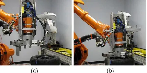
Figure 6 The robot picks up a randomly located wheel. (a) The wheel is randomly located on a feeding table. (b) The vision system automatically identifies the location of the wheel to control the robot
to pick up the wheel.
International Journal of Emerging Technology and Advanced Engineering
Website: www.ijetae.com (ISSN 2250-2459,ISO 9001:2008 Certified Journal, Volume 3, Issue 10, October 2013)
591 4.Once the contact force along Z-axis reaches the set
value and the tool position along the assembly direction reaches the set value, the assembly completes and the force control along the negative Z-axis will retract the robot.
5.The force control along all directions will keep the system safe under abnormal conditions. For example, when the vision system sends wrong signals, the force control will balance the wrong signals and will not cause damage to the system and the product.
B. Control System Structure
The developed wheel loading system can track the moving car body while mounting the wheel onto the wheel hub based on the vision, force and position sensor fusion.
The motion of the conveyor is typically random with the velocity change along both the X and Y directions. Hence the robot has to track the motion of the moving part along both the X and Y directions in order to perform the assembly processes. This is different from the typical conveyor tracking process which only the motion along the X direction is controlled.
Since the system involves the vision system, force control system and the robot control system, the control system structure is discussed first.
An easy way to complete y with the conference paper formatting requirements is to use this document as a template and simply type your text into it.
Since the system involves the vision system, force control system and the robot control system, the control system structure is discussed first.
PLC controller.
The control system hardware setup is shown in Figure 8. The IR sensor system processes the signals and sends the position signals to the robot controller (IRC5, an ABB controller) to control the motion of the robot to follow the motion of the object. The force sensor measures the contact force to adjust the motion of the robot. The force control also makes the robot compliant to the environment to avoid the damage to the contact object.
In the IR system, a pre-defined feature on the moving part is identified by a saved signals. The position error of the feature compared with the desired feature in the frame is computed to control the motion of the robot as shown in, the robot can only track the motion of the moving part along the X and Y directions. To perform an assembly, the robot has to be controlled to approach the moving part. Therefore, force control along the Z axis is applied to control the motion of the robot to perform the wheel loading process. Since the infrared servoing alone could cause damages to the final products if the IR system is malfunctioned, the force control along both the X and Y axes are also enabled to make the robotic system compliant to the contact environment.
International Journal of Emerging Technology and Advanced Engineering
Website: www.ijetae.com (ISSN 2250-2459,ISO 9001:2008 Certified Journal, Volume 3, Issue 10, October 2013)
592 There are several coordinate frames involved in the system: the conveyor frame (work object frame), the feature frame, the camera frame, the tool frame (gripper), the force sensor frame, the robot base frame and the world frame. Most of the frames are common except the feature frame. The feature frame is defined on the center of the feature and is parallel to the work object frame
C. Intelligent Control System
Since the wheel loading process needs human knowledge, an intelligent robotic system is developed to perform the complicated assembly process. The intelligent robotic system uses the following rules.
If the feature is detected, then the robot starts to track the moving car. The feature is defined by the user, either a real feature on the car or an added feature. The motion controller is enabled to control the assembly process after the feature is identified .
If the contact force between the robot tool and the moving car reaches a set value and the tool position reaches a set value along the assembly direction (Z axis ) then the assembly process is completed and the robot tool is retracted. Since the object is moving randomly, the location of the completion point is different at each assembly.
If the contact force in one of the tool directions is larger than a maximum set value, then the robot tool is retracted to avoid damage to either the car body or the robotics system.
When the contact force is too big, there may be a jam between the robot and the moving object. Since both the robotic system and the moving car on the production line are quite stiff, they have to be separate rapidly to avoid damage. Therefore, quick retreat is needed.
If the robot tool approaches the assembly contact point along the assembly direction, the control coefficients should be switched. The contact point is different at each assembly .Before the robot tool reaches the point, the visual servoing control dominates the control loop since the tracking accuracy is important. Once the robot tool contacts the moving object, the robot should be compliant to the environment to avoid damage of the robotic system and the moving car. Therefore, the force control should dominate the control loop.
These rules are important to make the assembly process successful. Since the car is moving randomly, the assembly completion point and the contact point etc. cannot be preprogrammed.
Therefore, the developed intelligent system can deal with the change of the working environment.
The motion of the robot is controlled by the robot controller based on the vision and force sensor inputs. The control system structure
III. PAGE STYLE
After the feature error is identified, it is input to the visual servoing controller to correct the feature error. The force sensor measures the contact force and torque. The desired force and torque are controlled to be zero except the Z axis that is controlled to move the robot towards the moving car.
The force and torque errors are sent to the force controller to control the contact force. This is a tradeoff between the visual servoing and force control that is achieved by controlling the controller gains. These computed velocity errors are input to the robot controller to regulate the robot velocity to achieve the desired performance.
IV. EXPERIMENTAL IMPLEMENTATION AND RESULTS
To validate the developed method, experiments were implemented to perform the wheel loading process while the car is moving on an assembly line. There are several calibrations involved in the wheel loading process. First, the holes on the wheel and the studs on the wheel hub have to be matched. This is done by teaching the tool orientation. While moving the robot tool around the feature, the transformation between the tool frame, the feature frame and the camera frame is then computed. The transformation between the wheel and camera frame is calibrated by moving the camera to several different positions while the images are captured.
International Journal of Emerging Technology and Advanced Engineering
Website: www.ijetae.com (ISSN 2250-2459,ISO 9001:2008 Certified Journal, Volume 3, Issue 10, October 2013)
[image:6.612.49.285.198.378.2]593 Thus the tolerance of the assembly is about 2mm from the center of the hole. Since the wheel hub is moving randomly with the car on the conveyor, the tracking error must be less than 2mm to install the wheel onto the wheel hub successfully.
[image:6.612.333.545.263.613.2]Figure 11 The robot tracks the motion of the wheel hub while the force control enables the tool approaches the wheel hub.
Figure 12 The wheel is successfully installed on the wheel hub. The assembly process is completed.
Figure 11 and Figure 12 show the successful wheel loading process. The robot tool grips the wheel and tracks the motion of the wheel hub. The wheel is then installed on the wheel hub based on force control and visual servoing.
The force control is enabled along all direction to make the system flexible to the environment. The system compliance was observed after the wheel is mounted.
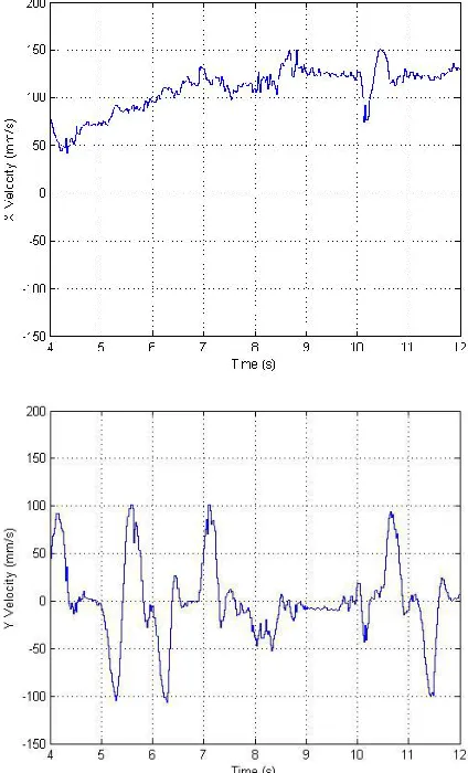
The random motion of the robot tool is recorded and shown in Figure 13. 1Hz filter is used to smooth the signals. The tool velocity is about 120mm/s along the X direction that is the typical conveyor velocity in the trim-and-final assembly. The maximum tool velocity is about 100mm/s and the frequency is about 2Hz along the Y axis. These values are much worse than the actual trim-and-final assembly conveyor system (communicating with experts in the trim and-final assembly area in automotive production line).
Figure 13 The recorded tool velocity along the X and Y directions. 1Hz filter is used to smooth the signals.
[image:6.612.50.287.403.588.2]International Journal of Emerging Technology and Advanced Engineering
Website: www.ijetae.com (ISSN 2250-2459,ISO 9001:2008 Certified Journal, Volume 3, Issue 10, October 2013)
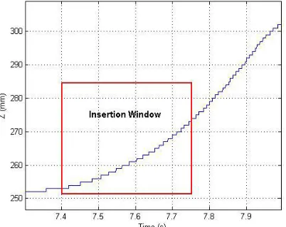
[image:7.612.65.266.148.308.2]594 At the beginning (from 4.8s to 7s), the wheel is controlled to approach the wheel hub. The robot then waits there until the tracking error is less than a set value (0.75mm in the experiments to ensure the successful assembly). After that, the wheel is controlled to move fast to insert the wheel onto the wheel hub (from 7.4s to 7.75s) and then settled down on the wheel hub plate (from 7.75s to 8.5s). After the wheel is mounted, the robot tool is retracted to disengage the robot tool and the car. The critical part of the wheel loading process is the insertion window. In the insertion window, the tracking errors along both the X and Y axes must be less than the assembly tolerance that is2mm. The insertion distance is set to be 20mm since the car location along the Z axis may not be consistent for all cars .The wheel and the wheel hub should not contact before insertion. Otherwise the insertion may fail because of the contact. The insertion time is about 350ms for the current system.
Figure 15 Recorded position errors during the wheel mounting process.
Therefore, the tracking errors must be less than 2mm during the insertion time. Hence the tracking errors should be analyzed.
V. CONCLUSIONS
Since most current industrial robots have to be preprogram d with very little adaptation in their task execution, they are difficult to satisfy the increasing complex manufacturing requirements, such as wheel loading. In this paper, an automated wheel loading system is developed based on the synergic combination of visual servoing and force control strategy. Visual servoing is used to track the 2D motion of the car on the conveyor. Experiments were performed successfully and the results demonstrated that the developed technology can be used for wheel loading. Since huge amount of time and resource can be saved using the developed robotic system, this innovative technology will have great impact in the automotive industry, especially when automotive manufacturing is facing difficulties
REFERENCES
[1] C. Cho, S. Kang, M. Kim, and J. Song, “Macro-Micro Manipulation with Visual Tracking and its Application to Wheel Assembly”, ,The International Journal of Control, Automation, and Systems, vol. 3, no. 3, pp. 461-468, September 2005.
International Journal of Emerging Technology and Advanced Engineering
Website: www.ijetae.com (ISSN 2250-2459,ISO 9001:2008 Certified Journal, Volume 3, Issue 10, October 2013)
595
[3] J. Baeten and J. D. Schutter, “Hybrid vision/force control at corners in planar robotic-contour following,” IEEE/ASME Transactions on Mechatronics, vol. 7, no. 2, pp. 143 – 151, June 2002.
[4] J. Baeten, H. Bruyninckx, and J. D. Schutter, “Tool/camera configurations for eye-in-hand hybrid vision/force control,” in IEEE International Conference on Robotics and Automation, Washington, DC, pp. 1704-1709, May 2002.
[5] D. Xiao, B. K. Ghosh, N. Xi, and T. J. Tarn, “Sensor-based hybrid position/force control of a robot manipulator in an uncelebrated environment,” IEEE Transactions On Control Systems Technology, vol. 8, no. 4, pp. 635–645, July 2000.
[6] W. Chang and C. Wu, “Integrated vision and force control of a 3-DOF planar surface,” in IEEE Int. Conference on Control Applications, Glasgow, Scotland, U.K., September 2002, pp. 748– 753.