Abstract— An intentional islanding operation or a planned
islanding operation is feasible with the advance technologies introduced by a smart distribution system. This paper highlights a well planned islanding operation facilitating with an intelligent control strategy for a Distributed Generation (DG) to operate islanded and cater the issue of different islanding area. For radial system network, the DG could be serving several islanding areas as a result of different fault locations. For each islanding area, the governor’s controller is properly designed such that the DG exhibits a good dynamic response once a part of the network is islanded. A means to automatic synchronized the islanded network with the grid for reconnection process is also considered in the controller. The controller has been modeled considering the existing Malaysia’ distribution network of mini hydro power plant connected in parallel to the grid. The transient stability response of the generator is observed particularly on the frequency not to exceed the maximum allowable protection setting. The results proved that the DGs are feasible to operate in the islanded system despites slow dynamic response of hydro turbine to reach steady state. In addition, the slow transient response of hydro governor turbine has given a challenge in designing the controller algorithm.
Index Terms—Islanded Operation, Smart Grid, Hydro Power
Station, Governor’s Controller
I. INTRODUCTION
hen considering a high penetration of Distributed Generation (DG), the decision to disconnect DG when islanding occurs is not appropriate. Ideally, the utility shall fully utilize the DG to supply the load in the islanded system. However, without a proper coordination and control of an islanding operation, the idea to implement islanding poses risks and hazards to the island and the grid. This requires a smart distribution system so called ‘Smart Grid’ comprising monitoring, control, analysis and communications capabilities to achieve a seamless and synchronized islanded operation. Advanced technologies together with fast and
This work is supported by the University of Malaya (e-science fund:-106-01-03-SF0562) and the University of Technology MARA, Malaysia.
H. Mohamad is with the Faculty of Electrical Engineering, University of Technology MARA, Malaysia.( e-mail:[email protected])
A.H.Abu Bakar is with the Centre of Research UMPEDAC, Department of Electrical Engineering, Faculty of Engineering, University of Malaya,Kuala Lumpur, Malaysia (e-mail:[email protected])
H.W.Ping is with the Centre of Research UMPEDAC, Department of Electrical Engineering, Faculty of Engineering, University of Malaya,Kuala Lumpur, Malaysia (e-mail:[email protected])
H.Mokhlis is with the the Centre of Research UMPEDAC, Department of Electrical Engineering, Faculty of Engineering, University of Malaya,Malaysia (e-mail:[email protected])
reliable communication systems incorporate into the distribution system could facilitate automation control between the DG and the grid. It also will help to establish synchronization during grid reconnection.
Many of the publications have discussed on the intentional islanding operations. With an appropriate controller designs to operate in two operation modes i.e.grid connected and islanding a planned/intentional islanding operation is feasible [1-9]. During grid connected mode of operation, active power, P and reactive power, Q are controlled whereas during islanding operation mode, Voltage,V and frequency,f are controlled[2-3, 10] . The complexity of the controller design would vary with the type of generator used (rotating and inverter type). For multiple numbers of DGs and mix types of DGs in the island, different controller algorithm is needed which obviously needs a fast and reliable communication means to communicate with each other [4, 11-14]. Load sharing techniques are also required to stabilize the islanding operation[15].
Islanding operation is commonly simulated due to a fault at a point of common coupling (PCC) which leads to the opening of associate circuit breaker. Besides, islanding also may be formed due to the opening of circuit breaker when a cable fault occurs at any load feeder feeding by the power station. Thus, there is a possibility of having several islanding areas with different amount of loads connected to it. This contributes to a different power imbalance during transient response hence requires an advance governor controller to cope with the uncertainty of the speed response. The corresponding controller designed for the islanding operation having different islanding area is proposed in this paper. The controller would intelligently make decisions to perform significant tasks considering the information or data signal received from the grid and island. The tasks include identifying the islanding operation area, issuing transfer trip to breakers, issuing load shedding scheme or dynamic breaking and most importantly sustaining the operation of the island within the acceptable operation limit.
In Malaysia, most of the existing and on-going small scale generation units in distribution network come from hydro power stations which using induction and synchronous type of DG. Currently, the DG’s controller is not yet equipped with any islanding operation strategy. Thus, in this paper, a planned islanding operation considering existing Malaysia’ distribution network that consists of two small units of hydro generation connected in parallel to the grid is discussed. The islanding operation study is simulated using the PSCAD/EMTDC simulation tool
.
The proposed controller is applied to the islanding operation and the feasibility studiesAn Adaptive Controller of Hydro Generators for
Smart Grid Application in Malaysia
H.Mohamad,
Member, IEEE
, A.H.Abu Bakar,
Member, IEEE,
H.W.Ping,
Member,IEEE,
H.Mokhlis,
Member, IEEE
W
2010 International Conference on Power System Technology
are simulated. An algorithm to synchronize back the island to the grid for grid reconnection process is also highlighted in this paper. This algorithm will ensure a seamless transition from islanding operation mode to grid connection mode.
II. INTELLIGENTCONTROLLERDESIGN
A. Introduction
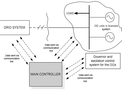
[image:2.612.315.566.345.446.2]A good control strategy is of primary important in ensuring safe operation of islanded system. Fig. 1 shows the concept of control strategy used for islanded operation studies. The control strategy consists of main controller which intelligently controls the whole operation of the island including triggering the governor and excitation control system of the DG to change their operation from grid connected to islanding mode and vice-versa. The main controller receives/ transmits the signal from/to grid system, islanded system and governor and excitation controller of the DG via a good and reliable communication link. It will activate islanding mode of operation based on the monitoring result of the on-going activities within the controlled vicinity. Note that an islanding operation is only feasible with the availability of an advanced smart grid application in the distribution grid network. Thus, the control strategy is performed with the assumption that the communication means, monitoring tools and advanced sensors is accessible within the distribution network vicinity.
Fig. 1 Control Strategy for islanded operation To support the planned islanding operation, the following features are proposed for the main controller:
1) The specified circuit breaker is monitored and any tripping following loss of main or cable fault at any load feeder will initiate an islanding operation. In the studies, instead of using common circuit breakers, Remote Circuit Breaker (RCB) [6] are employed. Following the tripping, transfer trips of related RCB is issued. Signal is also transmitted to governor and excitation controller to switch its operation mode.
2) Specify the islanding area upon receiving tripping signal from the correspond RCB.
3) Remotely re-synchronized the grid and island. For such purpose, step by step procedures are carried out for smooth transition during grid reconnection.
4) Option to switch in a Conventional Load Shedding scheme. It is introduced when the island losing one of its generation.
5) Option to switch in a dynamic braking resistor. It is applied when total power to be dispatched in the islanding area is relatively small than those in grid connected. Quick insertion of this dynamic load immediately after the network is islanded helps to bring down the over frequency value during transient stability response. 6) An algorithm of synchronization process for reconnecting
with the grid is introduced.
B. Governor Controller
[image:2.612.49.297.366.548.2]A key success of the islanding operation is relying on the DG’s governor that specifically performs the speed and active power control of the DG. For hydro power plant, hydraulic-mechanical governor and electro-hydraulic (PID Controllers) are commonly used [16-17]. In Malaysia, most of the plants utilized hydraulic mechanical governor, but when considering islanded system, a better approach is to use governor with PID controller.
Fig. 2 Speed-active power (Pf) control block diagram using PID governor The governor applied for the study is as illustrated in Fig. 2. The controller is designed in two modes of operation; grid connected and islanded. For grid connected operation, fixed power control mode is adopted whereas for islanded operation, isochronous mode is applied. The fixed power mode is represented by the predetermine load reference value whilst the isochronous mode is represented by the PID controller. The PID controller helps to maintain the stability of the islanded system. It is used to bring the speed/frequency and the voltage phasor as close as possible to their reference value, thus facilitate the synchronization process. During transient response, the system frequency for hydro turbine application is controlled to be within the limit of 48Hz-53Hz; otherwise the over/under-frequency protection will trigger and trip off the DG and halt the DG’s operation to avoid the risk of out of phase reclosure.
It was reported that no more than one isochronous mode of generator shall be connected to the same parallel interconnected system [18-19]. Multiple generators operated in isochronous mode might usually ‘fight’ each other to control the system frequency. Thus, the generator which running slightly faster might absorb the entire load and the slightly slower generator might shed its entire load [19]. Consequently, this will cause instability in the system frequency. The possibility of this situation to happen are highly depend on the difference of the gains and time constant used in the PID controller of the governor for each of the generators unit [4]. However, the stable operation could be established with the introduction of isochronous load sharing into the operation system [19]. Load sharing is performed by adding load controller in each of DG’s governor which is indicated as Pset in Fig. 2. After all, should one of the generators operate in the islanded operation trips, the other generators still can regulate the island frequency subject to the load changes are within their capacity. The only problem with this scheme is that it required to re-tuning the PID gains when the nature of loads changes.
For the hydro turbine design, an ideal lossless turbine model is commonly used. The linearized transfer function for the model [18] can be expressed as follows:
∆
∆
1
1 1
2
This transfer function is to represent a change of turbine power output as a response of a change in the gate position. However, for this study, the turbine is modeled using a simple first order model.
C. Excitation Controller
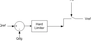
[image:3.612.338.537.229.438.2]The basic requirement of the excitation system is to maintain the machine terminal voltage by automatically regulate the synchronous generator field current including during disturbances [18]. In conjunction with this, IEEE has produced several recommendation excitation system models to cater different purposes. With regards of the recommendation, the PSCAD/EMTDC software has facilitated their users with the excitation models in its standard library. The IEEE type SCRX solid state exciter model has been chosen for the study. The output field voltage is regulated by the control system of the exciter in order to maintain the system voltage at Vref. The control block diagram developed for this study to control the Vref value is as illustrated in Fig. 3.
Fig. 3 Voltage-reactive power(Qv) control block diagram
During normal operation/grid connected, the AVR regulate the excitation voltage to control and maintain the desired reactive power flow value. In this case, the reactive power predetermined value is fed to the Vref input signal. When switches to the islanding operation mode, the AVR is switched
to voltage control mode. It tries to keep the terminal voltage equal to its reference value of 1 pu or in other words to maintain the voltage level within the permissible value. This helps to sustain the islands operation, thus allow safe grid reconnection process.
III. CASESTUDIES
A. Introduction
[image:3.612.100.250.588.657.2]In this study, a well planned islanding operation is performed on a distribution network indicated in Fig. 4. The aim of this study is to investigate the transient response of the DGs when a part of the network is islanded with a proper planned islanding operation. The control strategy discussed in Section II is implemented in this islanding operation.
Fig. 4 Distribution network under study
The network shown in Fig. 4 consists of two mini hydro generation units rated 2MVA operated in 3.3kV voltage level. Both DGs are equipped with the governor and excitation controller as described in the previous section of this paper. Two parallel units of 2MVA generator transformer are connected to the DGs to stepping up the voltage level to 11kV. The distribution network is connected to the transmission grid via two parallel step up transformer (11kV/132kV) rated 30MVA. A number of load feeders (with 2.2MW total load amount) are connected together in the network. As indicated in Fig. 4, a Normal Off Point (NOP) for 11kV subsystem is located at the intersection of two load feeders. As for islanding studies purposes, circuit breakers are located at several strategic points. The status of these circuit breakers will be monitored by the main controller.
B. Simulation studies
The network shown in Fig.4 is developed using EMTDC/PSCAD simulation package. The
unit is represented by PSCAD/EMTDC synchronous generator model with the proposed governor and excitation
Meanwhile, the loads are represented by static type of PSCAD/EMTDC load model. In this study, the system is assumed to have its own islanding detection technique detect any abnormality in the system. Thus, i
operation is simulated with the opening of circuit breaker at t=15s. There are two possible islanding areas
considered for this study. Fig. 5 and Fig. islanding area 1 and area 2 respectively. Prior to
operation, a proper islanding strategies need to be planned to avoid operation risk and failure.
Fig. 5 Islanding area 1
Fig. 6 Islanding area 2
Different fault locations have lead to different islanding area which then creates a different operating condition indicated in Fig. 5, the islanding area 1 is formed with the opening of main circuit breaker inter tie the studied network with the grid transmission. The opening of the circuit breaker is assumed to be due to loss of main. The failed circuit breaker developed using The hydro generation is represented by PSCAD/EMTDC synchronous generator and excitation controller. Meanwhile, the loads are represented by static type of In this study, the system is assumed to have its own islanding detection technique to ystem. Thus, islanding the opening of circuit breaker at islanding areas that are being . 6 highlight the Prior to islanding operation, a proper islanding strategies need to be planned to
to different islanding nt operating condition. As area 1 is formed with the the studied network The opening of the circuit breaker is assumed to be due to loss of main. The failed circuit breaker
will then trigger a transfer trip to the other four circuit
breakers which protect the power transformers
Simultaneously, the normally opened bus section i
close state to interconnect two load feeders, thus allow the DGs to continuously serve all the loads in the
network. For this case, the turbines are forced to accelerate as the total dispatched power reduces from 3.0MW (during normal operation) to 2.4MW (during islanding operation). the bus section left opened, the loads located at the right side of the network till the NOP will be disconnected
cause the loads to loss their power supply islanding operation.
As illustrated in Fig 6, the islanding area 2 is formed due to the opening of two circuit breakers (as
Those circuit breakers are assumed to trip due to a cable fault at one of the load feeder. For this case, the DGs keep continuously dispatch power to a quarter of the
indicated in Fig 6.The loads in the right hand receive power from the grid. The
are 0.72MW. Note that the DGs have to reduce their power output from 3.0MW to 0.72MW. They
more as the power imbalance is huge. system during transient response is found to be
maximum allowable frequency. This obviously requires dynamic braking resistor to bring down the speed of the turbine. Thus, a dynamic braking resistor rated 1.5MW is connected to the 11kV power plant feeder.
activated upon receiving signal from the main controller immediately after detecting total power dispatched islanding area is less than its critical value.
The challenge with the hydro governor transient response. It takes approximately 20s speed to reach its normal value. Thus,
proper planned islanding operation to achieve a seamless grid reconnection. The followings are the procedure
simulate a successful islanding operation:
1. At t =15s, islanding operation is simulated.
2. At t = 60s, dead line charging is applied to the tripped breaker/breakers located at the grid side.
3. At t = 75s, voltage phasor of the island is controlled to initiate synchronization with the grid.
4. At t = 90s, reconnection process with the grid is simulated.
These procedures are simulated with an
fault is cleared several seconds after the opening of circuit breaker. Each time procedure may
on the status of fault. The synchronization the simulation follows the principle operation synchronizing check relay[20]. The synchronization applied in the study is as follows:
∆v = Voltage difference (±10%) ∆f = Frequency difference (125 MHz) ∆θ = Phase Angle Difference (25˚)
C. Simulation Results and Discussion
Islanding operation for area 1 and area 2 are simulated and the results such as shown in Fig. 7 and Fig.
transient response of the islanded system is observed. that the transient response for the first 5 seconds of simulation
trigger a transfer trip to the other four circuit the power transformers. Simultaneously, the normally opened bus section is set to a close state to interconnect two load feeders, thus allow the DGs to continuously serve all the loads in the distribution For this case, the turbines are forced to accelerate as the total dispatched power reduces from 3.0MW (during l operation) to 2.4MW (during islanding operation). If the bus section left opened, the loads located at the right side of the network till the NOP will be disconnected. This will power supply throughout the
, the islanding area 2 is formed due to breakers (as denoted in red color). Those circuit breakers are assumed to trip due to a cable fault For this case, the DGs keep continuously dispatch power to a quarter of the total loads as The loads in the right sides on the other The total loads in the area Note that the DGs have to reduce their power 3.0MW to 0.72MW. They are forced to accelerate more as the power imbalance is huge. The frequency of the system during transient response is found to be higher than the This obviously requires a dynamic braking resistor to bring down the speed of the braking resistor rated 1.5MW is connected to the 11kV power plant feeder. This resistor is only activated upon receiving signal from the main controller total power dispatched in the critical value.
governor turbine is its slow approximately 20s-30s for the speed to reach its normal value. Thus, it is essential to have a proper planned islanding operation to achieve a seamless grid reconnection. The followings are the procedures used for
operation: At t =15s, islanding operation is simulated.
charging is applied to the tripped breaker/breakers located at the grid side.
At t = 75s, voltage phasor of the island is controlled to initiate synchronization with the grid.
At t = 90s, reconnection process with the grid is
with an assumption that the fault is cleared several seconds after the opening of circuit procedure may vary accordingly depends The synchronization process applied in ciple operation used for a . The synchronization setting
∆f = Frequency difference (125 MHz)
and Discussion
0 20 40 60 80 100 ... ... ... 0.00 0.50 1.00 1.50 2.00 2.50 3.00 A C T IV E P O W E R ( M W )
Active Pow er DG1 Active Pow er DG2
47.0 48.0 49.0 50.0 51.0 52.0 53.0 F R E Q U E N C Y ( H z )
Speed DG1 Speed DG2
0 20 40 60 80 100 ...
... ... -0.50 0.00 0.50 1.00 1.50 2.00 2.50 R E A C T IV E P O W E R ( M V A R )
Reactive Pow er DG1 Reactive Pow er DG1
0.750 0.800 0.850 0.900 0.950 1.000 1.050 V O L T A G E T E R M IN A L ( P U )
Voltage terminal DG1 Voltage Terminal DG2
0 20 40 60 80 100 ...
... ... -10 0 10 20 30 40 50 60 P h a s e ( d e g re e ) PhaseTX1 Phase_grid
0 20 40 60 80 100 ...
... ... -0.50 0.00 0.50 1.00 1.50 2.00 2.50 R E A C T IV E P O W E R ( M V A R )
Reactive Pow er DG1 Reactive Pow er DG1
0.700 0.750 0.800 0.850 0.900 0.950 1.000 1.050 V O L T A G E T E R M IN A L ( P U )
Voltage terminal DG1 Voltage Terminal DG2
0 20 40 60 80 100 ...
... ... -200 -150 -100 -50 0 50 100 150 200 P h a s e ( d e g re e ) Phase1013 Phase_1012
0 20 40 60 80 100 ...
... ... 0.00 0.50 1.00 1.50 2.00 2.50 3.00 A C T IV E P O W E R ( M W )
Active Pow er DG1 Active Pow er DG2
47.0 48.0 49.0 50.0 51.0 52.0 53.0 F R E Q U E N C Y ( H z )
Speed DG1 Speed DG2
is due to machine initialization process to synchronize with the grid. In addition, note that both DGs are identical, hence their response are identical as well. Upon detecting the opening of the main circuit breaker, the DG’s governor and excitation control unit switch their control strategy from PQ mode to Vf control mode. As can be observed in Fig. 7, the active power generate by each of the DG during normal operation is 1.5MW, make up to 3.0 MW in total. Immediately after the system islanded, the active power for both DGs reduce to match the loads in the island (i.e. 2.4MW). The power is shared equally as both DGs are identical. For non-identical DGs, the power will be shared proportionally based on the rating of teach DG unit. Meanwhile, in response to the reduced power output, the system frequency increases to 52.5Hz and then slowly recovers to 50Hz. It takes about 25s for the DGs to reach its nominal value. Most importantly, this frequency transient response is still within an acceptable operation range. As for voltage response, the terminal voltage for the DGs decreases as the DGs dispatch more reactive power to the islanded system. The voltage deviation however is still within the range of 0.95p.u and 1.05 p.u. The voltage recovers and reaches its steady state much faster than the frequency. Note that simulation results recorded the response for each of the islanding simulation procedures previously mentioned. It can be observed that the deviation of frequency, voltage, active and reactive power at 60s and 75s of simulation time is unnoticeable. The islanded system phase angle at the reconnection point as shown in Fig.7 is successfully controlled by the governor to be as close as possible to the grid phase angle. Thus, the three requirements (the frequency, voltage and phase angle for the islanded system closely match those in the grid side) to synchronize with the grid have been fulfilled making the grid reconnection process is smoothly implemented. This can be verified by looking at the response of the DGs during grid reconnection at t = 90s. At this point of time, the governor and excitation controller switch their operation to grid connected and DGs successfully restore their supply to the loads in the distribution network.
[image:5.612.341.540.50.385.2]The response of the DGs during islanding operation in islanding area 2 is approximately the same as the response in islanding area 1. This is due to the quick insertion of the dynamic braking resistor to the islanded system. Without the resistor, the transient response for the system frequency steeply increase to 58Hz which will trigger the over frequency protection and eventually trip the DGs operation. Theoretically, the first half cycle of the transient response came from a prompt reaction from the swing equation. Controlled governor and excitation start to operate later. The only way to lower the frequency value is to put the resistor as quickly as possible. As can be seen in Fig. 8, after the transient time, the active power response is stabled at 1.1MW, or 2.2MW in total (0.7MW+1.5MW). The phase angle plot recorded totally different response as the measured point is differed to the one in islanding area 1. Likewise, the governors manage to control the phase angle, hence lead to the successful grid reconnection process.
Fig 7 Simulation results for islanding operation in area 1
[image:5.612.341.542.422.712.2]IV. CONCLUSIONS
In this paper, an effective approach to control a planned islanding operation in a smart grid distribution system has been discussed. The approach used a main
capable to intelligently coordinate the islanding operation different islanding area via a smart grid technology. simulation study has been developed to investigate the effectiveness of the controller for the islanding operation. Prior to the simulation, a well planned islanding operation for two defined islanding areas has been established simulation results showed that the controller capable to automatically perform the islanding operation
the islanded system was formed. Despite of the nat hydro governor turbine to have a slow response,
demonstrated a good performance throughout islanding operation. The speed during transient time was well regulated by the governor and the PID controller has managed to bring the frequency to its nominal value. The phasor
controlled to be closely matched to the grid side. have led to establish synchronization between island thus allowed a seamless grid reconnection.
V. ACKNOWLEDGEMENT
The authors would like to thank Dr.Sallehuddin Yusof from the Advanced Power Solution Sdn. Bhd. for his ideas and consistent support towards this research work.
VI. REFERENCES
[1] F. Katiraei, et al., "Planned islanding on rural feeders ; perspective," in Power and Energy Society General Meeting Conversion and Delivery of Electrical Energy in the 21st Century, 2008 IEEE, 2008, pp. 1-6.
[2] L. Seca and J. A. Pecas Lopes, "Intentional islanding for reliability improvement in distribution networks with high DG penetration," in Future Power Systems, 2005 International Conference on
1-5.
[3] I. Balaguer-Alvarez, et al., "Control for Grid
Intentional Islanding Operations ofDistributed Power Generation," Industrial Electronics, IEEE Transactions on, vol. PP, pp. 1
[4] C. F. Ten and P. A. Crossley, "Control of multiple distributed generators for intentional islanding," in SmartGrids for Distribution, 2008. IET-CIRED. CIRED Seminar, 2008, pp. 1
[5] P. Lund, "The Danish Cell Project - Part 1: Background and General Approach," in Power Engineering Society General Meeting, 2007. IEEE, 2007, pp. 1-6.
[6] R. Caldon, et al., "Feasibility of adaptive intentional islanding operation of electric utility systems with distributed generation," Electric Power Systems Research, vol. 78, pp. 2017
[7] S. Conti, et al., "Generators control systems in intentionally islanded MV microgrids," in Power Electronics, Electrical Drives, Automation and Motion, 2008. SPEEDAM 2008. International Symposium on 2008, pp. 399-405.
[8] F. Pilo, et al., "Improvement of reliability in active networks with intentional islanding," in Electric Utility Deregulation, Restructuring and Power Technologies, 2004. (DRPT 2004). Proceedings 2004 IEEE International Conference on, 2004, pp. 474
[9] I. J. Balaguer, et al., "Intelligent control for intentional islanding operation of microgrids," in Sustainable Energy Technologies, 2008. ICSET 2008. IEEE International Conference on
[10] J. A. P. Lopes, et al., "Defining control strategies for MicroGrids islanded operation," Power Systems, IEEE Transactions on, pp. 916-924, 2006.
In this paper, an effective approach to control a planned islanding operation in a smart grid distribution system has a main controller that coordinate the islanding operation for smart grid technology. A simulation study has been developed to investigate the islanding operation. l planned islanding operation for two defined islanding areas has been established. The showed that the controller capable to the islanding operation for which area Despite of the nature of the slow response, it has demonstrated a good performance throughout islanding The speed during transient time was well regulated by the governor and the PID controller has managed to bring o its nominal value. The phasor was also well controlled to be closely matched to the grid side. Those factors establish synchronization between the grid and
seamless grid reconnection.
MENT
Dr.Sallehuddin Yusof from the Advanced Power Solution Sdn. Bhd. for his ideas and
this research work.
, "Planned islanding on rural feeders ; utility Power and Energy Society General Meeting - Conversion and Delivery of Electrical Energy in the 21st Century,
L. Seca and J. A. Pecas Lopes, "Intentional islanding for reliability ution networks with high DG penetration," in Future Power Systems, 2005 International Conference on, 2005, pp. , "Control for Grid-connected and Intentional Islanding Operations ofDistributed Power Generation," vol. PP, pp. 1-1, 2010. C. F. Ten and P. A. Crossley, "Control of multiple distributed
SmartGrids for Distribution, , 2008, pp. 1-4.
Part 1: Background and General Power Engineering Society General Meeting, 2007.
, "Feasibility of adaptive intentional islanding h distributed generation," vol. 78, pp. 2017-2023, 2008. , "Generators control systems in intentionally islanded
Power Electronics, Electrical Drives, Automation DAM 2008. International Symposium on, , "Improvement of reliability in active networks with Electric Utility Deregulation, Restructuring and Power Technologies, 2004. (DRPT 2004). Proceedings of the
, 2004, pp. 474-479 Vol.2. , "Intelligent control for intentional islanding
Sustainable Energy Technologies, 2008. on, 2008, pp. 898-903. , "Defining control strategies for MicroGrids Power Systems, IEEE Transactions on, vol. 21,
[11] X. Ding, "Synchronized Phasor Measurement and Islanding Operation of Distributed Generation," Doctor of Philosophy, Faculty of Engineering, The Queen's University Belfast, 2006.
[12] G. Chicco and P. Mancarella, "Distributed multi
comprehensive view," Renewable and Sustainable Energy Reviews, vol. 13, pp. 535-551, 2009.
[13] R. J. Best, et al., "Management of a multiple
in Power & Energy Society General Meeting, 2009. PES '09. IEEE 2009, pp. 1-6.
[14] F. Katiraei and M. R. Iravani, "Power Management Strategies for a Microgrid With Multiple Distributed Generation Units," Systems, IEEE Transactions on, vol. 21, pp. 1821
[15] R. Majumder, et al., "Control of parallel converters for load sharing with seamless transfer between grid connected and islanded modes," in Power and Energy Society General Meeting
Delivery of Electrical Energy in the 21st Century, 2008 IEEE pp. 1-7.
[16] N. Kishor, et al., "A review on hydropower plant models and control," Renewable and Sustainable Energy Reviews,
776-796, 2007.
[17] C. Yin Chin, et al., "Modelling of hydraulic turbine for dynamic studies and performance analysis," in Power Engineering Conference, 2007. AUPEC 2007. Australasian Universities, 2007, pp. 1
[18] P. Kundur, Power System Stability 1994.
[19] L. L. J. Mahon, Diesel Generator Handbook: Oxford;Butterworth Heinemn, 1992.
[20] R. M. A.H.Abu Bakar, S.J.Alias, "Autoreclose Performance on 275kV and 132kV Transmission Line," TNBT Technical Workshop, 2000.Biographies
Hasmaini Mohamad was born in Kota Bharu,Kelantan, Malaysia in 1976. In 1999 and 2004, she received the Bsc and MsEng degrees respectively from the University Of Malaya, Malaysia where she is currently pursuing her PhD degree. Her major research interest include islanding operation of distributed generation, hydro pow
system, load sharing technique, and load shedding scheme.
Ab halim bu Bakar
Engineering in 1976 from Southampton University UK and M.Eng. and PhD from University Technology Malaysia in 1996 and
experience in Malaysia before joining academi Currently he is a Lecturer in the Department of Electrical Engineering, University of Malaya, Malaysia. Dr. Halim is a Member of
Chartered Engineer. His resear power system protection and power system transient.
Hew Wooi Ping was born in Kuala Lumpur, Malaysia in 1957. He obtained his Bachelor of Engineering (Electrical) degree in 1981, and his Master of Electrical Engineering degree from U
Malaysia. He later obtained his PhD from University of Malaya, Malaysia in 2000.
at the Department of Electrical Engineering, University of Malaya. Dr. Hew is a Member of IET and a Chartered Engineer. H
electrical drives, electrical machine design, and application of fuzzy logic/neural network to electrical-machine-related applications.
Hazlie Mokhlis received his B. Eng in Electrical Engineering in 1999 and M. Eng. Sc in 2002 from University of Malaya, Malaysia. His obtained PhD degree from the University of Manchester, UK in 2009. Currently he is a Lecturer in the Department of Electrical Engineering,
research interest is in distribution automation area and power system protection.
X. Ding, "Synchronized Phasor Measurement and Islanding Distributed Generation," Doctor of Philosophy, Faculty of Engineering, The Queen's University Belfast, 2006.
G. Chicco and P. Mancarella, "Distributed multi-generation: A Renewable and Sustainable Energy Reviews,
, "Management of a multiple-set synchronous island," Power & Energy Society General Meeting, 2009. PES '09. IEEE, F. Katiraei and M. R. Iravani, "Power Management Strategies for a tiple Distributed Generation Units," Power
vol. 21, pp. 1821-1831, 2006. , "Control of parallel converters for load sharing with seamless transfer between grid connected and islanded modes," nd Energy Society General Meeting - Conversion and Delivery of Electrical Energy in the 21st Century, 2008 IEEE, 2008, , "A review on hydropower plant models and Renewable and Sustainable Energy Reviews, vol. 11, pp. , "Modelling of hydraulic turbine for dynamic studies and performance analysis," in Power Engineering Conference, 2007. AUPEC 2007. Australasian Universities, 2007, pp. 1-6. P. Kundur, Power System Stability and Control: McGraw Hill Inc, L. L. J. Mahon, Diesel Generator Handbook: Oxford;Butterworth-R. M. A.H.Abu Bakar, S.J.Alias, "Autoreclose Performance on 275kV and 132kV Transmission Line," TNBT Technical Workshop,
was born in Kota Bharu,Kelantan, 1976. In 1999 and 2004, she received the Bsc and MsEng degrees respectively from the University Of Malaya, Malaysia where she is currently pursuing her PhD degree. Her major research interest include islanding operation of distributed generation, hydro power plant operating system, load sharing technique, and load shedding
Ab halim bu Bakar received his B.Sc. in Electrical Engineering in 1976 from Southampton University UK and M.Eng. and PhD from University Technology 1996 and 2003. He has 30 years of utility experience in Malaysia before joining academia. Currently he is a Lecturer in the Department of Electrical Engineering, University of Malaya, Malaysia. is a Member of IEEE, CIGRE, IET and a Chartered Engineer. His research interests include
ransient.
Hew Wooi Ping was born in Kuala Lumpur, Malaysia in 1957. He obtained his Bachelor of Engineering (Electrical) degree in 1981, and his Master of Electrical Engineering degree from University of Technology Malaysia. He later obtained his PhD from University of Malaya, Malaysia in 2000. He is an Associate Professor at the Department of Electrical Engineering, University Dr. Hew is a Member of IET and a Chartered Engineer. His research interests include electrical drives, electrical machine design, and application of fuzzy
related applications.