International Journal of Emerging Technology and Advanced Engineering
Website: www.ijetae.com (ISSN 2250-2459,ISO 9001:2008 Certified Journal, Volume 5, Issue 6, June 2015)
440
Wireless Power Transfer
Somashekar.B
1, David Livingston.D
21,2Asst Professor, Dr. T. Thimmaiah Institute of Technology, KGF
Abstract—Wireless power transfer (WPT) is the propagation of electrical energy from a power source to an electrical load without the use of interconnecting wires. It is becoming very popular in recent applications. Wireless transmission is useful in cases where interconnecting wires are difficult, hazardous, or non-existent. Wireless power transfer is becoming popular for induction heating, charging of consumer electronics (electric toothbrush, charger), biomedical implants, radio frequency identification (RFID), contact-less smart cards, and even for transmission of electrical energy from space to earth.
In the design of the coils, the parameters of coils are obtained by using the basic calculations and measurements.
The experimental results are presented and verified by using the MATLAB programming for the input and output wave forms.
Keywords—Wireless power transfer, Electromagnetic Induction, MATLAB.
I. INTRODUCTION
The goal of the present research is to develop a method of wireless power transmission. The idea of wireless power transfer originated from the inconvenience of having too many wires sharing a limited amount of power sockets. We believe that many people have the same experience of lacking enough sockets for their electronic organized. Wireless power transfer can be divided into two major types – electromagnetic induction and electromagnetic radiation. Electromagnetic induction can be of three type’s electrodynamics, electrostatic and evanescent wave coupling. Electromagnetic radiation can be divided into two categories – microwave power transfer (MPT) and laser.
Electromagnetic Induction: It is the production of an induced voltage in a circuit which is excited by means of the magnetic flux. The condition for an induced current to flow in a closed circuit is that the conductors and the magnetic field must rotate relative to each other
Electromagnetic Radiation: Electromagnetic radiation travels through vacuum at the speed of light and propagates by the interaction of time varying electric and magnetic fields. It has a wavelength and a frequency.
There are a number of limitations to the full implementation of wireless energy transfer:
a) Size: The size of the transmitter or the receiver sometimes becomes too large to implement in a smaller system devices. Thus by creating a wireless power transfer system, it would help clean up the clutter of wires around power sockets making the space more tidy and
b) Range: The range of wireless energy transfer is just a few meters, which represents a major hurdle towards its practical implementation.
c) Efficiency: Typical efficiency of wireless energy transfer ranges between 45% and 80% and is less efficient than conventional wire based energy transfer methods.
In our experiment we have considered electro dynamic or inductive coupling. An inductive link is formed by a loosely coupled transformer consisting of a pair of coils that are usually placed in a coaxial arrangement .The external or the primary coil is excited by an alternating current, and thus an electromagnetic field is produced with its magnitude dependent on the dimensions of the coil, the drive current and the frequency of operation. A portion of the alternating flux lines generated this way link to the internal or the secondary coil, and the change in flux linkage produces a voltage in the secondary coil, which is proportional to the rate of change of the flux and the number of turns in the secondary coil (Faraday’s law of
electromagnetic induction). If the number of turns is n and
the magnetic flux linking each turn is ψm, then the induced
voltage for the circuit can be written as, v=n (d ψm/dt).
Hardware design for different turns in the receiver and transmitter coil is shown and the MATLAB programming is written for the input and output, finally the comparative graph is plotted and checked for input and output of hardware and programming.
II. BLOCK DIAGRAM
International Journal of Emerging Technology and Advanced Engineering
Website: www.ijetae.com (ISSN 2250-2459,ISO 9001:2008 Certified Journal, Volume 5, Issue 6, June 2015)
441
A.Source: The supply given here is 5V(DC).
B.Booster circuit: A booster circuit is a DC-DC power converter with an output voltage greater than its input voltage. It is of switched-mode power supply (SMPS) containing one semiconductor (a transistor), at least one energy storage element, a capacitor, an inductor, or the two in combination.
C.Transmitter coil: The transmitter coil is the one which transmits power wirelessly to the receiver coil.
D.Receiver coil: The receiver coil is the one which receives power from the transmitter coil. The receiver coil consists of filter circuit.
E.Load: The load is an LED.
III. EXPERIMENT
Fig.2 Circuit Diagram of a Wireless Power Transfer System
The fig. 2 shows the circuit diagram of a wireless power transfer system. The input power to the system is DC supply of 5V is given. The booster circuit is also known as (boost converter or step-up converter) is a DC-DC power converter with an output voltage greater than its input voltage. It is a switched-mode power supply (SMPS) containing one semiconductor (a transistor) and at least one energy storage element, a capacitor, inductor, or the two in combination. Booster circuit also power devices at small scale applications, such as portable lighting systems. A LED typically requires 3.3V to emit light. The transmitter coil made up of copper turns of American Wire Gauge (AWG) of 18 is used to transmit power wirelessly to the receiver coil. The receiver coil is also made up of same wire gauge as transmitter coil.
The magnetic field generated by the transmitter coil couples with the receiver coil, exciting the coil and causing energy to build up in it. This energy is coupled out of the receiver coil to do useful work, for example, directly powering a load. The LED is used as a load. Filters made of capacitor (sometimes in combination with inductors) is used to the output to reduce output voltage ripple. The transmitter coil and receiver coil is constructed with 4.5cm radius and we have constructed both coils with 8 turns.
Specifications
Transmittercoil Side Input voltage=5Volts
BD139Transistor
R = 1.5KΩ
C1 =470pF
C2=4.7nF
C3=100nF
Turns = 8
Receiver Coilside
D1 (IN4148)
C4 = 4.7nF
Turns = 8
Model picture for 8 turns (single load)
International Journal of Emerging Technology and Advanced Engineering
Website: www.ijetae.com (ISSN 2250-2459,ISO 9001:2008 Certified Journal, Volume 5, Issue 6, June 2015)
442
[image:3.612.51.285.122.682.2]IV. EXPERIMENTAL RESULTS
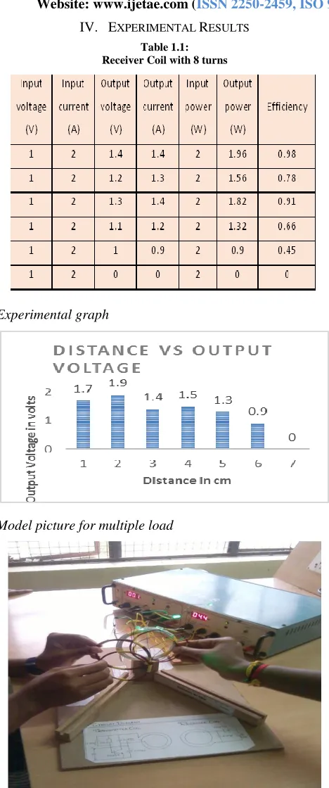
Table 1.1: Receiver Coil with 8 turns
Experimental graph
[image:3.612.60.281.133.340.2]Model picture for multiple load
Fig. iv Model picture of a Wireless Power Transfer System for multiple load
Table 1.2:
Receiver Coil of (8, 10, 15 turns)
Experimental graph
1.9 1.7
0.9 0
0 1 2
1 2 3 4
O
u
tp
u
t
V
o
lt
age
in
V
o
lt
s
Distance in cm
D I S TA N C E V S O U T P U T
V O LTAG E
V. MATLAB PROGRAMMING
MATLAB is a high-performance language for technical computing. It integrates computation, visualization, and programming in an easy-to-use environment where problems and solutions are expressed in familiar mathematical notation. Typical uses include Math and computation Algorithm development Data acquisition Modeling, simulation, and prototyping Data analysis, exploration, and visualization Scientific and engineering graphics Application development, including graphical user interface building.
[image:3.612.327.551.145.448.2]International Journal of Emerging Technology and Advanced Engineering
Website: www.ijetae.com (ISSN 2250-2459,ISO 9001:2008 Certified Journal, Volume 5, Issue 6, June 2015)
443
Today, MATLAB engines incorporate the LINPAC and blast libraries, embedding the state of the art in software for matrix computation. MATLAB has evolved over a period of years with input from many users. In university environments, it is the standard instructional tool for introductory and advanced courses in mathematics, engineering, and science. In industry, MATLAB is the tool of choice for high-productivity research, development, and
analysis.
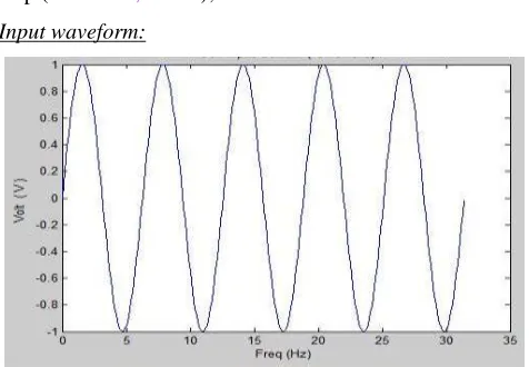
Input Program for an wireless power transfer system
[image:4.612.49.287.349.514.2]t = 0:.1:pi * 10; y = sin(t); figure plot(t,y);
xlabel ('Freq (Hz) ');
ylabel ('Volt ( V ) ');
title (' Coil Input Voltage(Sine wave)');
disp ('Dr. TTIT, Kolar');
Input waveform:
Output Program for an wireless power transfer system vo = 1;
c = 45e-6; r = 1800; f = 50; tf = 70e-3; w = 2 * pi * f; t = 0:0.05e-3:tf; n = length (t);
state = 'on';
fori = 1:n
vs(i) = vo * sin(w * t(i));
switch state
case'on' vr(i) = vs(i); ir = vs(i)/r;
ic = w * c * vo * cos(w * t(i));
sumi = ir + ic;
ifsumi<= 0
state = 'off'
ta = t(i);
end case'off'
vr (i) = vo * sin (w * ta) * exp(-(t(i) - ta)/(r * c));
ifvs(i) >= vr(i)
state = 'on';
end end end
plot (t, vs, ':',t,vr, 'k','linewidth',5)
xlabel('Time (s)');
ylabel ('Voltage (v)');
Output Waveform:
Program for Magnetic field distribution
clc clear
closeall
%Define global variables global u0
u0=4*pi*1e-7; %permeability of free space
%Define coil parameters
I0=1; %Coil current in Amps
a=.1; %Coil radius in m
x_p=0; y_p=0; z_p=0; %Define coordinates of coil center
point
%First we see how to calculate the magnetic field at a single point in
%space
%Input test point
International Journal of Emerging Technology and Advanced Engineering
Website: www.ijetae.com (ISSN 2250-2459,ISO 9001:2008 Certified Journal, Volume 5, Issue 6, June 2015)
444
[Bx,By,Bz]=
magnetic_field_current_loop(x,y,z,x_p,y_p,z_p,a,I0)
%Now showing how to calculate points along a straight line
clearxyz
%Input vector of points
x=0; y=0; z=linspace(0,.25,100); %These default
coordinates calculates the magnetic field along the z axis through the center of the coil
[Bx,By,Bz] =
[image:5.612.322.574.138.488.2]magnetic_field_current_loop(x,y,z,x_p,y_p,z_p,a,I0); figure
plot(z,Bz)
xlabel('z [m]')
ylabel('Bz [T]')
title('1D magnetic field tests')
%now we test how to calculate a 2D grid of points
clearxyz
%input mesh of points in 2D plane
x=0;[y,z]=meshgrid(linspace(-.05,.05,25),linspace(0,.1,25)); %this is a 2d plane over the
x=0 plane that extends away from the coils in the yz plane.
[Bx,By,Bz] =
magnetic_field_current_loop(x,y,z,x_p,y_p,z_p,a,I0);
figure
surf(y,z,Bz)
xlabel('y [m]')
ylabel('z [m]')
zlabel('Bz [T]')
title('2D magnetic field tests')
colorbar%addcolorbar
shadingflat%Removes black lines from the mesh
Simulates the magnetic field distributions in a given X-Y-Z plane - 3D Space Model. You can change the parameters for example, number of turns, radius of the coil etc. can be changed and simulate the magnetic field distributions. Simulation of Vector Field Usage of Biot Steverts Law for magnetic Field Simulations. Between Two thin Parallel Conductors lying on XY plane @ origin (Z=0)..Field distribution is calculated on XZ plane @ origin (Y=0)..
Output for the magnetic field distribution in 1D.
Magnatic field distribution in 2D Plane
PROGRAM FOR CURRENT LOOPS IN MAGNETIC FIELD
clc clear
closeall
%Define global variables global u0
u0=4*pi*1e-7; %permeability of free space
%Define coil parameters
I0=1; %Coil current in Amps
a=.1; %Coil radius in m
x_p1=0; y_p1=0; z_p1=0; %Define coordinates of coil 1
International Journal of Emerging Technology and Advanced Engineering
Website: www.ijetae.com (ISSN 2250-2459,ISO 9001:2008 Certified Journal, Volume 5, Issue 6, June 2015)
445
x_p2=0; y_p2=0; z_p2=a; %Define coordinates of coil 2
center point
%input mesh of points in 2D plane
x=0; [y,z]=mesh grid(line space(-.05,.05,25),line
space(0,.1,25)); %this is a 2d plane over the x=0 plane that
extends away from the coils in the yz plane.
[Bx1,By1,Bz1] =
magnetic_field_current_loop(x,y,z,x_p1,y_p1,z_p1,a,I0);
%Calculate field from first coil
[Bx2,By2,Bz2] =
magnetic_field_current_loop(x,y,z,x_p2,y_p2,z_p2,a,I0);
%Calculate field from second coil %Add the components
Bx=Bx1+Bx2; By=By1+By2; Bz=Bz1+Bz2;
%Calculate the magnitude of the vector
[image:6.612.361.532.125.264.2]B_mag=sqrt(Bx.^2+By.^2+Bz.^2); figure
surf(y,z,B_mag)
xlabel('y [m]')
ylabel('z [m]')
zlabel('B [T]')
title('2D Magnetic Field Distributions')
colorbar
shadingflat
Output for the Current loop in 2D Plane
VI. COMPARISION OF PROGRAMMING WITH
EXPERIMENTAL RESULTS
By changing the parameters for example, number of turns of the transmitter and receiver coil, radius of the coil etc. can be changed and the magnetic field distributions programming of Vector Fields Usage of Biot Steverts Law for Magnetic Field Two circular Helmholtz coil at the center of the uniform field. The experimental values is being compared with the programming values.
VII. CONCLUSION
More reliable than ground based solar power. If we develop this, we need not bother about the exhaustion of natural resources. If this project succeeds it will become a boon to next generations. Transmission without wires-a reality. Efficient, Low maintenance cost. But, high initial cost. Better than conventional wired transfer. Energy crisis can be decreased. Low loss. In near future, world will be completely wireless. WPT emerges out as the best alternative for efficient power transmission despite its few drawbacks such as very high installation cost. WPT has very high efficiency as the loss during power transmission is nearly negligible and it acts as a boon for the people of those areas where wired transmission is not possible. The power failure due to short circuit and electric faults would not be possible at all. Only need a simple design to efficiently transfer large power levels over moderate distances.
VIII. FUTURE ASPECTS
International Journal of Emerging Technology and Advanced Engineering
Website: www.ijetae.com (ISSN 2250-2459,ISO 9001:2008 Certified Journal, Volume 5, Issue 6, June 2015)
446
Furthermore, the impedance matching between the loop and coil embodied by the coupling constant suggest that a discrete matching network can be used to directly connect the source/load to the coils, thereby simplifying the system. Clearly the advantages of high and near constant transfer efficiency at mid-range distance compared to near-field and far-field techniques make this technology exciting for many applications. There is any number of low power wireless recharging scenarios that would benefit from increased range vs. efficiency at power levels typically used in RFID. Finally this paper has focused on the delivery aspect of RF power while consumer electronics require DC power for operation and recharging. Adaptive rectifier designs will need to be developed that do not interfere with the operation of the magnetically coupled resonators.
REFERENCES
[1] S. Ahson and M. Ilyas, RFID handbook: applications, technology, security, and privacy. Boca Raton: CRC Press, 2008.
[2] N. Fletcher and T. Rossing, The Physics of Musical Instruments. Springer-Verlag, 1998.
[3] R. Mongia, RF and Microwave Coupled-Line Circuits. City: Artech House Publishers, 2007.
[4] J. Chen, Feedback Networks: theory and circuit application. City: World Scientific Publishing Company, 2007.
[5] Adaptive Tuning - Expectations and Limitations by John Gerry, ExperTune Inc. www.expertune.com © 2005 ExperTune Inc. [6] WREL (Wireless Resonant Energy Link) (c) 2011, all rights
reserved. Contact: Professor Joshua R. Smith, [email protected] [7] Adaptive Impedance Matching for Magnetically Coupled Resonators
Benjamin H. Waters1, Alanson P. Sample1; 2, and Joshua R. Smith1; 2Department of Electrical Engineering, University of Washington,
USA
[8] Zia A. Yamayee and Juan L. Bala, Jr., ―Electromechanical Energy Devices and Power Systems‖, John Wiley and Sons, 1947, p. 78
[9] Simon Ramo, John R. Whinnery and Theodore Van Duzer, ―Fields and Waves in Communication Electronics‖, John Wiley & Sons, Inc.; 3rd edition (February 9, 1994)
[10] S. Kopparthi, Pratul K. Ajmera, "Power delivery for remotely located Microsystems," Proc. of IEEE Region 5, 2004 Annual Tech. Conference, 2004 April 2, pp. 31-39.
[11] Tomohiro Yamada, Hirotaka Sugawara, Kenichi Okada, Kazuya Masu, andAkio Oki, "Battery-less Wireless Communication System through Human Body for invivo Healthcare Chip,"IEEE Topical Meeting on Silicon Monolithic Integrated Circuits in RF Systems‖ [12] ―Category: Radio spectrum -Wikipedia, the free encyclopedia,‖
[online document], 2004Aug26[cited12/11/04] http://en.wikipedia.org/wiki/Category:Radio_spectrum.
AUTHORS
SOMASHEKAR. B received B.E degree (Electrical & Electronics Engineering) in Golden Valley Institute of Technology,
K.G.F in 1998 under Bangalore
University and M. Tech (VLSI & Embedded Systems) from BMS, VTU in 2010.
He is currently an Assistant Professor in the Department of Electrical Engineering, Dr. TTIT, and KGF. His research areas are Power Systems, VLSI and Power Electronics.
DAVID LIVINGSTON.D received B.E
degree from (Electrical & Electronics
Engineering) in Dr.Thimmaiah institute of Technology, KGF in 2008 under VTU, Belgaum and M.Tech (Power Electronics) from KEC, Chittor under JNTUA in 2014. He is currently working as Asst.Prof. in Dr.TTIT, KGF. His research areas include Power Electronics, Digital signal
![figure surf(y,z,Bz) xlabel('y [m]'](https://thumb-us.123doks.com/thumbv2/123dok_us/8699734.879258/5.612.322.574.138.488/figure-surf-y-z-bz-xlabel-y-m.webp)
![figure surf(y,z,B_mag) xlabel('y [m]')](https://thumb-us.123doks.com/thumbv2/123dok_us/8699734.879258/6.612.361.532.125.264/figure-surf-y-z-b-mag-xlabel-y.webp)
