Reliability of Dynamically Measured Flexibility Matrix
on Damage Detection of Frame Structures
Hooman Monajemi, Hashim Abdul Razak, and Zubaidah Ismail
Abstract The use of dynamically measured flexibility matrix to indicate and locate damage is reported in many studies. However their focus is mostly on structures like beams or slabs that each node has one degree of freedom and all DOFs are in the same direction. For a structure with degrees of freedoms in three directions e.g. frame structures, both modal testing and damage detection become more complicated. It is because each DOF in the stiffness matrix is influenced by all the members connected to it. When it comes to flexibility matrix, another problem arises. Since flexibility matrix is more global, damage does not only affect the related DOFs, but others too. This article aims to address these problems in order to develop a reliable damage detection method for frame structures. The modal parameters of a four story frame structure are calculated for intact and damage cases. Changes in the flexibility matrix were analyzed for different damage scenarios when the damage member is known. It was suggested that there are some patterns that relate DOFs and members which can be used to locate the damage member.
37.1
Introduction
37.1.1
Review of Damage Detection Methods
Vibration-based damage detection methods are vastly used to identify and locate probable damages through different types of structures. The basic principle is simple; once damage appears in the structure, it changes the structure’s stiffness matrix, which accordingly affects the modal behaviour of the structure. Therefore major changes in modal parameters of the structure may perhaps be understood as existence of damage.
The simplest modal parameter that can be used for damage detection purposes is natural frequency. But the sensitivity of frequency shifts to minor damages is relatively low which requires more accurate measurements [1, 2]. Salawu [3] stated that the advantages of using natural frequencies are its simplicity in both modal analysis and detection algorithm. Friswell, et al. [4] used frequency shifts of the firstnmodes for undamaged structure and some proposed damage scenarios. Then they calculated the ratios of all frequency shifts between undamaged and each damaged scenarios. To detect the probable damage in a candidate structure, the same ratios were computed and checked if it lies in any of the damage classes. Other modal parameter that can be used for damage detection purposes is mode shape. Fox [5] used the modal assurance criteria (MAC) to determine the relations between the mode shapes of undamaged and damaged structures. They suggested the MAC based on measurement points close to a node point is a more sensitive indicator of changes in the mode shape caused by damage. One of the most reported detection methods based on mode shapes uses modal strain energy as an indicator to represent damage. Modal strain energy was developed by Stubbs et al. [6] and was successfully applied to one-dimensional beam type structures for damage localization. However its application for two and three-one-dimensional frame type structures was not as promising. Yang and Li [7,8] and Yang et al. [9] developed an effective damage localization method called modal strain energy decomposition (MSED) for three-dimensional frame structures. This method defines two
H. Monajemi (*) • H. Abdul Razak • Z. Ismail
Department of Civil Engineering, University of Malaya, Kuala Lumpur, Malaysia e-mail:[email protected]
R. Allemang et al. (eds.),Topics in Modal Analysis II, Volume 6,
Conference Proceedings of the Society for Experimental Mechanics Series 31,
DOI 10.1007/978-1-4614-2419-2_37,#The Society for Experimental Mechanics, Inc. 2012
axial and transverse damage indicators for each member. Analyzing the joint information of these indicators improves the accuracy of localizing damage elements [10–12].
Another class of modal based damage detection methods uses the dynamically measured modal flexibility matrix. This method is based on the fact that a damaged member alters the flexibility of its related degrees of freedom through the structure. So the damage member can be located by determining the flexibility matrix using modal parameters. Aktan et al. [13] used the measured flexibility as a “condition index” to indicate the relative integrity of a bridge. They used this method on two bridges and compared their measured flexibility, induced by a set of trucks. Pandey and Biswas [14] presented a detection and localization method based on changes in the measured modal flexibility of the structure. The results of the numerical and experimental examples of their method showed that it can estimate the damage location and condition using the first few modes only. In fact these examples demonstrated that the modal flexibility method which employs both natural frequencies and mode shapes is more sensitive to damage than other methods based on natural frequencies or mode shapes alone [15,16].
37.1.2
Damage Detection in Frame Structure
The use of dynamically measured flexibility matrix to indicate and locate damage is reported in many studies. However their focus is mostly on structures with single-dimensional motion in which each node has one degree of freedom and all DOFs are in the same direction e.g. beams and slabs. This makes the damage detection easy since it is much easier to relate the damaged section to the affected DOFs. In a frame structure, members are connected to two joints. Considering each joint as a node, each member is correlated to six DOFs. Each member has axial and shear stiffness. So considering the complication of the structure’s geometry, the contribution of members to the stiffness matrix is more complicated than a beam or slab. In this system, each DOF in the stiffness matrix is influenced by all the members connected to that node but in different ways, depending on the geometry of that member. When one member is damaged, it certainly affects the related degrees of freedom in the stiffness matrix. Therefore change in a degree of freedom could be caused by the damage of any of the correlated members [17]. When it comes to flexibility matrix, another problem arises. Since flexibility matrix is global, damage does not only affect the related DOFs, but others too. So a change in a degree of freedom of flexibility matrix is not necessarily because of its related members, but could be due to the change in other DOFs. These problems are rarely reported in the literature. This article aims to evaluate the reliability of this method in damage detection of frame structures. It is to understand how the type of frame structure, type of the damaged member and its location might affect the consistency and accuracy of this method.
37.2
Measuring Flexibility Matrix Using Modal Data
Equation37.1is a second order differential equation, describing the undamped free vibration of a structure. In this equation, [M] represents mass matrix, [K] is the stiffness matrix and {u} is the displacement vector.
½Mfu€g þ ½Kfug ¼0 (37.1)
Equation 37.2 is the eigensolution of this system were [L] and [F] are the eigenvalue and eigenvector matrices respectively. Eigenvalue matrix is the diagonal matrix of the squared natural frequencies of the structureo2
i. Eigenvector
matrix contains mass normalized eigenvectors of the structure as columns. Eigenvectors are mass normalized if their matrix satisfies (37.3).
½FT½K½F ¼ ½L (37.2)
½FT½M½F ¼ ½I (37.3)
From (37.2), the stiffness matrix can be calculated using (37.4).
The Flexibility matrix is the inverse of stiffness matrix, so the flexibility matrix can be calculated using (37.5).
½G ¼ ½F½L1½FT (37.5)
37.3
Case Study
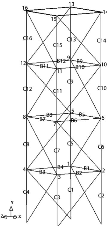
[image:3.595.363.542.330.709.2]Figure37.1shows the frame structure used for the case study. It is a four story steel frame, 150 cm in height and 37.5 cm in length and width. All the columns are steel pipes, 21.1 mm in diameter with 1.8 mm wall thickness. The beams are steel pipes, 15 mm in diameter with 1 mm wall thickness. The diagonal braces are solid bars 3 mm in diameter. The Young’s modulus is 2.1E + 11 N/m2and the density is 7,850 kg/m3. The last story of the frame is a 40402.5 cm steel plate to represent the deck. The frame structure has 16 joints and 4 supports. Since supports are fixed in all degrees of freedom, they are not considered as active nodes and their DOFs are not included in mode shapes. So considering each joint as one node, the structure has 16 nodes. As only the translational DOFs at each node are of interest, the structure has 48 degrees of freedom. DOFs 1–16 are translation of nodes 1–16 along X axis. DOFs 17–32 are translations of the same nodes along Y axis and DOFs 33–48 are their translation along Z axis.
37.4
Finite Element Analysis
Finite element modeling and eigen analysis of the frame structure is performed in Diana 9.2 to determine natural frequencies and mass normalized mode shapes. The first six modes are used to calculate the flexibility matrix. Mode 1 and 2 are the first bending modes along X and Z axis. Mode 3 is the first rotational mode about Y axis. Modes 4 and 5 are the second bending modes along X and Z and mode 6 is the second rotational mode about Y axis.
Six damage scenarios were examined in this study. Three columns and three beams were damaged in their middle. In finite element model, the damage was induced by reducing the Young Modulus of a 5 mm element in the middle of the member. Natural frequencies and mode shapes of the structure were computed for intact and all damage cases. Table37.1
presents the computed natural frequencies for all damage scenarios and for 50% damage severity. It clearly shows the insensitivity of natural frequency to damage, especially in beams.
The damage indicator is the difference of the diagonals of damaged and intact flexibility matrices that are calculated using (37.5). The result is a vector with 48 entries that represent 48 DOFs of the structure. The first, second and third 16 entries of the vector are the flexibility changes of the nodes along X, Y and Z axes respectively.
37.5
Analysis of Damage Indicators
As mentioned earlier, the contribution of members in flexibility matrix are not so straightforward. So unlike beams and slabs, change in flexibility of a member is reflected not in one but in a set of DOFs in the damage indicator. As a result, this indicator does not point on the damage member right away. Instead, the shape of damage indicator needs to be interpreted to estimate the location of damage. It should be mentioned that although locating damage using flexibility changes is the main goal of this study, but it is not particularly the objective of this paper. In this paper, the main concern is to analyze and interpret the trend of the damage indicator when the damaged member is known. The findings of this study and similar studies on different type of frame structures, different type of damages and so on can then be used to come up with a reliable damage detection and localization strategy.
37.5.1
Damage in Columns
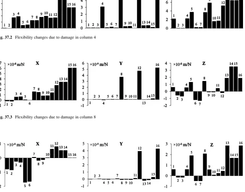
[image:4.595.87.508.69.173.2]Figure37.2 presents the flexibility changes due to damage in column 4 along X, Y and Z axes. The diagram shows a significant rise in the flexibility of nodes 4, 8, 12 and 16 in Y direction. Referring to Fig.37.1, these four nodes are all above the damaged column, suggesting that change in the stiffness of a column alter the flexibility of all nodes above it vertically. Although diagram Y is the main indicator here, but damage in column 4 can also be tracked in two other diagrams. Change in the stiffness of column 4 directly affects the flexibility of node 4 in X and Z directions. Node 3 is connected to node 4 along X axis through beam 3. So its flexibility is influenced by node 4 at X direction. As presented in diagram X, the flexibility of nodes 1 and 2 are not changed and nodes 3 and 4 are raised. For the same reason, the flexibility of nodes 2 and 3 are not changed and nodes 1 and 4 are raised in diagram Z.
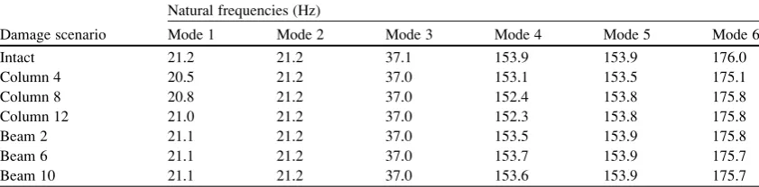
Table 37.1 Natural frequencies of the first six modes for different damage cases
Damage scenario
Natural frequencies (Hz)
Mode 1 Mode 2 Mode 3 Mode 4 Mode 5 Mode 6
Intact 21.2 21.2 37.1 153.9 153.9 176.0
Column 4 20.5 21.2 37.0 153.1 153.5 175.1
Column 8 20.8 21.2 37.0 152.4 153.8 175.8
Column 12 21.0 21.2 37.0 152.3 153.8 175.8
Beam 2 21.1 21.2 37.0 153.5 153.9 175.8
Beam 6 21.1 21.2 37.0 153.7 153.9 175.7
Another observation is that in diagrams X and Z, the flexibility of one node influences the flexibility of nodes above it. For example the flexibility of nodes 5, 9 and 13 in Z direction are raised because of node 1 and the flexibility of nodes 8, 12 and 16 because of node 4. In this regard, the difference between diagram X and Z is due to the bracings’ directions which are opposite along X and Z axes.
Figure37.3presents the flexibility changes due to damage in column 8. The diagram shows a significant rise in flexibility of nodes 8, 12 and 16 in Y direction while the flexibility of node 4 is not changed. This indicates that the location of damage is below node 8 and certainly above node 4 which is somewhere at column 8.
Change of flexibility due to damage in column 12 is shown in Fig. 37.4. As is expected, the damage member raises the flexibility of nodes 12 and 16 in Y direction and did not alter the flexibility of nodes 4 and 8. Based on these three damage scenarios, it is safe to conclude that damage in a column can be accurately located using flexibility based damage indicator.
[image:5.595.58.547.93.477.2]However it is possible to explain the shape of X and Z diagrams when the damage member is known, it is hardly possible to locate the damage column just using X or Z diagram. It is because unlike the flexibility of nodes in Y direction, the damage column alters the X and Z flexibility of the nodes above and below itself. Therefore all can be understood from these diagrams is that the damage member is a column, but the location cannot be estimated. The main reason why diagram Y is a good indicator is that the damage member only alters the flexibility of nodes above it in Y direction.
Fig. 37.2 Flexibility changes due to damage in column 4
Fig. 37.4 Flexibility changes due to damage in column 12
37.5.2
Damage in Beams
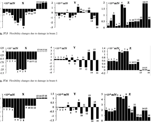
Damage in a beam reduces its axial and shear stiffness at the damaged point. The drop of axial stiffness increases the flexibility of nodes at two ends and at the direction along the beam while the drop of shear stiffness increases the flexibility of those nodes at the other horizontal directions with a much smaller factor. Figure37.5presents change of flexibility due to damage in beam 2. This beam is along Z axis and connected to nodes 2 and 3. So it is expected that damage in beam 2 raise the flexibility of these two nodes along Z axis. Diagram Z is indicating the expected rise in flexibility of nodes 2 and 3, although with different magnitudes. Referring to Fig.37.1, it is because of the diagonal members that are making node 2 stiffer than node 3 in Z direction. Change of flexibility reflects the higher nodes and so nodes 6, 7, 14 and 15 are showing rises in their flexibility along Z. But for some reason nodes 10 and 11 are not backing up this principle. The other two diagrams are not offering any logical pattern that can relate them to the damage member.
Figures37.6and37.7are presenting the flexibility changes due to damage in beams 6 and 10 respectively. These two set of diagrams are surprisingly illustrating the same pattern of flexibility shifts for two different damage scenarios and there is no logical relation between the damaged members and their respective diagrams. It explains that as much as this method is useful and precise to locate damaged columns, it is not so effective to detect damaged beams, at least not in this form.
[image:6.595.57.545.56.458.2]It is possible that the diagonal braces are responsible for the meaningless indicators when it comes to damaged beams. In this frame structure, braces are connecting nodes in a way that adds lots of complexity to the connection of DOFs and their
Fig. 37.5 Flexibility changes due to damage in beam 2
Fig. 37.7 Flexibility changes due to damage in beam 10
effect on each other. In case of columns, since their axial stiffness is much higher than braces, they cannot interfere much. Furthermore columns are all in one line along Y axis and their main indicator is also in Y direction. So the worse braces can do is to influence the magnitude of the flexibility changes, but they do not change the pattern.
To realize whether the diagonal braces are responsible for the problem, the same groups of analyses are performed for the same frame structure, but this time without the diagonal braces. Figure37.8is showing change of flexibility due to damage in beam 2. As explained before, damage in beam 2 causes a rise in the flexibility of nodes 2 and 3 and consequently the nodes above them in Z direction as shown in diagram Z.
A very important concern here is that the shape of diagram Z could also be due to damage in a column. To understand whether the damaged member is a beam or a column, we should analyze two other diagrams. If the damage member is a column, diagram X should also have the same shape as diagram Z, but for different nodes. But here diagram X is presenting uniform change of flexibility in X direction for the nodes at each level. More importantly, if the damage member is a column, diagram Y must show one significant rise at one node of each level. While here it is indicating drops at nodes 2 and 3 and other nodes above it. These all reveal that the damaged member is beam 2.
[image:7.595.65.546.58.486.2]The same concept applies to the damage of beams 6 and 10. Figures37.9and37.10are showing their damage indicators. The diagram Z in both Figures is indicating a rise at the nodes connected to the damaged beams as well as all the nodes above them. This clearly proves that diagonal braces were the reason why the damaged beams could not be located.
[image:7.595.50.546.63.160.2]Fig. 37.10 Flexibility changes due to damage in beam 10 (structure without braces)
Fig. 37.8 Flexibility changes due to damage in beam 2 (structure without braces)
[image:7.595.58.545.374.468.2]37.6
Conclusions and Recommendations
The reliability of using flexibility changes in the frame structures as a damage detection indicator was studied in this paper. This damage detection method is based on determining the changes of flexibility at all DOFs and tries to find a logical relationship between the flexibility changes and the damage member that causes it. In a frame structure, a damage member is directly responsible for the change of flexibility at the nodes connected to it. But it is also indirectly responsible for the change of flexibility at other nodes through other members. So in fact the more complicated the geometry is, the more difficult it is to find a relationship between the damage member and flexibility change diagram. The results were indicating that in a frame structure with diagonal braces, a damaged column can confidentially and accurately be located using this method. This is because of two reasons. First, columns are usually the strongest member in a frame structure and so their damage causes more detectable changes on the flexibility matrix. The second and in fact main reason is their geometry. Columns are connected to each other axially. So damage in a column can only change the flexibility of the nodes above it since the nodes below are connected to the ground through the main axis of lower columns. This makes it very easy to detect and locate damage. In a damaged beam, the major change of flexibility is along its main axis too. But unlike columns, these affected DOFs are connected to the shear axis of the neighboring members. So they influence the flexibility of more nodes and this makes it more difficult to track the damaged member. Based on the results, it is still possible to detect a damaged beam confidently in a frame structure without diagonal braces. But when it comes to frame structures with diagonal members, the geometry’s complexity is so high that it is almost impossible to see any relationship between the damaged beam and the flexibility changes. The only way to overcome this issue is to introduce a factor that somehow decodes the complexity of the geometry and use this factor to filter the damage indicator. This important issue can be the subject of further studies.
References
1. Cornwell P, Doebling SW, Farrar CR (1997) Application of the strain energy damage detection method to plate like structures. In: Proceedings of the 15th international modal analysis conference, Orlando, pp 1312–1318
2. Wang HY, Kimb C (2004) Damage detection in structures using a few frequency response measurements. J Sound Vib 270:1–14 3. Salawu OS (1997) Detection of structural damage through changes in frequency. J Eng Struct 19:718–723
4. Friswell MI, Penny JET, Wilson DAL (1994) Using vibration data and statistical measures to locate damage in structures. Int J Anal Exp Modal Anal 9:239–254
5. Fox C (1992) The location of defects in structures: a comparison of the use of natural frequency and mode shape data. In: Proceedings of the 10th international modal analysis conference, San Diego, CA, 3–7 Feb 1992, Vol. 1 (A94-12476 02-39), pp 522–528
6. Stubbs N, Kim JT, Farrar CR (1995) Field verification of a nondestructive damage localization and severity estimation algorithm. In: Proceedings of the 13th international modal analysis conference IMAC XIII Nashville, Tennessee, USA
7. Yang HZ, Li HJ (2003) Damage localization of offshore platform under ambient excitation. China Ocean Eng 17:307–316 8. Yang HZ, Li HJ (2004) Modal parameter identification of offshore platform under ambient excitation. High Tech Lett 10:80–84
9. Yang H, Li H, James HSL (2004) Damage localization for offshore structures by modal strain energy decomposition method. In: Proceeding of the 2004 American control conference, Boston,30 June–2 July 2004
10. Li H, Wang J, Zhang M, Hu SLJ (2006) Damage detection in offshore jacket structures by cross-model cross-mode method. In: Proceedings of the seventh international conference on hydrodynamics, Naples, pp 171–178
11. Li H, Yang H, Hu SLJ (2006) Strain energy decomposition method for damage localization in 3D frame structures. J Eng Mech ASCE 132:941–951
12. Li H, Fang H, Hu SLJ (2007) Damage localization and severity estimate for three-dimensional frame structures. J Sound Vib 301:481–494 13. Aktan AE, Lee KL, Chuntavan C, Aksel T (1994) Modal testing for structural identification and condition assessment of constructed facilities.
In: Proceedings of the 12th international modal analysis conference, Ilikai Hotel, Honolulu, Hawai, Jan 31–Feb 3, pp 462–468 14. Pandey AK, Biswas M (1994) Damage detection in structures using changes in flexibility. J Sound Vib 169:3–17