http://dx.doi.org/10.4236/ampc.2013.38044
Preparation and Characterization of TiO
2
Photocatalytic
Thin Film and Its Compounds by Micro-Arc Oxidation
Technique
Qun Ma1, Lili Ji2, Yinchang Li1, Tingting Jiang1, Junxia Wang1, Fei Li1, Hongyun Jin1, Yongqian Wang1*
1Engineering Research Center of Nano-Geo Materials of Education China University of Geosciences, Wuhan, China 2Jiangcheng College of China University of Geosciences, Wuhan, China
Email: *cugwyq@126.com
Received October 24, 2013; revised November 25, 2013; accepted December 8, 2013
Copyright © 2013 Qun Ma et al. This is an open access article distributed under the Creative Commons Attribution License, which permits unrestricted use, distribution, and reproduction in any medium, provided the original work is properly cited. In accordance of the Creative Commons Attribution License all Copyrights © 2013 are reserved for SCIRP and the owner of the intellectual property Qun Ma et al. All Copyright © 2013 are guarded by law and by SCIRP as a guardian.
ABSTRACT
Mesoporous TiO2 ceramic films have been prepared upon the Ti alloy substrate by the micro-arc oxidation (MAO)
technology. To enhance the photo-catalytic property of the films, Eu2O3 particles were added into the electrolyte
solu-tion of Na2CO3/Na2SiO3. Scanning electron microscope (SEM), energy dispersive (EDS), X-ray photoelectron
troscopy (XPS) and X-ray diffraction (XRD) are employed to characterize the modified films. Diffuse reflectance spec-tra (DRS) test, photo-generated current test and photo decomposition test are applied to evaluate the photo-catalytic property of the modified films. The results show that Eu2O3 transformed into one-dimensional (1-D) nano-wires
em-bedded within the composite film, and the film has high photo-catalytic property.
Keywords: TiO2; Eu2O3; Compound; Photo-Catalytic Property
1. Introduction
Rice Titanium dioxide (TiO2) is one of the most
impor-tant semi-conductor materials, which is widely used as an efficient photo-catalyst. In terms of environmental pro-tection and new energy, TiO2 has obtained widespread
concern and research because of its chemical stability, biological compatibility and photo-catalytic ability since the report of photolysis of water on titanium dioxide (TiO2) by Fujishima in 1972 [1]. However, the
applica-tion of TiO2 is limited. For the photo-catalytic
applica-tions, the band gap energy (Eg) of the semiconductor is critical. Because of the wideness (3.2 eV) of the Eg of TiO2, and the ultra-violet (UV) light absorption and weak
absorption of visible light [2], considerable efforts have been directed to extend the absorption edge of TiO2
to-ward the visible part of the spectrum in the last three decades. So many researchers have been concentrating on finding an apt process and a modification technology to improve the photo-catalytic property of the TiO2.
TiO2 powder and TiO2 film are the most common
ex-istence forms of TiO2. However, due to the hard recycle
in polluted water and limited depth of photo-radiation, TiO2 powder is not widely used, and thus many
re-searches have been focusing on the preparation of TiO2
film recent years [3-5]. It is well-known that there are many different methods for preparing TiO2 film, such as
sol-gel [6-9], liquid phase deposition (LPD) [10], hy-drolysis precipitation [11] and chemical vapor deposition [12,13], etc. TiO2 film can also be produced via
mi-cro-arc oxidation (MAO) technology [14,15]. Generally speaking, MAO is a useful approach for forming a ce-ramic coating on the surface of valuable metals, such as Al, Mg and Ti, and their alloys [16]. MAO is a process based on the anodic oxidation and occurs at potentials above the breakdown voltage of the oxide layer formed on the anode surface [17]. Now, micro-arc oxidation (MAO) is most frequently used to prepare TiO2 film. The
TiO2 film that is prepared through MAO has much high
photo-catalytic activity. To enhance the efficiency of photo-catalytic property of TiO2 film prepared by MAO,
rare earth metals with incompletely occupied 4f and empty 5d orbit also often serve as catalysts or promote catalysis. Besides, it has been proved that metal Eu, as one of the rare earth metals, has the ability to improve the photo-catalytic activity of the TiO2 films, because of
the electrons trap effect supplied by the alterable chemi-cal valence (Eu2+ and Eu3+) sites [20].
In the present work, we have prepared TiO2 film upon
Ti alloy substrate via MAO technology. Meanwhile, in order to get high efficient photo-catalytic property, rare earth metal oxide Eu2O3 was compounded into the TiO2
film, and methyl blue dye was used to test the photo- catalytic efficiency under UV-Vis irradiation. The grain could be combined on the surface of the TiO2 layer
di-rectly by the MAO process of high temperature and fast solidification, which could improve its photo-catalytic property.
2. Experimental
All chemicals were of analytical grade and used without further purification. In our work, Eu2O3 particles were
added into the electrolyte directly after ultrasonic disper-sion in distilled water. We prepared uniform TiO2/Eu2O3
film upon Ti alloy substrate by using the high tempera-ture and fast solidification of MAO process. Meanwhile, we also prepared pour TiO2 film, so as to make a contrast
with films were produced without adding semiconductor compound into the electrolyte. Follow these steps:
At first, we made up 5 L electrolyte. The electrolyte was a mixed solution of sodium carbonate (20 g/L) and sodium silicate (8 g/L). The anode was TC4 substrate with reaction area of 20 × 20 × 5 mm. After polishing, the substrates were cleaned by ethanol, acetone and dis-tilled water. A stainless steel container was used as elec-trolyte cell and cathode. MAO of titanium alloy substrate was carried out at a constant current using a 60 KW AC power supply. Different current densities were reached by adjusting the voltage between two working electrodes.
The temperature was controlled below 40˚C within a small circulating water channel. Oxidation time was ten minutes. And then, the pure TiO2 film was prepared upon
TC4 substrate when the voltage was 400 V and stable. Last, 10 g Eu2O3 particles were added into the same
elec-trolyte (the concentration of Eu2O3 was 2 g/L). The
TiO2/Eu2O3 composite films were prepared at different
voltage, 300 V, 350 V and 400 V. The detail experimen-tal conditions were listed in Table 1.
The morphologies of the films and their chemical compositions were characterized by using scanning elec-tron microscope (SEM), energy dispersive spectrometer (EDS) and X-ray photoelectron spectroscopy (XPS). The crystal structure was measured by using X-ray diffract meter (XRD) (D8 Advanced, Bruker AXS, Germany) with Cu Ka radiation (the scanning speed is 6˚ per min-ute). Photo-catalytic property was tested by diffuse re-flectance spectra (DRS) test, photo-generated current test, and photo decomposition test.
Diffuse reflectance spectra (DRS) test UV-Vis
dif-fuse reflectance spectra (DRS) of the TiO2 layers were
measured on the diffuse reflectance accessory of UV-Vis recording spectro-photometer (UV-2550, Shimadzu, Ja-pan).
Photo-generated current test The TiO2 layer,
satura-tion calomel electrode and the platinum electrode, which were immersed in 1 mol/L NaOH aqueous solution, were chosen to the working electrode, reference electrode and counter electrode respectively. The working electrode was irradiated by using a high pressure mercury lamp (160 W) in 10 cm horizon distance away. The photocur-rent was detected using an electrochemical workstation (CHI 660C, Chenhua, Shanghai).
Photo decomposition test The methyl blue solution of
12 mg/L was pour into two beakers. The TiO2 layer
[image:2.595.55.540.609.734.2]without complex and the compounded layers were im-mersed in them, and the left was used as reference. All of them were illuminated by a high pressure mercury lamp (160 W) under 15cm vertical distance. The absorbance of methyl blue solution was measured by a UV-Vis spec-trophotometer (UV-2550, Shimadzu, Japan).
Table 1. Experimental conditions of the TiO2/Eu2O3 compounded film.
Electrical Electrolyte
Voltage Samples
Forward Negative
Frequency Duty cycle Time Na2CO3 Na2SiO3·9H2O Eu2O3
TiO2 400 V 10 V 1 KHz 20% 10 min 20 g/L 8 g/L No
TiO2/Eu2O3 300 V 10 V 1 KHz 20% 10 min 20 g/L 8 g/L 2 g/L
TiO2/Eu2O3 350 V 10 V 1 KHz 20% 10 min 20 g/L 8 g/L 2 g/L
TiO2/Eu2O3 400 V 10 V 1 KHz 20% 10 min 20 g/L 8 g/L 2 g/L
3. Results and Discussions
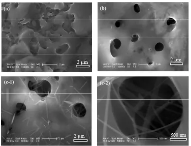
The SEM morphologies of the pure TiO2 film at 400V
are shown in Figure 1. From Figure 1, we can see
clearly that the pure TiO2 film is porous with diameter of
pores (the diameter of pores is about 1 - 5 µm). Figure 2
shows the SEM morphologies of the TiO2/Eu2O3
com-posite films at 300 V, 350 V and 400 V. Meanwhile, Fig-ure 2 gives its two different magnifications photos at 400
V. It can be seen that the MAO TiO2 surface exhibits a
typical crater and porous microstructure with a diameter around 1 - 2 µm. At 300 V and 350 V, the surface of the TiO2/Eu2O3 composite film present micro pore structure,
as shown in (a) and (b), which is just ordinary film pre-
pared by MAO technology. However, at the high voltage 400 V, there are many one-dimensional (1-D) structures homogeneously embedded within the film, as shown in (c-1) and (c-2). Due to the small size effect, these 1-D structures can enhance the photo-catalytic property of TiO2 film. So, our researches were concentrated on the
TiO2/Eu2O3 composite film prepared at 400V. In order to
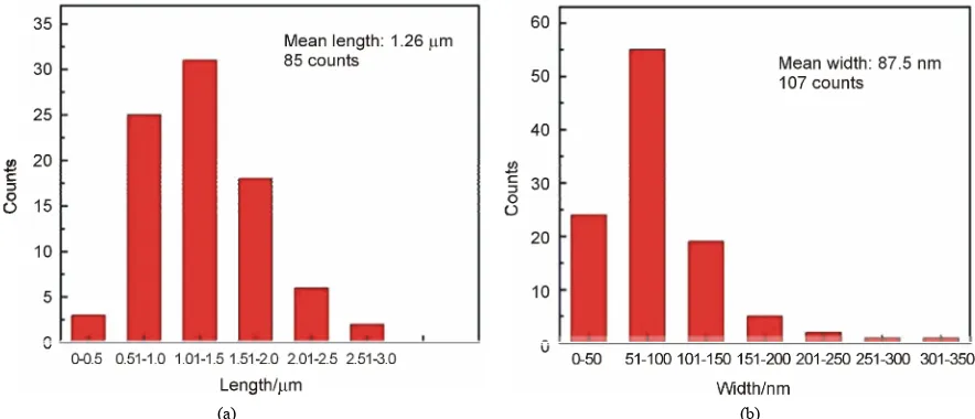
get more detail information about the 1-D nano-wires materials on the surface of TiO2/Eu2O3 film, we made
size statistics about it. It can be noticed that these 1-D nano-wires have the average length of 1.26 μm and the average width of 87.5 nm from Figure 3.
In order to prove that the 1-D nano-wires were Eu2O3,
[image:3.595.85.513.258.398.2]
Figure 1. SEM morphologies of TiO2 film without composites. (a) Low magnification; (b) High magnification.
(a) (b)
2 µm 2 µm
500 nm
(c-1) (c-2)
2 µm
[image:3.595.105.493.423.720.2][image:4.595.76.518.85.275.2]
(a) (b)
Figure 3. Statistical size distribution of the nano-wires on TiO2/Eu2O3 composite film: (a) Length; (b) Width.
which were added into the electrolyte and entered into the micro-porous of the TiO2 films, we made EDS test.
EDS measurement revealed that these 1-D nano-wires were composed of Eu and O elements, as shown in Fig-ure 4, which implies that original Eu2O3 particles have
transformed into 1-D nano-wires during MAO process. At the same time, we know that Ti and some O elements come from the TiO2 film, and Au elements come from
SEM observation of injection of the sample, and Na ele-ments come from the electrolyte.
XPS technique was applied to confirm Eu2O3
exis-tence in the TiO2/Eu2O3 composite film and investigate
the chemical states of the elements, whose result is pre-sented in Figure 5. It can be seen that the peaks mainly
contain the Ti 2p, O 1s, C 1s and Eu 3d5, which also
demonstrates the existence of Eu2O3 inside the film. Figure 6(a) illustrates XRD patterns of the pure TiO2
and the TiO2/Eu2O3 composite film (400V). It can be
noticed clearly that both of them mainly contain anatase phase with few rutile phase. At the same time, we know that 1-D nano-wires have little affection to the crystal structure of the films. Figure 6(b) displays the enlarged
XRD peaks of anatase TiO2 plans A (101) in the 2θ
re-gion of 24.0˚ - 27.0˚. We measured the full width half maximum (FWHM) of the main peak of anatase TiO2
plans (101) in the 25.3˚. The result is that the FWHM of the pure TiO2 film is 0.24 and the TiO2/Eu2O3 composite
film is 0.28. Using the Scherrer Formula, we calculated that in pure TiO2 film, the grain size of anatase TiO2 is
about 33 - 34 nm but in the TiO2/Eu2O3 composite film,
the size is around 28 - 29 nm. From calculation results, we found that the grain size of anatase in the TiO2/Eu2O3
composite film decreased obviously, compared with pure TiO2 film. The reason is that rare earth metals has
in-completely occupied 4f and empty 5d orbit and the growth of TiO2 grains was inhibited after Eu2O3 was
compounded in TiO2 films.
For the sake of studying the photo-catalytic properties of the TiO2/Eu2O3 composite film (400 V), diffuse
re-flectance spectra (DRS) test was employed and its result is presented in Figure 7. Obviously, the composite film
exhibits a higher absorption of UV and visible light with an Einstein shift about 10 nm. Before Eu2O3 was
com-pounded, the pure TiO2 film only has little absorption of
visible light. The results reveal that improved absorption in UV and visible light ranges is contributed from the addictive phase Eu2O3. Eu3+ possesses abundant energy
levels, so Eu2O3 can increase the absorption of UV and
visible light and improve the photo-catalytic properties of the composite film.
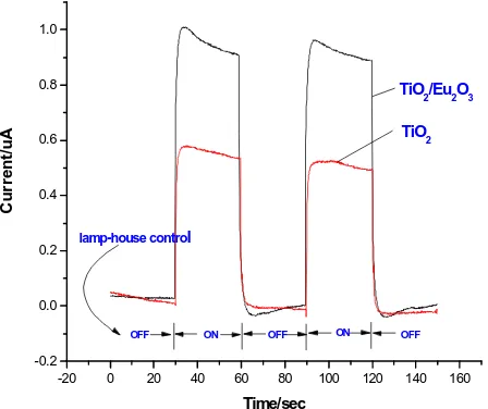
To study the photo-catalytic efficiency of the TiO2/
Eu2O3 composite film (400 V), we also measured the
intensity of photo-generated current of it, as shown in
Figure 8. The reason why the TiO2/Eu2O3 composite
film has a higher intensity of photon generated current is that in Eu2O3, iron Eu3+ has an incomplete 4f orbital track
and an empty 5d orbital track, which tends to produce multi-electron configuration and therefore can effectively inhibit the recombination of photo-electrons and holes.
Figure 9 shows the result of the degradation
experi-ments of methyl blue. It revealed that the photo-catalytic performance of the TiO2/Eu2O3 composite film (400 V)
exhibited two times higher than that of the pure TiO2
film. We can see that after four hours, the degradation of methyl blue reaches to 90% when using the TiO2/Eu2O3
composite film (400 V), while only 45% when using the film without Eu2O3.
4. Conclusion
In conclusion, the TiO2 films were prepared upon Ti
films had a porous structure with a rough surface which is suitable for modification. When rare earth metal oxide Eu2O3 was added into the electrolyte, a composite film
was produced during MAO and Eu2O3 transformed into
one-dimensional (1-D) nano-wires embedded within the
composite film. Comparing with the pure films, the composite films exhibited high efficient photo-catalytic properties, such as high absorption in UV and visible light ranges, high photo-generated current intensity and high photo degradation rate.
[image:5.595.61.536.298.717.2]
(a) (b)
Figure 4. EDS analysis of the TiO2/Eu2O3 composite film.
0.00E+00 1.00E+05 2.00E+05 3.00E+05 4.00E+05 5.00E+05 6.00E+05 0 200 400 600 800 1000 C ounts / s
Binding Energy (eV) Survey Al 300W PE 100eV
0.00E+00 1.00E+04 2.00E+04 3.00E+04 4.00E+04 5.00E+04 6.00E+04 450 452 454 456 458 460 462 464 466 468 C oun ts / s
Binding Energy (eV) Ti 2p Al 300W PE 25eV
Ti2p 0.00E+00 1.00E+05 2.00E+05 3.00E+05 4.00E+05 5.00E+05 6.00E+05 0 200 400 600 800 1000 C ounts / s
Binding Energy (eV) Survey Al 300W PE 100eV
0.00E+00 1.00E+04 2.00E+04 3.00E+04 4.00E+04 5.00E+04 6.00E+04 450 452 454 456 458 460 462 464 466 468 C oun ts / s
Binding Energy (eV) Ti 2p Al 300W PE 25eV
Ti2p 450 Count s/s Count s/s
(a) (b)
0 7.40E+04 7.60E+04 7.80E+04 8.00E+04 8.20E+04 8.40E+04 1130 1140 1150 1160 C ounts / s
Binding Energy (eV) Eu 3d Al 300W PE 25eV
Eu3d5 0 7.40E+04 7.60E+04 7.80E+04 8.00E+04 8.20E+04 8.40E+04 1130 1140 1150 1160 C ounts / s
Binding Energy (eV) Eu 3d Al 300W PE 25eV
Eu3d5
Count
s/s
(c)
[image:6.595.135.459.80.262.2]
(a) (b)
Figure 6. XRD patterns of the TiO2 and the TiO2/Eu2O3 composite films prepared by MAO (a)survey, (b) anatase (101) peak.
200 300 400 500 600 700 800
0.3 0.4 0.5 0.6 0.7 0.8 0.9 1.0 1.1 1.2 1.3
Ab
s
./
a
.u
.
wavelength/nm
TiO2/Eu2O3
TiO2
Einstein shift
1.3
1.2
1.1
1.0
0.9
0.8
0.7
0.6
0.5
0.4
0.3
[image:6.595.61.286.292.481.2]200 300 400 500 600 700 800
Figure 7. UV-Vis spectra of the TiO2 film and the TiO2/ Eu2O3 composite film.
-20 0 20 40 60 80 100 120 140 160
-0.2 0.0 0.2 0.4 0.6 0.8 1.0
ON
OFF OFF
Cu
rr
e
n
t/u
A
Time/sec
TiO2/Eu2O3
TiO2
OFF ON
lamp-house control
Figure 8. Photo-generated current of pure TiO2 and TiO2/ Eu2O3 composite film.
TiO2/Eu2O3 (400 V)
TiO2
100
80
60
40
20
0
Ab
s/
a.u.
0 50 100 150 200 250 300 Time/min
Figure 9. The concentration of methylene blue photo-de- graded by pure TiO2 and TiO2/Eu2O3 film.
5. Acknowledgement
The work was supported by the National Natural Science Foundation of China (21203170, 21201156), the Hall of Hubei Province Science and Technology Project (2011CDB347) and the Fundamental Research Funds for the Central Universities, China University of Geosci- ences (Wuhan, CUG130401), National Training Pro-grams of Innovation and Entrepreneurship for Under-graduates (201310491015). The financial support was gratefully appreciated.
REFERENCES
[1] A. Fujishima and K. Honda, “Electrochemical Photocata-lysis of Water at a Semiconductor Electrode,” Nature, Vol. 238, 1972, pp. 37-38.
http://dx.doi.org/10.1038/238037a0
[image:6.595.314.533.299.445.2] [image:6.595.61.285.519.707.2]http://dx.doi.org/10.1016/0022-0728(84)80059-5 [3] Y. Han, D. H. Chen and L. Zhang, “Nano-Crystallized
SrHA/SrHA-SrTiO3/SrTiO3-TiO2 Multilayer Coatings For-
med by Micro-Arc Oxidation for Photo-Catalytic Appli-cation,” Nanotechnology, Vol. 33, No. 19, 2008, Artivle ID: 335705.
[4] F. D. Fonzo, C. S. Casari, V. Russo, M. F. Brumella and A. L. Bassi, Nanotechnology, Vol. 20, 2009, pp. 15604- 15610.
http://dx.doi.org/10.1088/0957-4484/20/1/015604 [5] L. Wan, J. F. Li, J. Y. Feng, W. Sun and Z. Q. Mao,
“Photo-Catalysts of Cr Doped TiO2 Film Prepared by
Micro Arc Oxidation,” Chinese Journal of Chemical Phy- sics, Vol. 5, No. 21, 2008, pp. 487-492.
http://dx.doi.org/10.1088/1674-0068/21/05/487-492 [6] D. Chatterjee and S. Dasgupta, “Visible Light Induced
Photocatalytic Degradation of Organic Pollutants,” Pho-tochemistry and Photobiology, Vol. 2-3, No. 6, 2005, pp. 186-205.
[7] V. Ramaswamy, N. B. Jagtap, S. Vijayanand, D. S. Bhange and P. S. Awati, “Photocatalytic Decomposition of Methylene Blue on Nano-Crystalline Titania Prepared by Different Methods,” Materials Research Bulletin, Vol. 5, No. 43, 2008, pp. 1145-1152.
http://dx.doi.org/10.1016/j.materresbull.2007.06.00 3
[8] A. Z. Moshfegh, “Nano-Particle Catalysts,” Journal of Physics D-Applied Physics, Vol. 23, No. 42, 2009, Article ID: 233001.
http://dx.doi.org/10.1088/0022-3727/42/23/233001 [9] M. Janus, E. Kusiak and A. W. Morawski, “Carbon
Modified TiO2 Photo-Catalyst with Enhanced Adsorptiv-ity for Dyes from Water,” Catalysis Letters, Vol. 3-4, No. 131, 2009, pp. 506-511.
http://dx.doi.org/10.1007/s10562-009-9932-z [10] H. T. Feng, F. Wang and X. G. Tong, “LPD Preparation
of Iron-Doped TiO2 Films and Its Performance Analy-sis,” Ceramics international, Vol. 2, 2006, pp. 16-17. [11] L.Y. Shi, H. C. Gu and C. Z. Li, “Preparation and
Proper-ties of SnO2-TiO2 Composite Photo-Catalysts,” Chinese Journal Catalysis, Vol. 20, 1999, pp. 338-342.
[12] P. Evans, T. English, D. Hammond, M. E. Pemble and D. W. Sheel, “The Role of SiO2 Barrier Layers in
Determin-ing the Structure and Photo-Catalytic Activity of TiO2
Films Deposited on Stainless Steelv,” Applied Catalysis, Vol. 2, No. 321, 2007, pp. 140-146.
[13] J. Mungkalasiri, L. Bedel, F. Emieux, J. Doré, F. N. R. Renaud and F. Maury, “DLI-CVD of TiO2-Cu
Antibacte-rial Thin Films: Growth and Characterization,” Surface and Coatings Technology, Vol. 6-7, No. 204, 2009, pp. 887-892.
http://dx.doi.org/10.1016/j.surfcoat.2009.07.015 [14] E. Matykina, A. Berkani, P. Skeldon and G. E. Thompson,
“Real-Time Imaging of Coating Growth during Plasma Electrolytic Oxidation of Titanium,” Electrochimica Acta, Vol. 4, No. 53, 2007, pp. 1987-1994.
http://dx.doi.org/10.1016/j.electacta.2007.08.074 [15] F. Chen, H. Zhou, C. Chen and Y. J. Xia, “Study on the
tri-Biological Performance of Ceramic Coatings on Tita-nium Alloy Surfaces Obtained through Micro-Arc Oxida-tion,” Progress in Organic Coatings, Vol. 2-3, No. 64, 2009, pp. 264-267.
[16] W. Xue, Z. Deng, Y. Lai and R. Chen, “Analysis of Phase Distribution for Ceramic Coatings Formed by Micro-Arc Oxidation on Aluminum Alloy,” Journal of the American Ceramic Society, Vol. 5, No. 81, 1998, pp. 1365-1368. [17] S. Ikonopisov, “Theory of Electrical Breakdown during
Formation of Barrier Anodic Film,” Electrochemical Acta, Vol. 22, 1977, pp. 1077-1082.
http://dx.doi.org/10.1016/0013-4686(77)80042-X [18] N. Schiffa, B. Grosgogeata, M. Lissaca and F. Dalardb,
“Influence of Fluoride Content and pH on the Corrosion Resistance of Titanium and Its Alloys,” Biomaterials, Vol. 9, No. 23, 2002, pp. 1995-2002.
http://dx.doi.org/10.1016/S0142-9612(01)00328-3 [19] Y. K. Lee, “Effects of Electrical Parameters on Titania
Film Grown by Micro Arc Oxidation,” Modern Physics Letters B, Vol. 16, No. 23, 2009, pp. 2035-2040.
http://dx.doi.org/10.1142/S0217984909020072 [20] P. Yang, C. Lu and N. Hua, “Titanium Dioxide Nano-
Particles Co-Doped with Fe3+ and Eu3+ Ions for Photo-
Catalysis,” Materials Letters, Vol. 57, 2002, pp. 794-801.