http://dx.doi.org/10.4236/jsea.2013.612075
Intelligent Agent Based Mapping of Software Requirement
Specification to Design Model
Emdad Khan, Mohammed Alawairdhi
College of Computer and Information Sciences, Al-Imam Muhammad Ibn Saud Islamic University, Riyadh, KSA. Email: [email protected], [email protected]
Received September 23rd, 2013; revised October 20th, 2013; accepted October 28th, 2013
Copyright © 2013 Emdad Khan et al. This is an open access article distributed under the Creative Commons Attribution License, which permits unrestricted use, distribution, and reproduction in any medium, provided the original work is properly cited. In accor- dance of the Creative Commons Attribution License all Copyrights © 2013 are reserved for SCIRP and the owner of the intellectual property Emdad Khan et al. All Copyright © 2013 are guarded by law and by SCIRP as a guardian.
ABSTRACT
Automatically mapping a requirement specification to design model in Software Engineering is an open complex prob- lem. Existing methods use a complex manual process that use the knowledge from the requirement specifica- tion/modeling and the design, and try to find a good match between them. The key task done by designers is to convert a natural language based requirement specification (or corresponding UML based representation) into a predominantly computer language based design model—thus the process is very complex as there is a very large gap between our natural language and computer language. Moreover, this is not just a simple language conversion, but rather a complex knowledge conversion that can lead to meaningful design implementation. In this paper, we describe an automated method to map Requirement Model to Design Model and thus automate/partially automate the Structured Design (SD) process. We believe, this is the first logical step in mapping a more complex requirement specification to design model. We call it IRTDM (Intelligent Agent based requirement model to design model mapping). The main theme of IRTDM is to use some AI (Artificial Intelligence) based algorithms, semantic representation using Ontology or Predicate Logic, design structures using some well known design framework and Machine Learning algorithms for learning over time. Semantics help convert natural language based requirement specification (and associated UML representation) into high level design model followed by mapping to design structures. AI method can also be used to convert high level design structures into lower level design which then can be refined further by some manual and/or semi automated process. We emphasize that automation is one of the key ways to minimize the software cost, and is very important for all, especially, for the “Design for the Bottom 90% People” or BOP (Base of the Pyramid People).
Keywords: Software Engineering; Artificial Intelligence; Ontology; Intelligent Agent; Requirements Specification;
Requirements Modeling; Design Modeling; Semantics; Natural Language Understanding; Machine Learning; Universal Modeling Language (UML); ICT (Information and Communication Technology and BOP (Base of the Pyramid People)
1. Introduction
Converting requirement specification or model to design model followed by an implementation is an important part of software engineering, especially for a large scale software. It is both information conversion and know- ledge conversion, and it involves both art and science. Hence the process is complex. In fact, the various levels of abstractions involved in such mapping (e.g. from requirement model to design model, to architecture, to implementation) make the process even more complex. Designers use their expertise and various available tools
population. This fits well, with “Design for the bottom 90% people”. Automation is one of the key ways to minimize the software cost [1].
Many researchers have been working on automating various parts of the software engineering including soft- ware development process. e.g. to help architectural design, and various models have been proposed like Structural Models, Framework Models, Dynamic Models, Process Models and Functional Models ([2-5]). A number of different Architectural Description Languages (ADLs) have been developed to represent these models ([6,7]). Similarly, to help requirement modeling, various languages have been developed e.g. Requirement Model- ing Language, RML ([8,9]). However, we could not find any citation regarding automatically mapping a Require- ment Model to a Design Model. A few somewhat related researches are covered in ([10,11]).
In this paper, we present an Intelligent Agent (IA) based automated method to map Requirement Model to a Design Model. It is called IRTDM (Intelligent Agent based requirement model to design model mapping). The IA uses Artificial Intelligence (AI), semantic represen- tation using Ontology or Predicate Logic, Design Struc- tures (DS) using some well known design framework and Machine Learning algorithms for learning over time. We specifically focus on mapping Requirement Model to Architecture. Mapping to other key software areas/steps (e.g. converting the architecture into operational software) is also possible using similar approach but not covered in this paper.
Section 2 provides a brief high level overview of IRTDM (Intelligent Agent based requirement model to design model mapping). Section 3 describes the basics of the Flow-Oriented Requirement modeling to Data-Flow architecture mapping method as done by experienced designers. Section 4 describes an automated version of Section 3 using Natural Language Processing/Under- standing, Artificial Intelligence and an Intelligent Agent. Section 5 describes the Architecture and Algorithms for more general and versatile Intelligent Agent. It also briefly discusses how to apply the concept for other types of mapping, Section 6 describes future work and Section 7 provides conclusions.
2. High Level Overview of IRTDM
There is a good correspondence between requirement model and design model (Figure 1). Various parts of the Requirement Model have corresponding mapped parts in the design model. E.g. class-based elements map to data/ class, architecture and component design parts in the design model. In fact, designers use such basic mapping as a basis to come up with an architecture. Designers also use various levels of architectural abstractions (e.g. Ar-
chitectural Genre, Architectural Styles, Archetypes) to come up with the structure showing key blocks or com- ponents. Our main theme is to use designers approach to come up with an automated approach. It is important to note that for some cases there is no practical mapping from requirement model to some architectural styles. But for many cases such mapping exists. A good example is mapping Flow-Oriented Requirement modeling to Data- Flow architecture style. Since enough abstractions al- ready exist and the manual method is understood rea- sonably well, we can convert the same into appropriate steps that can be done by an Intelligent Agent (IA) i.e. IA in IRTDM. First we discuss a simple IA to automati- cally handle Flow-Oriented Requirement modeling to Data-Flow architecture. Then we discuss more general IA.
The key issues a general IA needs to address are: 1) Use of proper rules in doing the mapping. 2) Use of semantics to ensure correct mapping. 3) Use of appropriate rules and semantics to help map/ transform one architectural style to another (e.g. Data- flow architecture to Layered architecture).
4) Use of Learning to improve the outcome. 5) Use of Verification to ensure correctness.
6) Help Ensure that Implementation (coding) can also be automated in a similar way.
7) Other key issues as appropriate (e.g. refactoring, generating test vectors and performing basic tests).
3. Flow-Oriented Requirement Modeling to
Data-Flow Architecture Mapping
A mapping technique called Structured Design (SD) is often characterized as a data flow-oriented design me- thod [10] as it provides a convenient transition from a data flow diagram (DFD) to software architecture. Such transformation involves the following 6 steps:
a) The type of data (information) flow is established. b) Flow boundaries are determined.
c) The DFD is mapped into the program structure. d) Control hierarchy is defined.
e) Resultant structure is refined using design measures and heuristics, and
f) The architectural description is refined and elabora- ted.
In order to design optimal module structure and inter- faces two principles are crucial [12]:
Cohesion which is “concerned with the grouping of functionally related processes into a particular mo- dule” and
Analy sis Model
use-cases - text use-case diagrams activity diagrams swim lane diagrams
data flow diagrams control-flow diagrams processing narratives
f l o w- o r i e n t e d e l e m e n t s
b e h a v i o r a l e l e m e n t s c l a ss- b a se d
e l e m e n t s sc e n a r i o - b a se d
e l e m e n t s
class diagrams analysis packages CRC models collaboration diagrams
state diagrams sequence diagrams
D a t a / Cl a ss D e si g n A r c h i t e c t u r a l D e si g n
I n t e r f a c e D e sig n
Co m p o n e n t - L e v e l D e si g n
[image:3.595.62.534.84.385.2]Design Model
Figure 1. Flow-Oriented Requirement Modeling to Data-Flow Architecture Mapping (Courtesy [12]).
[Note: In general, Structured Design (SD) and
Structured Analysis (SA) are methods for analyzing and converting business requirements into specifi- cations and ultimately, computer programs, hard- ware configurations and related manual procedures. SA includes Context Diagram, Data Dictionary, DFD, Structure Chart, Structured Design and Struc- tured Query Language (SQL)].
One form of information mapping is called Trans-
form mapping where incoming data is transformed into
an internal form by a transform center. The transformed data then flows to external world using outgoing flow. Another form of information mapping is called Transac-
tion mapping in which a single data item triggers one or
a number of information flows that effect a function im- plied by the triggering data item. The data item is called a transaction.
The above mentioned steps are done by designers (all types of designers including database and data warehouse designers and system architects) using the Requirement Model (in this case the Flow-oriented model) and the designstructures including Design Genre, Design Styles (in this case data flow architecture), set of archetypes (e.g. Controller, Detector, Indicators, Node), basic classes (some of which are described in the Requirement Model) and some basic design guidelines. Refer to “Software
Engineering: A Practitioner’s Approach” by Roger Press- man [12] for a detailed example. We basically automate these steps using NLU, AI and an Intelligent Agent as described below in Sections 4 and 5.
4. Automating Flow-Oriented Requirement
Modeling to Data-Flow Architecture
Mapping
Converting Flow-Oriented Requirement Modeling to Data-Flow Architecture is a good start because of its simplicity. In this case there is a direct correspondence between the requirement modeling steps and architec- tural mapping steps as both use the same DFD.
4.1. Basic Ideas
Use the requirement modeling flow information and match it using AI rules to the corresponding Data-Flow Architecture. Since there is 1-1 correspondence (refer to
Figure 1), Flow-Oriented elements have 1-1 correspon-
Referring to Figure 1, there is a 1-1 correspondence from the DFD Requirement Model to Architectural De- sign, Interface Design and Component Level Design. Thus, we need appropriate rules to map to all such design levels. Cohesion and coupling are appropriately used to ensure optimal design module structures and interfaces. Any standard automatic/semi-automatic technique can be used to determine the optimal design module structures and interfaces. All these key steps can be iterated during the refinement process (steps #e and #f in Section 3).
4.2. Requirement Modeling and Natural Language Processing (NLP)
Requirement Modeling methods usually use natural lan- guage words or equivalent methods. For example, in a Use Case diagram, the concept is expressed using natural language type concept. Class based, Behavioral based and DFD approaches also use natural language type concept. Thus, it is important to use Natural Language semantics and Natural Language Processing (NLP) in automating the mapping of Requirement Modeling to Design process. In case of DFD based modeling (as al- ready mentioned), we would need semantics and NLP to map DFD to the program structure, determine control hierarchy, complete refinement and elaboration.
Besides, in a typical design,
a) The software must be placed into context i.e. the design should define the external entities (other systems, devices, people) that the software interacts with and the nature of the interaction.
b) A set of architectural archetypes should be identi- fied—an archetype is an abstraction (similar to a class) that represents one element of system behavior.
c) The designer specifies the structure of the system by defining and refining software components that imple- ment each archetype.
NLP becomes handy in automating all these activities. Let’s use an example to demonstrate the use of semantics and NLP:
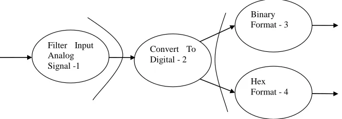
Refer to Figure 2—it shows a simple DFD with rea- sonable details (i.e. say level 3 DFD). An analog signal is input to an Analog to Digital conversion unit (the Trans- form center circle or bubble #2) after doing some filter- ing operation by circle #1. The transform center outputs the digital signal in two format—binary (bubble #3) and hexadecimal (bubble #4). All bubbles are labeled with words that are easily understandable to human being as these are natural language words. Our goal is to use the semantic meaning of these words to come up with a de- sign structure as designers usually do.
Consider the words “Analog to Digital Conversion” in bubble #2. The semantic meaning of this is “Conversion from an analog signal to digital signal takes place here” (see Section 4.3 below how such semantics is derived/ programmed). Once the program knows this semantics, it can determine the corresponding design archetypes and top level design box using AI rules which are based on the domain knowledge, semantics, and the DFD itself.
Figure 3 shows the corresponding design structure. Such
as structure is achieved using the following concept (the corresponding rules are given in Section 4.3):
1) The boundaries shown in Figure 2 are used to focus on the design of bubble #2. This is as per standard DFD based design process as outlined in Section 3.
2) Such boundaries can easily be done by representing the DFD using a Graph which can be implemented using netlist.
3) Since bubble #2 is taking one input and producing 2 outputs of different data formats, bubble #2 is doing a “Transform flow”.
4) The outputs of the transform flow are detailed out in the DFD itself. So, corresponding design blocks can eas- ily be constructed (Figure 3 shows this using DFD
based mapping to a Call and Return architecture).
5) As bubble #2 is doing a transform operation, it needs to do a “control function” in addition to do the main “transform function”. This again is part of the standard design process that de signers use in a Struc- tured Design.
Convert To Digital - 2 Filter Input
Analog Signal -1
Binary Format - 3
[image:4.595.133.467.579.696.2]Hex Format - 4
Analog To Digital Converter Executive
Input Signal Controller
Analog to Digital Converter
Output Signal Controller
Binary Format
[image:5.595.154.439.88.211.2]Hex Format A2D
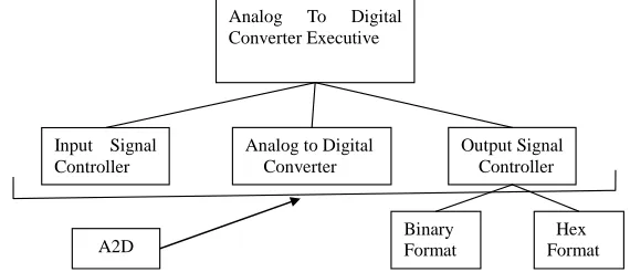
Figure 3. Design structure constructed by using the DFD in Figure 2. Semantics of the bubbles 2, 3 and 4 in Figure 2 and corresponding rules are used to make the construction. Semantics and all associated rules are implemented using First Order Logic (FOL). See Section 4.2 and Section 4.3 for details.
6) Netlist of the DFD is used to move and identify the new boundaries (by the automation software i.e. IA), find the new transform center and complete the design for new transform center, e.g. Binary Format-3 bubble and Hex Format bubble (Figure 3).
The following Section implements these concepts us- ing semantics, NLP and AI. And all these are part of the Intelligent Agent, IA.
4.3. Predicate Calculus and Mapping Rules
The rules mentioned above can be represented by Predi- cate Calculus rules. Predicate Calculus can also be used to define semantics. We can also use Ontology to define semantics. In this paper, we are using Predicate Calculus to describe the rules and semantics.
Consider the words “Analog to Digital Conversion” in bubble #2 in Figure 2 (as described in Section 4.2). The semantic meaning of this is “Conversion from an analog signal to digital signal takes place here” or simply “Con- version from an analog signal to digital”. In predicate calculus (or First order logic, FOL), we can use the fol- lowing to represent this semantics:
Converts (Convert to Digital-2, AnalogToDigital) …(1) AnalogToDigitalConverter (Convert to Digital-2) …(2) Converts (AnalogToDigitalConverter, AnalogToDigi- tal) …….………..………(2a)
When “Convert to Digital-2” label is seen in DFD bubble #2, the semantics determines that this is an analog to digital converter. Hence, all the design structures have the key blocks needed to implement the function of an analog to digital converter (Figure 3).
To make it more general, we use universal quantifier “for all” i.e. ∀ to say,
“All analog to digital converters convert analog signal to digital signal” ………..………(3a)
Which can be written in FOL
∀x AnalogtoDigitalConverter (x) ⇒ Converts (x, AnalogToDigital) ……….….…….….(3b)
Using the universal quantifier, we allow to use any
analog to digital converter in our knowledgebase or li- brary.
[Note: mathematically, x can be any variable, in- cluding an instance of a non-AnalogToDigitalCon- verter [13]. This, however, can be avoided in vari- ous ways. We take care of this by only allowing analog to digital converters in the corresponding li- brary].
In addition, an Executive control block (Analog To Digital Converter Executive) and a few other associated control blocks (e.g. input signal controller and output signal controller) are generated (Figure 3) as per stan- dard design technique used in DFD model. Similarly, using the semantics of other bubbles, blocks to handle the binary and hex format are constructed. The FOL rules are used to describe all these as shown below:
If x is AnalogToDigitalConverter then Blocks are “Analog To Digital Converter Executive” AND “Analog To Digital Converter” AND “Input Signal Controller”
AND “Output Signal Controller” ………..…...(4) If x is Binary Format then Blocks are “Binary For- mat” ………...……….….….(5)
If x is Hex Format then Blocks are “Hex For- mat” ...………...(6)
The actual blocks for the analog to digital converter can have more than one block and also multi-level blocks as appropriate. But the whole thing can be labeled in the knowledge base as one block (e.g. A2D as shown in Fig-
ure 3) so that it is placed properly when such a rule (i.e.
Equation (4)) is fired (see Section 4.3 for more details). The same is true for all other blocks and associated rules (e.g. Binary and Hex format blocks in Figure 3). Note, in a rule (e.g. Equation (4)), the semantics that it is an Ana- log To Digital Converter is derived using Equations (1) and (2) [see Section 4.4 for more details].
blocks. Yes, it is true for simple cases. But label may be more complex (can have more words and mean multiple operations), the format and words may vary considerably and the like. Use of NLP & FOL can define the meaning in a more flexible and reliable way, especially for com- plex cases. NLP & FOL become more important for re- fining the resultant structure (step #e in Section 3), and when the architectural description is refined and elabo- rated (step #f in Section 3). See Section 5 and Section 6 for more details.
4.4. Design Structures
In order to properly execute steps (#c to #f) in Section 3, namely,
c) The DFD is mapped into the program structure. d) Control hierarchy is defined.
e) Resultant structure is refined using design measures and heuristics, and
f) The architectural description is refined and elabo- rated.
Designers follow various policies and processes. An architectural genre (e.g. Operating System or Artificial Intelligence), architectural style (e.g. Data-centric or Call and Return) and a set of Archetypes (e.g. Nodes, Detec- tor, Indicator, Controller) need to be selected/defined. These are heavily influenced by designer’s experience and knowledge. Such knowledge and experience need to be put in the knowledgebase using appropriate rules and predefined structures and blocks. Here, the designers have the option to make the automated system very effi-cient. Such structures and blocks need to be refined on a regular basis for continuous improvement.
To make the design modeling & construction of the design structure flexible and efficient, and to better sup- port refinement and elaborations, design structures/ blocks needs to be configurable via some parameters. This scheme will better support the flexibility in the A2D implementation as mentioned in Section 4.3.
4.5. The Automation Process
The automation process involves the following key steps: 1) Create a good knowledgebase (KB) that has key in- formation thatdesigners follow in converting a require- ment model to design model or structure. Designers use various policies and processes. Such a knowledgebase need to include all architectural genre, architectural styles, and set of archetypes.
2) The KB also would need to include all rules to convert a DFD (other representations used for Require- ment Modeling) to design structures and blocks.
3) Design library needs to have all the key structures, blocks, components with appropriate parameterization.
4) Establish mechanism to continuously improve the
library and the design process based on learning from previous design structures. This part can be automated using separate rules and semantics.
Once the above keys steps are completed, the IA (see Section 5), can take a DFD directly and produce a design structure as shown in Figure 3. IA accomplishes this by taking the DFD netlist and implementing (i.e. converting) each bubbles using the semantics of the bubbles and the rules.
The facts and the rules are combined using an infer- ence mechanism, like Modus-Ponens.
Multiple rules can be fired and Forward Chaining, or
Backward Chaining can be used to derive the final de-
sign structure. A short example is shown below using the AnalogToDigitalConverter example discussed in Sec- tions 4.2 and 4.3:
AnalogToDigitalConverter (Convert to Digital-2) ….(2) [a Fact—Convert to Digital-2 is an AnalogToDigital- Converter]
∀x AnalogtoDigitalConverter (x) ⇒ Converts (x, AnalogToDigital) ………..……...(3b) [Rule—for all x, if x is an AnalogtoDigitalConverter, then it converts AnalogToDigital]
[Using Modus-Ponen] Converts (Convert to Digital
-2, AnalogToDigital) [New derived fact]
Note that the new derived fact by using Modus-Ponens is already shown in Equation (1). But it is shown there to express the semantics of the bubble #2 in Figure 2. But it is not used to represent a fact there. When it is derived as a fact, then Equation (4) will fire and will create the de- sign structure (Rule represented by Equation (4) is not an implication as used in Equation 3(b). However, it can be converted to an implication form). Also, while Forward and Backward Chaining are sound, neither is complete. This means that there are valid inferences that cannot be found using these methods alone. An alternative infer- ence technique called Resolution is sound and complete but computationally expensive [13].
5. Intelligent Agent
An intelligent Agent, IA implements the automation de- scribed in Section 4.5. It also performs other functions including some advanced functions needed to handle requirement models other than DFD i.e. Class based, Use Case based and State based models or their combinations that may include DFD. The key functions of IA are men- tioned in Section 2. The implementation of key functions are described in Sections 3 & 4 for DFD based mapping
to a Call and Return architecture. Such implementa-
Knowledgebase (KB)
Natural Language Processing & Deriving Semantics
Inference Engine
Design Library
User Interface
Continuous Improvement Using
Machine Learning
Verification
IRTDM
Input Output
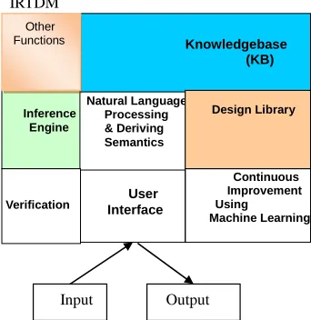
[image:7.595.86.257.91.267.2]Other Functions
Figure 4. IRTDM—Intelligent Agent for requirement mo- del to design model mapping. Shows all the key blocks. The KB and Design Library can reside outside. Input is mainly the requirement model and output is mainly the design structure and blocks.
1) Use of appropriate rules and semantics to help map/ transform one architectural style to another (e.g. Data- flow architecture to Layered architecture).
2) Use of Learning to improve the outcome. 3) Use of Verification to ensure correctness.
Architectures for which direct mapping does not exists, the mapping process becomes complex. The designers approach the translation of requirements to design for such cases using their knowledge, more analyses and considering more architectural tradeoffs. Although there is no simple steps like steps #a to steps #f as mentioned in Section 2 for DFD based mapping, the designer’s ap- proach can be captured into similar flow and steps but with more natural language descriptions. Thus, for such cases, the issue of using NLP becomes more important and semantics & rules become more complex.
The learning over time can be implemented using any standard good learning algorithms. The verification pro- cess can be implemented by allowing performing some basic tests on the constructed system. Each component will have netlist or behavioral model representation which can take input vectors and verify the outputs with some predefined expected outputs (in compliance with the specification). In some cases, formal verification can be done using formal mathematical specification of the software.
6. Future Works
The semantics represented by FOL and other similar techniques are good but they work satisfactorily mainly for small domain. As shown in Section 4.3, we need to define semantics for almost everything i.e. existing
schemes do not allow to automatically derive new se- mantics from semantics of existing words. In ([14,15]) we have mentioned that while traditional approaches to Natural Language Understanding (NLU) have been ap- plied over the past 50 years and have had some good successes mainly in a small domain, results show insig- nificant advancement, in general, and NLU remains a complex open problem. NLU complexity is mainly re- lated to semantics: abstraction, representation, real meaning, and computational complexity. We argued that while existing approaches are great in solving some spe- cific problems, they do not seem to address key Natural Language problems in a practical and natural way. In [16], we proposed a Semantic Engine using Brain-Like
approach(SEBLA) that uses Brain-Like algorithms to
solve the key NLU problem (i.e. the semantic problem) as well as its sub-problems.
SEBLA can calculate semantics of sentences using the semantics of words and the semantics of a paragraph using the semantics of the sentences. Enhanced seman- tics capability is needed to handle complex mapping cases mentioned in Section 5. We plan to use SEBLA for such cases.
We also plan to use SEBLA to automate/partially automate the implementation of the architecture into final software form (i.e. converting the architecture into op- erational software). Note that the automation presented in this paper is not the implementation in final software form; it is rather automating the mapping to design structure or architecture or blueprint of the desired sys- tem.
7. Conclusions
IRTDM (Intelligent Agent based requirement model to design model mapping) will significantly help today’s large software development process. It takes long time to manually map the requirement model to a design model. As the software size gets bigger and bigger (a common trend in the industry), this process will become much more complex, and need for an automation of this proc- ess will become mandatory. In fact, automation is al- ready mandatory to handle existing software design/de- velopment if we focus on the design for the bottom 90% people (the so-called Base of the pyramid people, BOP). IRTDM will also increase the reliability and correct- ness of the said mapping and associated software. More- over, with Natural Language Processing/Understanding and Artificial Intelligence (AI), the IA (Intelligent Agent) can map the design model to high level design compo- nents, thus further providing significant help in already very complex software engineering process.
lower price for buying new software; thus allowing many more people in the world to enjoy the benefits of the In- formation Age.
We have emphasized the need for enhanced Natural Language Processing/Understanding to better handle se- mantics, especially, for the complex software develop- ment cases. Use of natural semantics (e.g. SEBLA [16]) is the key to achieve this which we plan to do next.
REFERENCES
[1] E. Khan, “Internet for Everyone: Reshaping the Glob-al Economy by Bridging the Digital Divide,” 2011.
[2] G. Abowd et al., “Structural Modeling: An Application Framework and Development Process for Flight Simu- lators,” CMU Technical Report CMU/SEI-93-TR-014, 1993.
[3] Structured Analysis.
http://en.wikipedia.org/wiki/Structured_analysis
[4] D. Garlan and M. Shaw, “An Introduction to Software Architecture,” Advances in Software Engineering and Knowledge Engineering, Vol. I, World Scientific Pub-lishing Company, 1995.
[5] F. Buschmann, et al., “Pattern-Oriented Software Archi-tecture, A System of Patterns,” Wiley, 2007.
[6] “Architecture Analysis and Design Language, Software (AADL),” Engineering Institute, Carnegie-Mellon Uni- versity, 2004.
[7] P. Clements, “A Survey of Architectural Description Lan- guages,” Paul C. Clements, Software Architecture, Soft- ware Engineering Institute, 1996.
[8] S. Greenspan, et al., “A Requirements Modeling Langua-
ge and Its Logic,” Information Systems, Vol. 11, No. 1, 1986, pp. 9-23.
http://dx.doi.org/10.1016/0306-4379(86)90020-7
[9] J. Rumbaugh, et al., “The Unified Modeling Language Reference Manual,” 2nd Edition, Addison-Wesley, 2004.
[10] “Process Model Requirements Gap Analyzer,” 2012. http://www.accenture.com/SiteCollectionDocuments/PDF /Accenture-Process-Model-Requirements-Gap-Analyzer. pdf
[11] H. E. Okud, et al., “Experimental Development Based on Mapping Rule between Requirements Analysis Model and Web Framework Specific Design Model,” Springer-Plus Journal, Vol. 2, 2013, p. 123.
http://dx.doi.org/10.1186/2193-1801-2-123
[12] R. Pressman, “Software Engineering: A Practitioner’s Approach,” McGrawHill, 2010.
[13] D. Jurafsky, et al., “Speech and Language Processing: An Introduction to Natural Language Processing, Computa- tional Linguistics and Speech Recognition,” Pearson/ Prentice Hall, 2009.
[14] E. Khan, “Natural Language Based Human Computer Interaction: A Necessity for Mobile Devices,” Interna-tional Journal of Computers and Communications, 2012.
[15] E. Khan, “Addressing Big Data Problems using Seman-tics and Natural Language Understanding,” 12th Wseas International Conference on Telecommunications and Informatics (Tele-Info ‘13), Baltimore, September 17-19, 2013.
![Figure 1. Flow-Oriented Requirement Modeling to Data-Flow Architecture Mapping (Courtesy [12])](https://thumb-us.123doks.com/thumbv2/123dok_us/7944311.751204/3.595.62.534.84.385/figure-flow-oriented-requirement-modeling-architecture-mapping-courtesy.webp)