Finite Element Analysis of Steel C15 Plate Using
CST Element
J.D. Nallasivam
1, B. Babu
2, K. Kandasamy
3, Deepu Dinesan
4 1, 2, 3, 4Assistant Professor, Department Of Mechanical Engineering, Rathinam Technical Campus, Coimbatore
Abstract: Various numerical techniques have been used to solve the partial differential equations and give the solution to different engineering applications. Well-known method of finite element methods find the approximate solution by discredits the physical domain into number of elements. In this paper finite element analysis carried out for steel C15, plate using CST element. A three noded triangular element is known as constant strain triangular element. The element is called CST because it has a constant strain throughout it. Steel C15 is used as a material under stressed parts. The material used in making of sprockets, steel tubes and steel plates etc. This paper mainly focuses on find out the deformation for each node and stresses for each CST element of steel C15 plate using FEM technique by calculation. Another way to compute the stress and deformation for steel C15 plate is ANSYS 12.0 software. Finally, the results obtained in calculation and ANSYS software was compared. Keywords:FEA of steel C15 plate, CST Element, plane stress problem, two dimensional steel C15 plate, Stress and Deformation analysis.
I. INTRODUCTION
Numerical methods are the most important techniques in the simulation of real circumstance in solving problems. Various kinds of differential or partial governing equations have been derived for the physical phenomena. The most familiar approximation methods are the finite element method (FEM), finite difference method (FDM) and finite volume method (FVM). The analytical methods consider a differential element and develop the governing equations usually in the form of partial differential equation. It is often rare to have accurate solution to this partial differential equation in view of complex geometry. FEM is the primary methods for simulation of parts. Using FEM, the deformation and stress could be found for the problem under structural analysis [1] [3]. In this paper, stresses and deformation of steel C15 plate is computed using CST element. The steel plate is having two CST elements. First, strain-displacement matrix [B] and stress-strain relationship matrix [D] for plane stress condition is derived. Based on the initial conditions and boundary conditions, the global matrix is reduced to find out the displacements in x direction and y direction. Finally, normal stresses and shear stresses of steel C15 plate were computed for each element and compared the result with ANSYS 12.0.
II. PROBLEMDEFINITION
The problem is to find the nodal displacements and element stresses for the two-dimensional loaded steel C15 plate as shown in Fig.2.1.
Assume plane stress condition with thickness of 10 mm.
Young’s modulus, E = 2.080 X 10⁵ N/mm2 Poisson’s ratio,
= 0.32Thickness, t = 10 mm Point load, P = 500 KN
Body force is neglected in comparison with external force.
III. COMPUTATIONOFDISPLACEMENTANDSTRESSES
Figure.3.2: Nodal displacements at node 1, 2, 3 and 4 Figure.3.3: Nodal displacements for Element number 1 For element 1(Fig.3.3),
Nodal displacements are u1, v1, u2, v2, u3 v3 Take node 1 is origin,
(x1, y1) = (0, 0) (x2, y2) = (150, 0) (x3, y3) = (150, 100)
Stiffness matrix, [K] = [B]T [D] [B] At Where, A = Area of the triangular element.
A = 3 3 2 2 1 1 1 1 1 2 1 y x y x y x
= 7500 mm2 Strain – Displacement matrix,
3 3 2 2 1 1 3 2 1 3 2 1 0 0 0 0 0 0 2 1 q r q r q r r r r q q q A B
B = 0.00330 3 2 3 2 0 3 0 3 0 0 0 0 0 0 2 0 2 Stress – strain relationship matrix [D] for plane stress problem is,
2 1 0 0 0 1 0 1 1 D 2 E[D] = 2.3173 x 10⁵
34 . 0 0 0 0 1 32 . 0 0 32 . 0 1
K1190575 9 0 9 92 . 1 0 92 . 1 0 06 . 3 04 . 2 06 . 3 04 . 2 0 9 04 . 2 36 . 10 96 . 3 36 . 1 92 . 1 92 . 1 06 . 3 96 . 3 06 . 7 04 . 2 4 0 04 . 2 36 . 1 04 . 2 36 . 1 0 92 . 1 0 92 . 1 4 0 4 For element (2), Stiffness matrix [K]2
K 2190575 36 . 10 96 . 3 36 . 1 92 . 1 9 04 . 2 96 . 3 06 . 7 04 . 2 4 92 . 1 06 . 3 36 . 1 04 . 2 36 . 1 0 0 04 . 2 92 . 1 4 0 4 92 . 1 0 9 92 . 1 0 92 . 1 9 0 04 . 2 06 . 3 04 . 2 0 0 06 . 3
General finite element equation is,
[F] = [K] [U] [K] = Global stiffness matrix
Force, [F] = [F1x F1y F2x F2y F3x F3y F4x F4y]T Displacement, [U] = [u1 v1 u2 v2 u3 v3]T
Based on boundary and initial condition, u1 = v1 = u4= v4 = 0 u2 0, v2 = 0 F3y = - 500 x 103N Equation 7 is reduced to,
3 2 3 v u u 36 . 10 0 92 . 1 0 06 . 7 06 . 3 92 . 1 06 . 3 06 . 7 190575 10 500 0 0 3 X
Solving above equation,
u1 = 0 mm v1 = 0 mm
u2 = 0.09041 mm v2 = 0 mm
u3 = 0.03919 mm v3 = - 0.26999 mm u4 = 0 mm v4 = 0 mm Stress for element 1,
[1] = [D] [B] [u]
2 2248 . 40 1247 . 579 3449 . 60 x mm N xy y
Stress for element 2,
2 = [D] [B] [u]IV. CSTELEMENTBYANSYS
ANSYS 12.0 software has been used for solving the different engineering problem in the field of structural, thermal and fluid dynamics. The most of the problem can be solved by using two dimensional rather than three dimensional. In the structural problem, the unknown variables are deformation, stress and strain etc., In thermal problem, temperature distribution and heat flux throughtout the structure are unknown variables and in fluid problem, velocity and pressure distribution are unknown variables.
[image:5.612.201.373.150.293.2]
Figure 4.1: Two dimensional Finite element model (CST) of steel C15 plate
[image:5.612.126.485.419.581.2]In this paper, steel C15 plate can be used and convert the physical model into finite element model by discretization. The Fig.4.1 shows that the two dimensional steel plate is discretizised into two CST element. Boundary condition, Initial condition and loading has applied to the specific problem and solved by ANSYS 12.0. The result can be obtained as deformation, stress and shear stress from general post processor. The deformation result for X component (Fig.4.2) and Y component (Fig.4.3) was predicted by ANSYS 12.0. The value of X-component deformation varying from 0 to 0.089228 mm and the value of Y-component deformation varying from -0.266462 to 0 mm. The deformation along X and Y component is u1, u2, u3, u4 and v1, v2, v3, v4 at nodes 1,2,3 and 4 respectively.
Figure 4.2: X- Component Deformation of Figure 4.3: Y- Component Deformation of Steel C15 plate. Steel C15 plate. The values of X and Y components that found in ANSYS are showed in the following table:
Table: 4.1 Displacement value in X and Y directions NODE
No.
DISPLACEMENT
X-Component Y-Component 1 u1= 0 v1= 0
2 u2= 0.089228 v2= 0
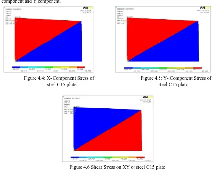
The Fig.4.4 and Fig.4.5 shows that stress in X component is varying from -59.746 to 59.746 N/mm2 and stress variation along with Y component is varying from -573.36 to 19.119 N/mm2. Stress for first element is minimum value compared to second element for both X component and Y component.
Figure 4.4: X- Component Stress of Figure 4.5: Y- Component Stress of steel C15 plate steel C15 plate
Figure 4.6 Shear Stress on XY of steel C15 plate
From the Fig.4.6, The shear stress is varied from -139.96 to 39.830 N/mm2. Here the first element has the maximum shear stress and element number 2 has minimum value. The following table shows the stress and shear value computed from ANSYS 12.0.
Table: 4.2 Normal Stress and Shear Stress value of elements 1 and 2
ELEMENT NO. STRESS SHEAR STRESS
X-Component Y-Component XY- Component 1 σx= - 59.746 σy= - 573.36 τxy= - 39.830 2 σx= 59.746 σy= 19.119 τxy= - 139.96
V. RESULTSANDDISCUSSIONS
From the table 5.1, we observed that calculated values of displacement is maximum than the values from ANSYS Software for both X and Y direction. In addition, we predicted that deviations in percentage for the displacements are constant. From the table 5.2, we got a maximum value of stresses by calculation as in the case of previous displacement values. More over the percentage of deviation is remain the same for all the Stresses and Shear stress values.
Table: 5.1 Comparison of Displacement Values (Calculated and ANSYS)
OBSERVATION CALCULATED ANSYS DEVIATION IN %
Node No: 1 2 3 4 1 2 3 4 1 2 3 4
[image:6.612.50.575.669.730.2]Table: 5.2 Comparison of Stress and Shear Stress Values (Calculated and ANSYS)
OBSERVATION CALCULATED ANSYS DEVIATION IN %
Element No: 1 2 1 2 1 2
Stress at X -60.3449 60.3449 -59.746 59.746 -0.99 -0.99 Stress at Y -579.1247 19.3131 -573.36 19.119 -0.99 -1.00 Shear stress at XY -40.2248 -141.3643 -39.830 -139.96 -0.98 -0.99
VI. CONCLUSIONS
This paper mainly focused on predicts the deformation and various stresses of steel C15 plate subjected to point load. The deformation and complex stress analysis is computed by finite element method using the three nodes Constant Strain Triangle (CST). Analysis has been performed using analysis software ANSYS for the same structure, boundary condition and loading. The comparison study performed for deformation and stress value by calculations and ANSYS Software. ANSYS saves lot of time and computational efforts. This approach lends simplicity of development and retains uniformity with other complex. From the results and discussions, the percentage of deviation is minimal for both deformation and stresses. Finally, we conclude that the results obtained from FEM (Calculation) and ANSYS Software using CST as a modeling element are closely converging and are in good agreement with the solution.
REFERENCES
[1] S.S Rao, “The Finite Element Method in Engineering”, Fourth Edition, Elsevier Science and Technology. [2] S.Senthil, “Finite Element Analysis”, Seventh Edition, Lakshmi Publications.
[3] P.Seshu, Text book of “Finite Element Analysis”, Published by PHI Learning Private Limited, 2010. [4] Semie Addisu Gezahegn, “Numerical modeling of thin plates using finite element method”, 2010.
[5] Xuan HN, Rabczuk T, Alain SPA, Dedongnie JF (2007). “A smoothed finite element method for plate analysis”, Computer Methods Appl. Mech. Eng., 197: 13-16, 1184-1203.