©IJRASET: All Rights are Reserved
1529
Design, Analysis and Fabrication of Steering
System Used in Student Formula Car
Chinmay Raut, Rahul Chettiar1, Nikunj Shah2, Chandraprakash Prasad3, Dhiraj Bhandarkar4
1,2,3,4Mechanical Engineering Department, SJCEM, Palghar, Maharashtra, India
Abstract: This thesis aims to highlight the design, modelling and explore the theories and techniques behind procedures of developing a rack and pinion steering system for student formula vehicle. This newly designed mechanism will be used in 2017 SAE SUPRA EVENT. Various systems were studied and a simple but very effective rack and pinion steering system was designed with the consideration of the driver. A steering mechanism is a mechanism that helps a vehicle to give direction, the normal standard steering systems available in the market are if ratio 16:1 which means for complete turn of vehicle the steering wheel must be rotated 4 times, a power steering overcomes the problem of rotation and does the full turn in 2 revolutions of steering wheel. As per the guidelines of the SAE SUPRA event power steering was not allowed, hence a need arise to manufacture a steering system that could take a full turn in half rotation of steering wheel, this was accomplished by using a rack and pinion steering system with low steering ratio. The mechanism is designed with a view to keep the steering ratio low as possible so the various tentative events like auto cross can be easily be faced. The mechanism has been designed, analysed, manufactured, tested and installed successfully.
I. INTRODUCTION
SUPRA competition is a good initiative taken by SAE INDIA which not only gives a platform to the students to show their technical abilities but also brings them in partial touch with the important engineering field like Design, Manufacturing, Quality, Sales and Marketing.
Challenge to the engineering students is to constantly innovate and bring out changes in Weight, Fuel saving and much more aspects. For this competition all the students have to follow the rule book and design according to the guidelines given in the rule book. Steering System is the collection of components, linkages, etc. which allows any vehicle to follow the desired course.
The primary purpose of the steering system is to allow the driver to guide the vehicle.
The most common steering arrangements to turn front wheels using a hand operated steering wheel which is positioned in front of the driver via the steering column which may contain universal joint (which may also be a part of the collapsible steering column design), to allow it to deviate somewhat from a straight line .other arrangements are sometimes found on different vehicles, for example, a tiller or rear wheel steering, tracked vehicles such as bulldozers and tanks usually employ differential steering system A basic steering system has 5 main parts: Steering box, Linkages, Knuckle or upright, Column Shaft & Steering wheel.
When the driver turns the steering wheel, a shaft from the steering column turns a steering gear. The steering gear moves tie rods that connect to the front wheels. The tie rods moves the front wheels to turn the vehicle right or left.
A. Basic geometry
The basic aim of steering is to ensure that the wheels are pointing in the desired directions. This is typically achieved by a series of linkages, rods, pivots and gears. One of the fundamental concepts is that of caster angle– each wheel is steered with a pivot point ahead of the wheel; this makes the steering tend to be self-centering towards the direction of travel.
The steering linkages connecting the steering box and the wheels usually conform to a variation of Ackermann steering geometry, to account for the fact that in a turn, the inner wheel is actually travelling a path of smaller radius than the outer wheel, so that the degree of toe suitable for driving in a straight path is not suitable for turns. The angle the wheels make with the vertical plane also influences steering dynamics as do the tires.
B. Rack and pinion steering system
©IJRASET: All Rights are Reserved
1530
kept in a housing known as the steering gear box and the ends of the rack are connected to the wheels by tie rods.
C. Design by track
Certain rules need to be followed before designing the steerng according to SUPRA SAEINDIA Rulebook.
SUPRA autocross track, skid pad track where studied in order to design Ackerman geometry thereby deciding inner and outer wheels turning angle and turning radius of the vehicle, steer arm length and rack travel.
[image:3.612.219.404.171.366.2]––––
Figure: Wheel Alignment
II. GEOMETRY
A. Camber Angle
As shown on the following figure, the camber angle is the angle that the inclination of the vehicle’s tyres makes with the vertical axis. In this case the camber is negative as the top of the tyre leans in towards the centre of the car. A positive camber is the opposite of this. Increasing the positive camber will enlarge the slip angle for a specific cornering force, decrease the largest possible cornering force possible by the vehicle but will also slow down the onset of ‘breakaway’ which is assumed to mean the car starting to slide. On the other hand, by increasing negative camber the opposite will occur with a higher cornering force and less time for the car to break away. It should also be mentioned though that generally vehicles will be designed with a relatively small camber angle statically applied.
Figure : Camber Angle
B. Kingpin Inclination
[image:3.612.215.391.505.641.2]©IJRASET: All Rights are Reserved
1531
scrub radius. It is the lateral measurement between the meeting point of the centre of the tyre’s contact patch and the kingpin axis, with the ground plane. Convention is that positive offset will be when the kingpin offset is outboard of the kingpin axis.
C. Caster Angle
Caster angle also relates to the kingpin or steering axis although describes the angle of it when viewing the vehicle from side on. As seen above, it is the angle that the kingpin axis makes with the vertical. It is positive when the kingpin axis meets the ground ahead of the vertical 30 axis drawn through the wheel centre, if the car is assumed to be facing right, the caster angle is therefore negative. In a vehicle with negative caster angle, the steering wheels will tend to self-align as the vehicle moves forward. Another term that is often associated with the caster angle is the caster offset or mechanical trail.
D. Toe Angle
[image:4.612.190.424.329.413.2]Toe angle is the angle that a wheel makes with a line drawn parallel to the length of the car, when viewed from above. This concept is seen below in figure. When the front wheels point away from each other, the condition is called toe out whereas when the front wheels point inwards, the vehicle is said to have toe in. Generally designers will opt for toe in for the reason being that when the vehicle experiences an upsetting force such as a bump or a wind gust, the toe in will promote stability as the front wheels naturally want to steer into a location central to the car’s body. Toe out on the other hand will produce some very unstable behavior under these conditions when the slip angle of the more heavily laden wheel increases. In general, toe in will provide greater straight line stability whereas a controlled amount of toe out can improve the car’s turn in ability to a corner.
Figure : Toe Angle
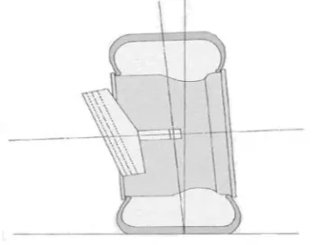
E. Ackermann Geometry
The Ackermann steering geometry takes its name from a London agent that patented the design in 1816. The geometry allows the outer front wheel to cover a larger radius than the inside wheel. As a result both wheels will follow individual radii without skidding or scrubbing as the vehicle corners.
Figure Ackermann Geometry
F. Physical design of components
All components modelled in Solid Works followed by finite element analysis (FEA) in ANSYS to verify the design is safe and can withstand all loads imposed by typical vehicle use. A suitable factor of safety (FOS) will need to be chosen in order for this to happen
If components fail to meet required factor of safety, appropriate revisions will be made to the design before being tested again, thus ensuring the final design is adequate
Once components are finalized the suspension and steering systems are to be assembled in 3d space to aid in the packaging of other
[image:4.612.197.416.469.611.2]©IJRASET: All Rights are Reserved
1532
vehicle systems and to verify that there is no fouling of components within the suspension and steering mechanisms as well as other vehicle parts
If fouling is present suitable redesign will follow before the reconfigured parts are again tested in an FEA.
This geometry, the steering arms on the front wheels must angle inward and meet at the centre of the rear axle. These days only a selected number of vehicles will employ full Ackermann geometry. This is because as cornering speed increases, the wheels of a car will adopt slip angles and effects of the Ackermann geometry will become obsolete. For these reasons only slower vehicles that require restricted turning circles will be the ones to use this full geometry whereas the majority of all modern vehicles will only utilize a small amount of Ackermann compensation.
III. DESIGN DESCRIPTION
The function of steering system is to steer the front wheels in response to driver command inputs in order to provide overall directional control of vehicle.
Design steps involved: Identify vehicle requirement Geometry set up
Geometry validation Designing of mechanism
A. Identify vehicle requirement
The first step is to identify the system requirements. Since objective of our project is to design an efficient steering system which is going to be a part of the prestigious event called SUPRA.
The vehicle chassis was designed according to the rule book of SUPRA-2017. And following parameters were finalized based on driver safety and comfort ability:
· Front track width: 47.2" · Rear track width: 39.4" ·Wheel base (l): 63"
Using these basic parameters we started our designing.
B. Geometry setup
It is the most important step of designing because steering geometry actually decides the manoeuvrability of vehicle during different driving conditions like bump, jounce and cornering etc.
A suspension system also has significant effect on steering ability of vehicle so; a combined effort in suspension geometry and steering geometry were taken in order to design efficient system.
The geometry set up was performed in following steps:
C. Suspension geometry set up:
Designing of steering geometry involves a brief study of suspension system of the vehicle. The various parameters like static camber, camber change rate, static toe and toe change rate and roll steer during dynamic conditions are to be consider for efficient design of the system.
As mentioned earlier a optimum suspension geometry was finalized by studying the different behaviour parameters of the system during different dynamic conditions using LOTUS software.
Lots of iterations were performed and at the end of this stage following performance parameters were finalized for efficient suspension system:
· Steering arm length (lst): 110mm
· Ackerman angle (α): 200
D. Steering geometry setup
©IJRASET: All Rights are Reserved
1533
LOTUS software was used for simulation.
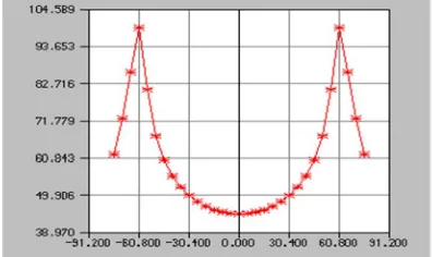
[image:6.612.188.425.99.323.2]Following figure shows the graphical validation of geometry:
Figure Ackermann Principle
Due to compact design it was difficult to achieve 100% Ackerman geometry. So, a simulation was performed using LOTUS software to observe % Ackerman variation during dynamic conditions.
Parameters are:
Table 2- Track Parameters
Parameter Value
Track width (b) 1200mm = 47.2’’
wheel base (l) 1600 mm=63’’
Steering arm length(lst) 110mm
Ackerman angle (α) 200
[image:6.612.193.391.548.666.2]Following graph explains the Ackerman % that geometry is capable to achieve during dynamic conditions:
Figure : Percentage Ackerman geometry variation during cornering
©IJRASET: All Rights are Reserved
1534
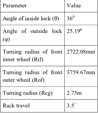
Table 3-Basic Steering Parameters
Parameter Value
Angle of inside lock (θ) 360
Angle of outside lock
(φ)
25.190
Turning radius of front inner wheel (Rif)
2722.08mm
Turning radius of front outer wheel (Rof)
3759.67mm
Turning radius (Rcg) 2.75m Rack travel 3.5’’
E. Geometry validation
The geometry validation was done by performing the analytical treatment. The concept of reverse engineering was applied in order to validate the designed geometry.
The following calculations were performed in order to validate the geometry: Required condition is:
Angle of inside lock (θ) = 360
According to Ackermann Geometry for perfect steering is given by:
( )− ( ) =
Hence rearranging and substituting values in above equation;
cot (φ) = ( )+ cot (θ)
cot (φ) = ( ) + cot (36)
(φ) = 25.190
Also,
( − )
( + )
[ |−2] =
Putting values in above equation;
(α) = 20.730
Inner Turning Radius,(Rif) = = 1600/ sin (36) (Rif) = 2722.08 mm
©IJRASET: All Rights are Reserved
1535
Figure.: Turning Radius and Angle
Hence by comparing both graphical and analytical data we can conclude that the both values are converging thus, the system design is accurate.
F. Design of mechanism
We are using rack and pinion mechanism because of oblivious advantages of reduced complexity, ease of construction and less space requirement compare to other steering mechanisms. The analytical steps involved in designing if rack and pinion systems are as follow:
G. Selection of gear tooth profile
A gear tooth profile was selected based on BIS (Bureau of Indian Standard) recommendation and the manufacturability. A 200 full
depth involute profile system was selected because of the following advantages: It reduces the risk of undercutting
It reduces the interference
Due to increase in pressure angle, the tooth becomes slightly broader at the root this makes the tooth stronger and increases its load carrying capacity. It provides better length of contact.
The properties of teeth of 200 full depth involute profile system are as follow: Table - Empirical Relation Of Pinion
Parameter Values
Pressure angle (φ) 200
Addendum (ha) M
Dedendum (ha) 1.25m Clearance (c) 0.25m Working depth 2m
Whole depth 2.25m Tooth thickness 1.5708m
H. Minimum number of teeth on pinion:
The minimum number of teeth required on pinion in order to avoid the interference was computed using following relation: Zp = (
∗ )
©IJRASET: All Rights are Reserved
1536
Zp = ( ∗ ) = Zp = 17.09 ~18 nos.
Hence minimum numbers of teeth on pinion are: 18nos. Assume, Zg =29 nos.
I. Selection of material
The materials used in the steering system target precise operation and light weight components. Although precision and weight are the top priorities, cost, manufacturability, and reliability were also considered.
Precision in the steering system is derived from high manufacturing tolerances and minimal deflection. Defection in any component leads to steer compliance, resulting in an unresponsive steering system
While deciding material for the steering system design, the system can be divided in to parts and analyzed individually as per their functional requirements.
We can divide the system into following parts or subsystems.
1) Steering column i.e. shaft
2) Steering rack
3) Pinion gear
4) Steering Wheel: Diameter: 12”
5) Universal Join
6) Energy dissipation management during collisions
7) Provide mounting for other instruments
8) Offer height and length as per the driver comfort
When the driver turns the steering wheel, the column rotates the pinion gear and the rack moves laterally. The track rods are put into action, shifting the wheels. The tie rods are used to link the steering gear to the steering knuckle.
The tie rod ends are a ball and socket design that allows the tie rod to flex up and down with the movement of the front suspension. Tie rods should be inspected for excessive movement, grease seal tears, or any visible wear.
In rack and pinion steering mechanisms, where the steering wheel turns the pinion gear; the pinion moves the rack, which is a linear gear that meshes with the pinion, converting circular motion into linear motion along the transverse axis of the car. In high performance steering systems the steering column is mainly manufactured from carbon fiber, Titanium or aluminum. The steering rack and pinion is generally made from aluminum.
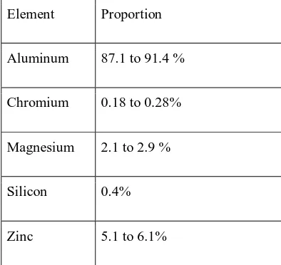
[image:9.612.206.403.521.707.2]The use of aluminum offers lesser weight of the assembly, cheaper in cost than titanium and carbon fiber and is easy to machine. After considering all these parameters it was observed that Aluminum t6 7075provides a required strength, it is easily available and excellent mach inability hence we decided to use it for our purpose:
Table 5 -Chemical properties of Al t6 7075 Element Proportion
Aluminum 87.1 to 91.4 %
Chromium 0.18 to 0.28%
Magnesium 2.1 to 2.9 %
Silicon 0.4%
©IJRASET: All Rights are Reserved
1537
Table 6 - · Physical properties of Al t6 7075[3] Property Value
Density A
Hardness: 1. BHN 2.Knoop 3.Rockwell (A)
150
191 53.5
Ultimate tensile strength (Sot)
541 MPa
Yield strength (S) 468 MPa
Modulus of elasticity (E) 71.7 GPa
Poisson's ratio 0.33
Melting point temperature 4770
J. Design of gear pair
It is necessary to design rack and pinion system in such a way that, it must provide required aligning torque while cornering without failure. The system was designed against bending as well as pitting failure.
K. Beam strength
Beam strength of gear tooth is the maximum tangential load that gear tooth can take without tooth damage.
L. Assumptions in analysis of beam strength 1) The full load is acting at the tip of a single tooth
2) The effect of radial force is neglected
3) The load is uniformly distributed across the full face width
4) Effect of stress concentration is neglected
5) Frictional force due to teeth sliding are neglected
M. Analytical calculations
1) bending endurance strength of pinion (σbp): (σbp) = (Sut)/3 = 541/3 = 180.33 2)bending endurance strength of gear (σbg): (σbg) = (Sut)/3 = 541/3 = 180.33 3) Lewis form factor (Y):
1. = 0.484 - (2.87/ Zp) = 0.484 - (2.87/18) . = 0.7717
2. Yg = 0.484 - (2.87/ Zg) = 0.484 - (2.87/29) Yg = 0.3850
As,
Σbp*. <σbg* Yg
©IJRASET: All Rights are Reserved
1538
Assuming b = 10*m, The beam strength is given by,
Pb = σbp*b*m*y
Pb = 180.33*10*m*m*0.3246 Pb = 585.35 m2 N
N. Wear strength
The failure of the gear tooth due to pitting occurs when the contact stresses between two meshing teeth exceed the surface endurance strength of the material. Pitting is a surface fatigue failure, characterized by small pits on the surface of the gear tooth. In order to avoid this type of failure, the proportions of the gear tooth and surface properties such as surface hardness, should be selected in such a way that the wear strength of the gear tooth is more than the effective load between the meshing teeth. The analysis of the wear strength was done by Earle Buckingham, in his paper.
Buckingham’s theory is based on hertz theory of contact stresses. From his theory we can conclude that Wear strength of a gear tooth is the maximum tangential load the gear tooth can take without causing a pitting failure.
Pw = b.Q.dp.k
Q = Ratio factor for external gear pair = [(2.Zg) / (Zg + Zp) ] Here Zg = 29, Zp = 18 So that Q = 1.234
k = [ c2. cosϕsinϕ. (1/є1+ 1/є2)] / 1.4
k = {[(0.27). (9.81). (150/100)]2. Cos (20).sin(20). (1/71700)}/1.4
k = 0.45. (150/100)2
k = 0.45. (150/100)2 k = 1.0125
Hence wear strength can be calculated as follow; Pw = 224.89m2 N
O. Effective load:
Effective load was calculated based on functional requirement of the system.
While cornering the drive applies an effort to steer the vehicle, it is a necessary effort require to proved the alignment torque to overcome the friction couple generated by the reaction forces acting at a point of contact of wheel with the surface of road.
The friction couple is generated because of offset between wheel contact point and traction point and also because of castor trail. As mentioned earlier while setting geometry for suspension system following parameters were finalized to improve system performance
1) Steering axis inclination: 00. 2) Castor angle : 00
From calculations; Scrub radius: 60 mm Castor trail: 27.299 mm
Assuming human tendency to apply brakes while turning, we considered 50% distribution of weight. Thus the reactions forces are computed based on above assumptions are calculated as follow: So, FT = 50% wt of vehicle = 1226.25 N on both suspension joints.
FIGURE: Castor Trail And Scrub Radius Calculations
©IJRASET: All Rights are Reserved
1539
Moment to overcome offset of SAI axis = (FZR + FZL). d.sinλ.sinδ
= (1226.25)*60*sin4.21*sin36 = 3174.808 N-mm
Aligning torque required to overcome caster trail offset is given by;
Moment to overcome offset of caster trail= (FZR – FZL). d.sinμ.cosδ
= (367.94)*60*sin3*cos36 = 934.74 N-mm
Hence,
MT = 3174.80 +934.74 MT = 4109.55 N-mm
Fig.6.4.9 B: Lateral Forces on Wheel While Cornering
The tangential force across the pinion is given by; Meff= Ft * steering arm length
Hence, Ft = 585.35 N
From design data book;
For accurate mounting and moderate shocks: Ka = Application factor = 1
Km = Load concentration factor = 1.3 Kv = velocity factor = 1
Peff = (Ka * Km)* Ft / Kv
Peff = 760.955 N
P. Estimation of module
As gear pair is weaker in wear than in bending so, system must be design against wear failure
Assuming factor of safety (Nf) = 1.8 For given system;
Pw = Nf * Peff
224.89m2 = 1.8*760.955
m=2.5mm
©IJRASET: All Rights are Reserved
1540
TABLE 7-Dimensions of Pinion Parameter Values d (mm) 42mm
Addendum(ha) 2.5mm Dedendum (hf) 2.5mm Face width(b) 24mm Module(m) 2.5mm Zp 18
TABLE8 -Dimensions of Rack: Parameter Values
d (mm) 20mm
Addendum(ha) 2.5mm
Dedendum (hf) 2.5mm
Face width(b) 24mm
Module(m) 2.5mm
Zp 29
IV. CONCLUSION
A. The project have been both challenging and rewarding. It required the knowledge gathered in many of the subjects pertaining to engineering studies and offered valuable practice in team working environment as well as good professional practice.
B. All the tasks set up for this project have been completed in the available time.
C. The design complies with the SAE SUPRA rulebook.
D. A complete test of steering system is done and is successful in its performance.
REFERENCES
[1] Saurabh Borse, Pranav Chille, Shubham Dabhade, Swapnil Deshmukh, Atul Kulkarni, “Design and Manufacturing of an effective steering system for ATV and performance enhancement using yoke-nut assembly”, NCMMM-2016, E-ISSN: 2321-9637,19 March 2016
[2] Prashant L Agrawal, Sahil Shaileshbhai Patel, Shivanshu Rajeshbhai Parmar, “Design and Simulation of Manual Rack and Pinion Steering System”, IJSART-Volume 2, Issue 7-July 2016
[3] Jock Allen Farrington, “Redesign of an FSAE Race Car’s Steering and Suspension System” October, 201
[4] R.P.Rajvardhan, S.R.Shankapal, S.M.Vijaykumar, “Effect of wheel geometry parameters on vehicle steering”, SAS TECH JOURNAL-Volume 9, Issue 2 ,September 201
[5] Daniel Nuviala Civera, “Description and design of the steering system for a Formula Student car” September 2009-201