Technology (IJRASET)
Improved Insulation Design Scheme for 145kv
Current Transformer with the Help of Electric
Field Analysis through Finite Element Method
Santosh Jain1 Ramchandra Hasabe2 Gopalsing Patil3
1
P.G student Dept. of Electrical Engg., Walchand College of Engineering, Sangli (M.S), India.
2
Asst. Professor Dept. of Electrical Engg., Walchand College of Engineering, Sangli (M.S), India.
3
Manager- Technology, Crompton Greaves Limited, Aurangabad (M.S), India.
Abstract— This paper proposes a new Capacitive graded bushing configuration for 145kV Live Tank Current Transformer which has lowest possible maximum electrical stress in it. Capacitive graded bushing breakdown is one of the major reasons of Current Transformer failures (In-service and at test bead). Since this bushing is heart of the current transformers so it is necessary to design it carefully and the electric stress distribution in capacitive graded bushing is primarily dependent on the geometry and dielectric properties of material. The main motive is to obtain the better design of a capacitive graded bushing which will have reduced electric stress as compared with the existing design. Capacitive graded bushing contains concentric aluminum foils which are isolated from each other by Oil Impregnated Paper (OIP). The partial capacitances (Combination of Series and Parallel) between these can be modified by adjusting the number of foils, its diameter, width and foil staggering also the thickness of dielectric material between foils. This stated grading configuration’s stress level is under the limit considering all practical conditions, taking the various literature, IEEE transactions and practical results as benchmark. This paper reveals the configuration which gives improved and optimal electric stress distribution in the designed bushing configuration and which ultimately reduces the oil volume content, cost of active part insulation and the porcelain housing as a whole product.
Keywords—Capacitive graded bushing, Bushing Foils, Electric Field, Electric Field Simulation, ElecNet, Finite Element Analysis.
I. INTRODUCTION
With the ever increasing competition in the global market, there are continuous efforts to reduce the insulation in current transformers. This requires greater efforts from the researchers’ and designers for precisely finding out the stress levels at various critical electrode configurations inside an instrument transformer under different voltage test levels and practical conditions. Advanced computational tools such as 2D finite element method are being used for perfect estimation of stress levels, which can be compared with standard withstand levels. The significance of electrical insulation in high voltage equipment goes on increasing as voltage levels are increasing day by day and so does the importance of insulation materials increased which lies in their opposition against voltage or electric field stresses.
Technology (IJRASET)
These foils build a series of co-axial cylindrical capacitors configuration and they are called as Capacitive graded bushings. The gap between foils is filled by the thick insulating paper and this paper provides the required mechanical strength to concentric cylindrical configuration [3].
Partial discharges are likely to start on the occurrence of overvoltage or surge, so as to ensure the safe operation it is necessary to examine the electric stress distribution of the bushing [5]. As voltage increases, more aluminum foils are required, hence the foil length, width and placement location become critical/ essential. The relative position of foil influences the electric field of the staggering region, adjacent and so partial discharges are predicted here. This paper proposes the electric stress calculation of developed Capacitive graded bushing configuration, which contains different foil location and length [3], [4]. This paper first deals with mathematical modeling of insulation system for capacitive voltage grading, then compares the electric stress simulation results with the existing configuration by the use of finite element method (FEM) software ElecNet (2D simulation).
II. A MATHEMATICAL MODEL OF A CURRENT TRANSFORMER INSULATION SYSTEM
Insulation system of Current Transformers is exposed to various dielectric stresses that can be hazardous if the dielectric strength of insulation is reduced. Electric field strength depends on the voltage distribution along the active part of CT bushings. The design process concerns the design of a system of electrostatic control shields for two parts of insulation and computing the electric field distribution in all elements of the insulation system of a Current Transformer [4].
The Capacitive graded bushing design is the most vital and critical part of manufacturing process of Current Transformer. So, designing this kind of bushing is a great challenge for the designers or engineers considering all technical and industrial constraints. The motive of these engineers is to design the best optimal configuration by means of least amount of raw materials and minimum cost of manufacturing process [5]. Capacitive grading bushings contain co-axial conductive foils, whose length, width and location are designed/ adjusted to have minimum electrical stress. The typical conic type foil configuration is shown in Figure 1. Taking into account the relation between electric potential and electric field intensity, the electric field in an insulation system is described by Laplace’s equation; the electric field in an insulation system (after introducing the scalar electric potential) [3],
= −∇ (1)
At the same time considering the proper boundary conditions. Where E is the electric field strength is described by the Laplace's equation,
∇ = 0 (2)
The partial capacitance value formed between the intermediate layers and also the potential on each plate or foil can be calculated by deriving the amount of stored electrical energy in it [3],
Technology (IJRASET)
Figure 1: Typical Conic Type Configuration The electrical energy stored between the plates or foils can be given by,
= .
2
(4)
The boundary conditions are values of potential of the The boundary conditions are values of potential of the CT pipe at 0kV and outer shield at 275kV; electrostatic shields are floating and the condition of the tangential electric field strength (Neuman's) at the boundary of the whole system with the surrounding air box. Applying the numerical finite element method in 2D systems makes it possible to solve this equation. The 2D analysis allows the estimation of the Electric field distribution in the whole system and which makes it possible to determine the maximum electric field strength in insulation. And because of its complex geometrical shape it could not be possible to determine it analytically.
[image:4.612.189.422.379.480.2]The biggest problem of modeling the physical product is to reproduce the real shape of the product which may be sometimes very complicated to model with different diameter and radius of actual model [5]. The capacitive graded bushing is stressed, as shown in Figure 2, radially and axially. These two stresses have a very vital and crucial role while designing the bushing configuration and thus designer or engineer should try to keep it in the acceptable limit while designing [2], so as to have the uniform and minimum electrical stress distribution in the bushing as well as in the complete product. The region between insulating paper and surrounding medium should also be considered as a critical area. As the radial stress is increased, it can cause severe breakdown of the insulating material, at the same time under certain conditions. While as axial stress increased may lead to surface discharges along the boundary surface. The boundary layer is stressed to flashover limit and which is lower as compared with the electric field strength of insulating materials stressed[4], where as the axial stress component of electric field strength in common more critical based on the earlier mentioned fact. Both these radial and axial component of the electric field strength are kept within an allowable value or limit of one (1) over which it can cause severe breakdowns & surface discharges.
Figure 2: Radial and Axial Stress in High Voltage Bushing
III. SIMULATION
Apart from analytical and clearance calculations, the in depth electrostatic stress analysis is a very important tool of a modern design philosophy. Previously old classical methods/ formulae were used to calculate the stresses at certain critical locations for e.g. bushing shield HV lead etc. However with the advent of EHV transmission lines, the insulation design is becoming more & more complex and important which cannot be easily analyzed by the classical/old methods. In the present design philosophy [8], a finite element method (FEM) based analysis is done through sophisticated software to accurately calculate the stresses in the 145kV live tank current transformer capacitive graded bushing.
A. ELECTROSTATIC SIMULATION
Technology (IJRASET)
Table 1. Material Properties of bushing components (Crompton Greaves Ltd, Aurangabad)
Figure 3: 2D view of 145kV live tank current transformer existing Capacitive graded bushing design
FIIV. CRITICAL FEATURES OF BUSHING DESIGN OF 145KV CURRENT TRANSFORMER
Understanding the electric stress and potential distribution is very essential for the design and improvement of high voltage current transformer insulation design. Insulation failure and their effects can be reduced and the quantity and grade of insulating material can be optimized if the distribution of the electric field is known. Voltage is stated as the dot product line integral of the electric field strength along a definite or specified path in an electric field. The voltage has no spatial direction therefore it as a scalar quantity [6]. Voltage is identical with potential difference in an electrostatic field only. Electric field strength is defined as the magnitude of the electric field at a point in the field. The electric field is a vector of electric flux density or field of electric field strength. Its synonyms used are voltage gradient, and potential gradient [6].
The potential gradient is a vector quantity whose direction is normal to the equipotential surface, in the direction of decreasing potential, and of which the magnitude gives the rate of variation of the potential. The equigradient line or contour defined as the locus of points having the same potential or voltage gradient or electric field strength magnitude at a given time.. The analytical methods are restricted to problems with simple geometries only. Whereas the numerical methods offer general applicability to the object has been the area of intense research. From the past thirty five years various numerical methods have been developed because of advancement in powerful computers [7]. The collective idea in the numerical methods is the reduction of the governing field or object equation or an equivalent integral formulation into a linear system of equations. These methods can be classified in two groups: the methods where approximations are to be made completely through the region B: and the methods where approximations are to be prepared only on the boundary dB. The finite difference (FDM) and finite element methods (FEM) belong to the first group while the boundary element methods belong to the second [7]. The finite element method (FEM) needs that the device geometry be broken into a mesh of many small pieces of standard shape like triangular in 2D and tetrahedron in 3D and expresses Newton Raphson’s equation in differential form. However the finite difference method (FDM) solves the equations in differential form, but, in this method, it can solve them only with a regular meshing while the FEM allows irregular shaped meshing also. The boundary element method (BEM) expresses Maxwell's equation in integral form and solves for the source of the field on the boundaries of the device [6].
A. PROPOSED DESIGN
In proposed design of 145kV current transformer, no. of foils are reduced up to 12nos. and whereas the diameter of bushing also reduced by appreciable distance in mm. Below table shows the voltage distribution on each foil for high power frequency voltage.
Sr. No. Material Relative Permittivity
1. Metal 1
2. Porcelain 6
3. Oil 2.2
Technology (IJRASET)
Table 2. Voltage Distribution along total foils
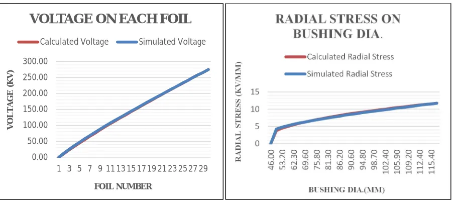
Figure 4 shows the proposed design 2D view in which no .of foils are reduced. All these graph results shown below states that the calculated voltage distribution and radial stress values are exactly matching with the results of voltage distribution and radial stresses given after simulation by ElecNet which also shows that my results are holds good and very accurate.
Figure 4: 2D view of proposed design
V. SIMULATION RESULTS
[image:6.612.83.534.466.665.2]A. Existing Design graphs of result are shown below
Figure 5: Voltage Distribution and Radial Stress variation in the Bushing and with respect to foil number
0.00 50.00 100.00 150.00 200.00 250.00 300.00
1 3 5 7 9 11 13 15 1719 21 23 2527 29
V O LTA G E (K V ) FOIL NUMBER
VOLTAGE ON EACH FOIL
Calculated Voltage Simulated Voltage
0 5 10 15 4 6 .0 0 5 3 .2 0 6 2 .3 0 6 9 .6 0 7 5 .8 0 8 1 .3 0 8 6 .2 0 9 0 .6 0 9 4 .8 0 9 8 .7 0 1 0 2 .4 0 1 0 5 .9 0 1 0 9 .2 0 1 1 2 .4 0 1 1 5 .4 0 R A D IA L S TR ES S (K V /M M ) BUSHING DIA.(MM)
RADIAL STRESS ON
BUSHING DIA
.
Calculated Radial Stress
Simulated Radial Stress
Foil No Calculated Voltage(kV)
1 0
Technology (IJRASET)
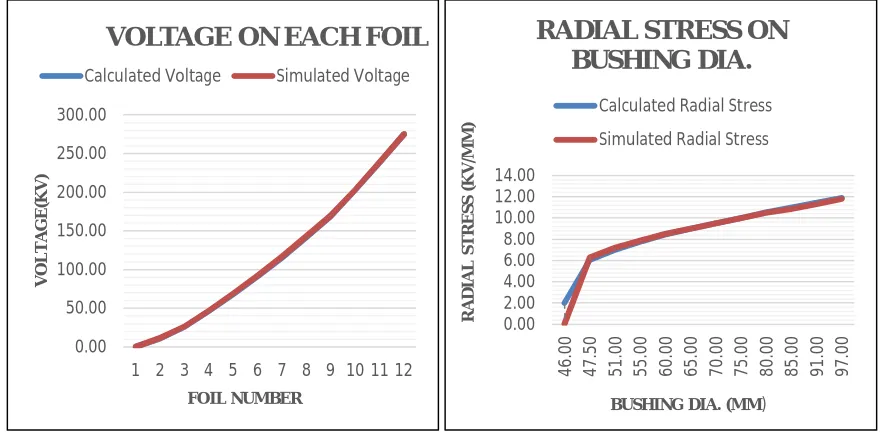
[image:7.612.85.528.100.318.2]B. Proposed design graphs of result are shown below
Figure 6: Voltage Distribution and Radial Stress variation in the Bushing and with respect to foil number
The diagram shown below gives the results of electrostatic stresses on existing and proposed design of 145kV current transformer. In which the stresses on the proposed bushing design are comparatively reduced with respect to the existing design.
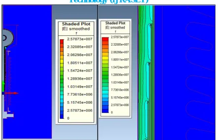
Figure 7:2D Electric Field Plot of CT model under dry high voltage power frequency condition on Existing desi
0.00 50.00 100.00 150.00 200.00 250.00 300.00
1 2 3 4 5 6 7 8 9 10 11 12
V O LTA G E(K V ) FOIL NUMBER
VOLTAGE ON EACH FOIL
Calculated Voltage Simulated Voltage
0.00 2.00 4.00 6.00 8.00 10.00 12.00 14.00 4 6 .0 0 4 7 .5 0 5 1 .0 0 5 5 .0 0 6 0 .0 0 6 5 .0 0 7 0 .0 0 7 5 .0 0 8 0 .0 0 8 5 .0 0 9 1 .0 0 9 7 .0 0 R A D IA L S TR ES S (K V /M M )
BUSHING DIA. (MM)
RADIAL STRESS ON
BUSHING DIA.
Calculated Radial Stress
Technology (IJRASET)
Figure 8: 2D Electric Field Plot of CT model under dry high voltage power frequency condition on Proposed design
VI. CONCLUSION
This paper presents the new insulation scheme of capacitive graded bushing for 145kV current transformer. Simulation result shows that the complete Electrical stress and voltage (contour) plot of the existing design and proposed design of condenser bushing has same radial stress along the bushing diameter & between the foils and axial stress is also under the limit. Moreover the voltage distribution on each electrode or each aluminum foil is giving the same result as compared with the practical or theoretical calculations. The major benefit of this FEM method is that minimum/maximum stress in any zone/material can be calculated very precisely & resulting in better understanding of electrostatic stress distribution, optimization & higher technical reliability. Exact stress analysis in the critical locations under the dry power frequency high voltage is done and this analysis clearly shows that the stress value in the critical regions is well below the limit compared with the existing design.
REFERENCES
[1] V. Smekalov, “Bushing insulation monitoring in the course of operation”, Transaction in CIGRE proceedings, 12-106, 1996.
[2] S. D. Kassihin, S.D. Lizunov, G.R. Lipstein, A.K. Lokhanin, and T. I. Morozova, “Service experience and reasons of bushing failures of EHV transformers and
shunt reactors”, Trans. CIGRE proceedings, pp. 12- 105, 1996.
[3] Amin Mahmoudi, Seyed Mahdi Moosavian, Solmaz Kahourzade1 and Seyed Nabi Hashemi Ghir‘‘Capacitor bushing optimization via electrostatic finite
element analysis” in International Journal of the Physical Sciences Vol. 7(2), pp. 306 - 316, 9 January, 2012.
[4] Mohammad R. Hesamzadeh, Nasser Hosseinzadeh and Peter Wolfs‘‘An Advanced Optimal Approach for High Voltage AC Bushing Design” in IEEE
Transactions on Dielectrics and Electrical Insulation Vol. 15, No. 2; April 2008.
[5] Haoran Wang, Zongren Peng, Shiling Zhang, Peng Liu ‘‘Simulation study of edge effect in high voltage Condenser bushing foils” in 2013 IEEE International
Conference on Solid Dielectrics, Bologna, Italy, June 30 – July 4,2013.
[6] G.Lalwani*, R.K.Singh, S.K.Gupta, J.S. Kuntia, R.K.Tiwari‘‘Electrostatic field analysis of 1200 kV testing Transformer by boundary element method” in
Proceedings of the 16th International Symposium on High Voltage Engineering Copyright °c 2009 SAIEE, Innes House, Johannesburg.
[7] Y. 8ulent Yildir “Computer-aided Field Analysis of High Voltage Apparatus using the Boundary Element Method" in Proceedings of the International Coil
Winding Conference, Ro.Empat. U Iooe, October S4 Im.
![Figure 2, radially and axially. These two stresses have a very vital and crucial role while designing the bushing configuration and thus designer or engineer should try to keep it in the acceptable limit while designing [2], so as to have the uniform and m](https://thumb-us.123doks.com/thumbv2/123dok_us/8580041.860592/4.612.189.422.379.480/radially-stresses-designing-configuration-designer-engineer-acceptable-designing.webp)