Technology (IJRASET)
CFD Analysis of Air and Steam in a Rectangular
Channel Having Parallel RIBS
S. Srinivasan 1, A.U. Jeevan Kumar 2
Mechanical Engineering, Velammal Institute of Technology
Abstract: A Computational fluid dynamics analysis of air and steam cooling a rectangular channel with parallel ribs. The effects
of Reynolds numbers (Re), rib spacing ratio (P/e), and rib angles (α) on steam and air convective heat transfer were obtained.
Heat transfer distribution is done for rib spacing ratio (P/e)=8, 10 and 12 and ribs angle 900 to 450.The heat transfer enhancement of both air and steam increased with decreasing the rib angle from 90° to 45° . Although both air and steam flow are similar to each other, the steam flow obtains a high convective heat transfer enhancement capability. For the corresponding degrees the heat transfer coefficient decreases and a study is made on rectangular duct having acute and right angled ribs based on a backflow. Study is made on P/e = 8 having higher strength when compared with P/e = 12 is analyzed based on heat transfer of air and steam flow through a rectangular duct. The modelling has be done on the Creo parametric 2.0 software and to get the exact mesh of the duct the meshing was done in Hypermesh and the analysis were done in CFD Fluent software.
Keywords: Turbulant, boundary conditions ,spacing ratio inclination, Ansys(CFD fluent);
I. INTRODUCTION
Improving the turbine inlet temperature is an effective measure to promote the thermal efficiency and output power of gas turbines. The inlet temperature of modern gas turbines has been far higher than the heat-resistant limit of turbine materials. Therefore, studies on the high-performance turbine cooling technology have been the hotspot in the gas turbine field, including film cooling, rib roughened cooling, impingement cooling, and transpiration cooling Among them, the rib roughened cooling technique with its small pressure loss and simple structure has been widely applied in the design of cooling chamber in the middle- section of the turbine blade. Thus, it has gained wide attention in the studies of traditional air cooling The heat transfer performance of parallel ribs in channels with circular cross section were studied. The influences of different rib angles, rib spacing and rib height on the heat transfer performance have been studied. In case of given P/e, friction factor and heat transfer coefficient increase with the increase of e/D. In case of given e/D, friction factor and heat transfer coefficient decrease with the increase of P/e. The heat-transfer characteristics of 45 o inclined rib in square cooling channel with Width/Height of 1:4 and 1:2 in rotation state are studied. It was found that in the square cooling channel with low Width/Height, the heat transfer enhancement of 45o inclined rib in stationary state is about 2.5–3 times of smooth channel. We proposed one optimized method for designing parallel rib turbulators. Through adjusting the ratio of rib height to channel equivalent diameter (e/Dh = 0.118–0.353) and the ratio of rib spacing to height (P/e = 5– 10), the optimized design of rib turbulator can be realized. It has been determined that in static ribbed channels the heat transfer performance mainly depends on Width/Height, fin shaped, Reynolds number and the heat transfer enhancement mechanism of ribs caused by air isolation has been known through various experiments. The heat transfer of 90 o ribbed channel (square W/H = 1 and rectangle W/H = 2, 4) with rib spacing (P/e = 10, 20). It indicated that the local Nusselt number of the smooth side obviously decreases along the flow direction and the air in the channel periodically isolates from the rib and the reattachment on the wall leads to the Nusselt number’s period distribution of the ribbed side. We adopted transient liquid-crystal technology to measure the heat transfer coefficient distribution in the smooth and 180 o turning channel. At the turning, Nusselt number increases and the highest Nusselt number occurred at the external wall far from the separator. After turning, the air reattaches on the wall, which transmits the enhancement and non-uniform effects of the turning on heat transfer to further. Besides, we also made many fundamental researches on the ribbed cooling technology.
Technology (IJRASET)
component of gas turbine. Steam comes from steam turbine in Integrated Gasification Combined Cycle (IGCC) and after it cools the high-temperature components of gas turbine. Finally, it returns to the steam turbine for cycle. The cooling medium does not mix with main flow. Usually, this kind of the cooling system is called closed-loop steam cooling system. Compared with the conventional air cooling technology, steam is taken as cooling medium, which not only can substantially decrease the air-entrainment in compressor but also eliminates the pressure loss generated by the mixing of air and main flow. Therefore, the performance of the whole circulation system can be greatly improved. To break through the bottleneck of the traditional blade cooling technology and develop the next-generation high-performance gas turbine, the application of steam cooling technology in high-temperature turbine blade has been the research focus and hotspot of heavy-duty gas turbine cooling technology. The basic design strategy of steam cooling gas turbine, Facchini analyzed the advantages of the closed-loop cooling technology for double mediums (air and steam) and its contribution to the system efficiency. The research results indicated that the cooling efficiency of the closed-loop steam cooling blade can be significantly improved at the same combustion temperature compared with air cooling blade. The efficiency of the combined cycle power station can be improved by 1.5%.The cooling performances for air and steam flow is studied and their results indicated that in the selected model, steam, as the cooling medium, can significantly improve the cooling efficiency of the leading edge and central areas of the blade. The comparative study carried out on a cooling performance of open-loop air cooling system, open-loop steam cooling system and closed-loop steam cooling system. Results indicated that the output power of the closed-loop system in the steam cooling mode can be improved by 11% compared with air cooling and the efficiency can be improved by 3.2%. Study has been made on the steam cooling performance of one turbine blade respectively by experimental and numerical methods. The study results indicated that steam cooling can completely satisfy requirements instead of air cooling.
The experimental study on the heat transfer characteristics of steam cooling in inclined ribbed channel. They found that under their studied Reynolds number (Re), the area-averaged Nusselt number (Nu) of 45o ribbed channel is about 15–25% higher than that of 60o. They compared the heat transfer between steam and air flow in a square duct. They found that the Nusselt number of steam is about 12–25% higher than that of air under the same operating condition. The numerical analysis was made to study the influence of rotation on the steam cooling characteristics in 45o ribbed channel and rotation can lead to the fluid enhanced turbulence and the anisotropy of Reynolds stress in the cooling channel, which has significant influences on the distribution of the local Nusselt number of the channel wall.
Hiyama et al., presented their project for the development of component technology for the next generation 1700o C J-class gas turbine, from the report we know that closed steam cooling design is also adopted for combustor hardware, which is based on the experienced G-series design. So, steam cooling technology is very important for designing future gas turbine as well as air cooling technology.
In this project, fluent was used to investigate the distribution of the forced convection heat transfer coefficients in a rectangular channel cooled by superheated steam and air. Parallel ribs were set into the channel, and the influence of Reynolds number (Re = 3000–15,000), the rib spacing ratio (P/e = 8, 10, 12) and rib angle(a = 90o, 75o, 60o, 45o) on heat transfer of rib roughened channels were investigated. To explore the superiority of heat transfer for steam cooling to air cooling in rib-roughened channels, the local and area-averaged Nusselt numbers for the two coolants were compared with each other.
II. THEORY
A. Computational Fluid Dynamics
1) What is CFD?: Computational fluid dynamics or CFD is the analysis of systems involving fluid flow, heat transfer and associated phenomena such as chemical reaction by means of computer-based simulation. The technique is very powerful and spans a wide range of industrial and non-industrial application areas.
2) How does CFD code work?: CFD codes are structured around the numerical algorithms that can tackle fluid flow problems. In order to provide easy access to their solving power all commercial CFD packages include sophisticated user interfaces to input problem parameter and to examine the results. Hence all codes contain three main elements: Pre-processor, Solver & Post-processor
a) Pre-processor: Pre-processing consists of the input of a flow problem to a CFD program by means of an operator-friendly interface and the subsequent transformation of this input into a form suitable for use by the solver.
Technology (IJRASET)
b) Solver: There are three distinct streams of numerical solution techniques: finite difference, finite element and spectral methods. Approximation of the unknown flow variables by means of simple functions. Discretization by substitution of the approximations into the governing flow equations and subsequent mathematical manipulations. Solution of the algebraic equations.
i. Finite difference method: Finite difference methods describe the unknowns φ of the flow problem by means of point samples at
the node points of a grid of co-ordinate lines.
ii. Finite elemet method: Finite elements use simple piecewise functions eg,(linear or quadratic ) valid on elements to describe the local variationa of unknown flow variables. The governing equations is precisely satisfied by the exact solution.
iii. Spectral methods: Spectral methods approximate the unknowns by means of truncated fourier series or series of chebyshev polynomials. Unlike the finite difference or finiteelement approach the approximations are not local but valid throughout the entire computational domain.
iv. The finite volume method: The finite volume method was originally developed as a special finite difference formulation. This shall be solely concerned with this most will established and thoroughly validated general purpose CFD technique.it is central to four of five main commercially available CFD codes; PHOENICS,FLUENT, FLOW 3D and STAR 3D.
c) Post-processor: As in preprocessing huge amount of development work has recently taken place in the post-processing field. Owing to the increased popularity of engineering workstations many of which have outstanding graphics capabilities, the leading CFD packages now equipped with versatile data visualization tools. These includes
i. domain geometry and grid display
ii. vector plots
iii. line and shaded contour plots
iv. 2d and 3d plots
v. particle tracking
vi. view manipulation
[image:4.612.188.433.419.693.2]vii. colour postscript output
Technology (IJRASET)
Figure II.2 outlet boundary condition
III.CFDCALCULATION
A.CFDFORMULAE
1) Energy equation
Ə/Ət(ρE)+ Δ( (ρE+ρ))= Δ(keff ΔT)+Sh ...1.2
The volume of finite model treats energy E and t temperature T as mass
2) Averaged variables
E= Σn q=1 αqρqEq/ Σn q=1 αqρq ………….1.3
3) Momentum equation
Ə/Ət(ρ )+ Δ(ρ )=- Δp+ Δ[µ(Δ + T)]+ ρ
4) Standard k-omega model
Ə/Ət(ρk)+ Ə/Əxi (ρkui)= Ə/Əxj(Γ Ək/ Əxi)+Gk–Yk+Sk .………1.5
and
Ə/Ət(ρw)+ Ə/Əxj(ρwui)= Ə/Əxj(Γw Ək/ Əxi)+ Gw–Yw+Sw ……….1.6
5) Continuity equation
Technology (IJRASET)
6) Momentum conservation equation
Ə/Ət(ρ )+ Δ(ρ )= Δp+ Δ( − )+ρ+ ……….1.8
7) Area weight average
1/A∫ ΦdA=1/A ∑ =1 Φi|Ai| ……….1.9
8) Vertex Maximum
The vertex maximum of a specified field variable on a surface is the maximum vertex value of the selected variable on the surface.
9) Vertex Minimum: The vertex minimum of a specified field variable on a surface is the minimum vertex value of the selected variable on the surface.
10) Hypermesh: Most FEA and CFD software do not have a great meshing algorithm; even when they have it, they do not allow good manual control on the mesh. The result is that after meshing a complicated geometry the mesh is lacking in quality, which means the analysis would either fail or give less than accurate answers. Additionally some elements like beams, pretension, are not easily created in FEM software. Hence a requirement of a good Finite Element (or Finite Volume in case of CFD) software is sometimes felt, especially in dealing with castings or large assemblies. HyperMesh made by Altair Inc. is the most popular software in this regard. However this is gradually falling out of favor in most OEMs as newer versions of solvers pack better meshing algorithms and thus reduce the time spent on the software and the investment on a package and training of the analyst. Newer packages are designed so as to help the designer himself perform the analysis and thus shave time off the product development cycle. This may not be the case however in a high Fidelity analysis in an aerospace or similar environment where speed is secondary and accuracy primary.
IV.LITERATURESURVEY
Ahmed M et al Faculty of Engineering , Jazan University, Jazan Numerical study of turbulent periodic flow and heat transfer in a square channel with different ribs, Saudi Arabia presented many experimental and numerical investigation were carried out to determine the configuration that produce optimum results in terms of both heat transfer and pressure loss.
Giovanni Tanda ,et al of DITEC, University of Genoa presented has the heat transfer coefficient measurements in ribbed channels using liquid crystal thermography and concluded that :
The inter-rib distributions of the heat transfer coefficient are strongly related to rib shape and geometry.A relative maximum is typically attained downstream each rib for continuous transverse ribs(due to flow reattached),45 deg shaped ribs and 60 deg V-shaped ribs at p/e=13.3
Shailesh Gupta, et al has explained the augmented heat transfer in square ducts with transverse and inclined ribs with and without a gap and conclusion are followed that:The experimental investigation has been performed for the continuous ribs (with no gap) and ribs with a gap having relative roughness pitch (p/e) of 10,relative roughness height (e/Dh ) of 0.060 and rib attack angle of 90o and 60o for Reynolds number from 5000 to 40,000.Thermal efficiency and power output of gas turbines increase with increasing turbines Rotor Inlet Temperature (RIT).
V. EXPERIMENTALSETUP
A. The test rig
Technology (IJRASET)
[image:7.612.191.404.237.338.2]Figure IV.1 Smooth channel without ribs in creo
Figure IV.2 Channel with ribs in creo
Figure IV.3 spacing_600
where Rec is used to record user defined voice and del is used to delete the recorded voice and pla
y is used to play the recorded voice.
During recording voice Rec pin is enabled and any one of the analog pins from 5 pins is enabled(For Ex.A0 pin). The user is made to speak and that analog pin is disabled so that the spoken voice is stored in that pin, likewise 5 pins are stored with different voices. During playing Rec is disabled and Play is enabled with any one of the analog pin so that stored voice in that corresponding pin is played. When it is to be done automatically by controller the condition is fixed while
VI.RESULTSANDDISCUSSION
A. Local heat transfer characteristics
[image:7.612.185.420.388.494.2]Technology (IJRASET)
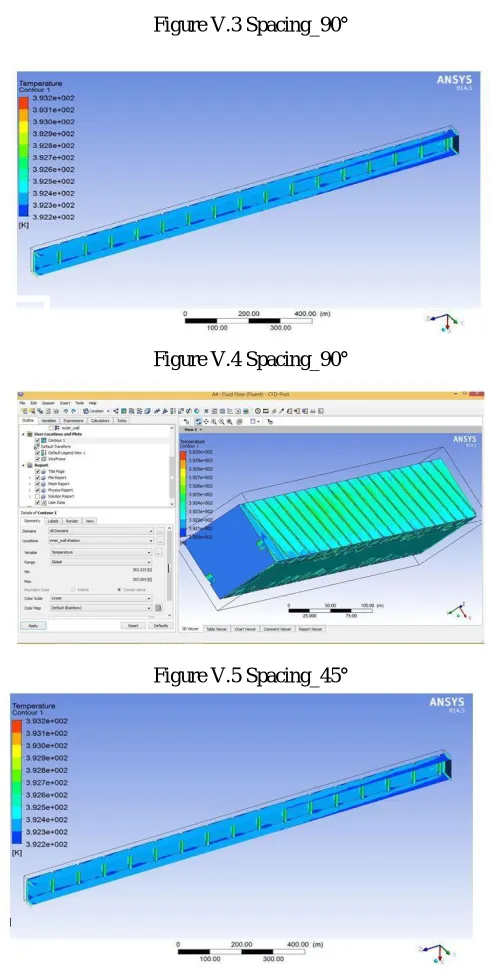
If the thermal picture of the entire heat transfer surface is captured in the experiment, the CFD fluent must be adjusted to a high elevation from the tested surface because of the small view angle. Nevertheless, the investigations conducted by Han showed that periodic fully developed regions of the Nusselt number would be formed behind the second or third rib turbulator when air flows through a row of ribs. As a consequence, the CFD fluent only needs to focus on the area behind the first two ribs along the mainstream direction in our experiment to measure the heat transfer in a fully developed turbulence state. For channels with rib turbulators cooled by steam and air, the repeated characteristics of the distributions of heat transfer starting from the third rib. By contrast, a fully developed Nusselt number takes a long downstream distance for a smooth surface. At the same condition, the distributions of heat transfer characteristics for steam cooling and air cooling are similar to each other, whereas the heat transfer enhancement for steam is more intense than that for air.
The results on the 90° rib roughened surface with P/e = 12 indicate that strong heat transfer areas are developed in the middle of the inter-rib regions, and this finding can be ascribed to the flow reattachment in this region. By contrast, the regions with low Nusselt number near the ribs (both in front of and behind the ribs) can be observed. The generation of the two weak heat transfer regions can be attributed to the following reasons. First, the turbulent flow caused by the rib turbulator in the region in the rear of the rib results in a low-pressure area, and a part of the reattachment of flow flows back to this area. A high-pressure area is generated in the region in front of the rib, and the separation occurs when the reattaching flow moves past the following rib. These two different processes would form vortexes, and the flow recirculation zone occurs in front of and behind the ribs. This phenomenon that could explain the inferior formation mechanism of the heat transfer characteristics. In addition, the regions close to the side-walls achieve good heat transfer performance as a result of the strong secondary flow generated by the interference of turbulence. This interference is induced by the rib turbulators and the viscous force near the walls.
[image:8.612.221.429.411.715.2]For 90o rib roughened channels with smaller rib spacing ratios (P/e = 10 and 8), the scopes of high heat transfer areas remains approximately the same due to the similar effects provided by the reattachment of coolant as well as the interference generated by the ribs and walls in P/e = 12 channel. In contrast to the little change of the weak heat transfer region behind the rib, an obvious decrease in low heat transfer area in front of the rib can be noticed with gradually decreasing the inter-rib pitches and the area nearly disappears when the rib pitch equals 8e. The reason of the phenomenon is that the relative position of the flow reattachment point to the following rib approaches closer for a lower rib pitch, area of the flow dead zone in front of the rib also decreases.
Figure V.1 Spacing_90°
Technology (IJRASET)
Figure V.3 Spacing_90°
Figure V.4 Spacing_90°
Figure V.5 Spacing_45°
Technology (IJRASET)
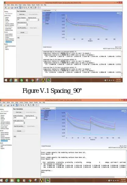
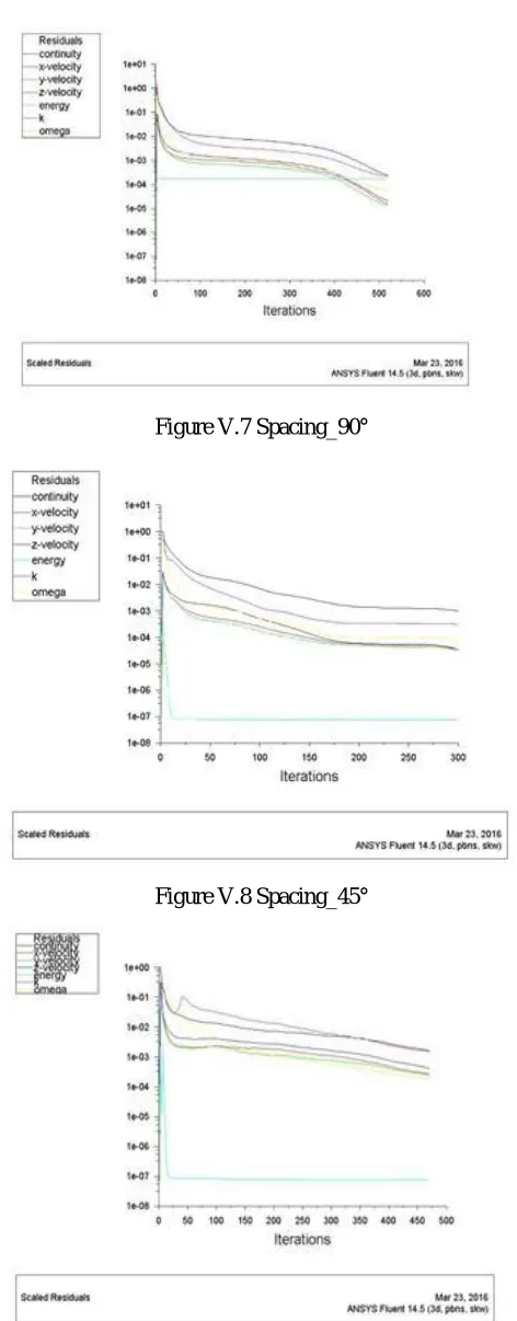
[image:10.612.187.423.89.692.2]B. Air Residuals Graph
Figure V.7 Spacing_90°
Figure V.8 Spacing_45°
Technology (IJRASET)
VII. ADVANTAGES
A. To find out the maximum cooling rate in similar duct
B. To reduction in material of duct
C. To convert sub laminar flow to turbulence which is high cooling rate
D. To increase the strength of duct
E. The thermal conductivity of material changes comparative study leads to high understanding duct . Limitations: Cost of pipelining is high
VIII. CONCLUSION
The heat transfer characteristics of steam and air flow in a rib roughened channel with various rib spacing ratios (P/e = 8, 10 and 12) and rib angles (a = 90o, 75o, 60o and 45o) are experimentally investigated. Nusselt number distributions are obtained on the heat transfer surface of the rib roughness channels with using an CFD fluent. The main conclusions of this study are summarized as follows:
A. The heat transfer distributions of steam and air flow in the rib roughness channel are similar to each other. For the 90 o rib roughened channel, the area with low heat transfer is located before and behind the rib turbulators, whereas the area with high heat transfer mostly exists in the middle region between the ribs. Rib spacing ratio (P/e) has a relative weaker effect on heat transfer enhancement.
B. Angled rib turbulators positively affect the heat transfer enhancements for both steam and air flow. A significant heat transfer enhancement is achieved in the region close to the upwind side of the rib turbulators. However, the Nusselt number values decrease along the rib pointing direction.
C. Rib angles significantly affect Nusselt number distribution and distinctively affect area-averaged heat transfer. The average Nusselt numbers for steam and air increase with a decrease in rib angle from 90 o to 45 o. The greatest heat transfer coefficients for the two coolants are obtained in the 45 o rib roughened channel in the present investigation.
REFERENCES
[1] Ahmed M. Bagabir, Jabril A. Khamaj, Ahmed S. Hassan. (2013) ‘Numerical study of turbulent periodic flow and heat transfer in a square channel with different ribs’ Journal of applied mathematics and physics, 65-73.
[2] Shailesh gupta, Alok chaube and Prakash verma. (2013) ‘Augmented heat transfer in square ducts with transverse and inclined ribs with and without gap’ International journal of current engineering and technology ISSN 2277 – 4106
[3] K.Sivakumar, Dr. E.Natarajan and Dr. N.Kulasekharan. (2014) ‘Heat transfer and pressure drop comparison between smooth and different sized rib-roughened rectangular divergent duct’ International journal of engineering and technology(IJET), ISSN : 0975-4024, Volume 6.
[4] M Alhajeri and H. Alhamad Alhajeri. (2009) ‘Heat and fluid flow analysis in gas turbine blade cooling passages with semicircular turbulators’ International journal of physical sciences. Volume 4 (12), pp. 835-845.
[5] S. W. Ahn, M.S. Lee. (2014) ‘Turbulent flow and Heat transfer in the ribbed divergent channel’, International conference on heat transfer and fluid flow prague, Czech republic, August 11-12.
[6] Oronzio Manca, Serigo Nardini, (2011) ‘Daniel Ricci. Numerical Study of Air forced convection in a channel provided with inclined ribs’ Frontiers in Heat and mass transfer (FHMT), 2, and 013007.
[7] Anand Shukla, Alok chaube, Shailesh gupta and Arvind sirsath, (2014) ‘Experimental investigation of heat transfer and friction factor characteristics of a stationary square duct roughened by V and A-Shaped ribs’ Frontiers in Heat and Mass transfer (FHMT).
[8] Nawaf Yahya Alkhamis, B.Sc king Abdulaziz University (August 2009) ‘Heat transfer and pressure drop measurement for square channels with V-shape ribs at high Reynolds Numbers’.
[9] Umesh potdar, Nilesh Shinde, and Manoj Hambarde, (2012) ‘Study of heat transfer coefficient and friction factor of stationary square channel with V shaped and 450 angled arc of circle ribs with different blokage ratio’ Int. Journal of applied science and engineering research, Volume 1, No. 2, ISSN 2277-9442.
[10] Kesavulu.P, Jaya Kishore.S, V.Gnana Prakash, (August 2015) ‘Thermal Analysis of internal cooling in Turbine blade’ International Journal for technological research in engineering, volume 2, issue 12, ISSN (online) : 2347-4718.
[11] Priyanka singh, O P Shukla, (july 2015) ‘Heat transfer analysis of Gas turbine rotor blade cooling through staggered holes using CFD’ ISSN: 2278-0181. [12] Priyank Lohiya, Shree Krishna Choudhary, ‘Numerical study on heat transfer of turbulent duct flow through ribbed duct’ International journal of engineering
sciences & research technology, ISSN : 2277-9655.
[13] Rahul saikedhkar and S.S.pawar, (2014) ‘Heat transfer enhancement through a rectangular duct’ Corona journal of science and technology, ISSN: 2319-6327(online) Volume 3, No. III
[14] Sandeep kumar karole, Ishwar singh, Pankaj sonkusre, (March 2015) ‘Heat transfer and friction behaviors in rectangular duct with two different ribs’ IJSTE volume 1, Issue 9, ISSN (online): 2349-784X.
[15] Sohil Akhter, Ishwar singh, ‘Turbulent heat transfer and pressure drop in an internally ribbed Rectangular duct’ IJETCAS paper ISSN (online): 2279-0055. [16] ‘Fluid Mechanics’ by Frank M White, Mc Graw-Hill Edition, 2011.