FUZZY LOGIC BASED PV ENERGY SYSTEM WITH SEPIC
CONVERTER
1S.VENKATANARAYANAN, 2M.SARAVANAN
1Assoc Prof., Department of Electrical Engineering, K.L.N.College of Engineering Sivagangai, INDIA
2
Prof., Department of Electrical Engineering, Thiagarajar College of Engineering, Madurai, INDIA
E-mail: [email protected], [email protected]
ABSTRACT
This paper is to present the Fuzzy Logic based sand –alone solar Photovoltaic (PV) system with the isolated SEPIC converter. The system is designed for 750W solar PV panel and to feed an average demand of 250 W. This system includes solar panels, MPPT (Maximum Power Point Tracking) controller, a SEPIC converter, an energy storage system and a single phase VSI (Voltage source inverter). The SEPIC converter provides a constant DC bus voltage and its duty cycle controlled by the MPPT controller which is needed to improve PV panel’s utilization efficiency. A fuzzy logic controller (FLC) is used to generate the PWM signal for the SEPIC converter to extract maximum power. Simulated using MATLAB SIMULINK, results are presented to demonstrate the performance of the MPPT controller for various load conditions.
Keywords: PV Energy System, Isolated SEPIC Converter, Fuzzy Logic Controller, Voltage Source
Inverter. Introduction
1. INTRODUCTION
Increasing energy demand and environmental issues over the fossil fuels have significantly developed interest in green energy sources to replace the fossil fuel. The PV power systems are gaining popularity more than other renewable sources because of their ease of installation, less maintenance and isolated mode of power generation and are proven to be effective solution for feeding energy demand of rural areas.
A SEPIC converter is used to provide a constant dc bus voltage and duty cycle has been controlled by the MPPT controller. The modified incremental conductance approach has been utilized for MPPT. In this approach, MPPT controller has automatically generated a PWM signal for the SEPIC converter to extract maximum power [1]. A posicast control based on feedback structure has been designed and implemented to eliminate the peak overshoot on the output voltage of the SEPIC converter to improve the settling time and to reduce
the sensitivity of classical feed forward Posicast control [2].A two loop digital control strategy has been proposed for the two input integrated converter, and then, the optimal power distribution has been realized on the input dc sources.
This can be achieved by using two decoupled digital controller, one for load voltage regulation and another for LVS current control [3]. A low power stand-alone solar –PV energy generation system with a SEPIC converter has been designed. The performance analysis of the system has been presented under the variation in solar radiations with the device current and voltages[4].Single switch cell voltage equalizers by using multi staked buck-boost converter for series connected energy storage cell has been used[5].
developed in this work. A fuzzy logic controller generates the PWM signal for the SEPIC converter to extract maximum power. The system is designed with 750W solar panel and to feed the an average load demand of 250W.The excess energy obtained from the PV generating system of after meeting the load demand is stored in a battery storage system. The SEPIC converter with MPPT controller is needed to improve PV panel efficiency and matches the load to the photovoltaic module.
1.1 System Details And Design Consideration
Solar-PV cell produce electricity directly by controlling the solar energy in to electrical energy. The output voltage and current of the single PV cell is quite small to be used practically and the PV cells are used in serial and parallel combinations, called PV array and is used to produce significant level of voltage and current. In this work the solar PV energy generation system is designed to feed an average load of 250W.By considering this load, the rating is selected for solar PV panel is 750W. For utilization of energy produced by the 750W solar PV system, an energy storage system, which can store the surplus energy and delivering it to the load, is used. The standard panels are connected in series –parallel combination to realize 750W rated power system. The specification of the selected configuration is given in table. Fig.1. shows the system composition with the MPPT controller. This system consists of solar PV panel, an isolated SEPIC converter, energy storage system, a VSI and a low pass filter to feed consumer loads.
Fig.1 System Composition With MPPT Controller
The variable dc voltage of the PV panel is converted to a constant dc voltage using a SEPIC converter. The output of PV array is boosted to 380V to provide a constant dc link for the battery charging. The SEPIC Converter is controlled by a
MPPT approach to ensure maximum energy capture. A VSI converts the dc voltage of the battery to a 230V, 50Hz to feed ac consumer loads. To ensure the good power quality for the consumers, the VSI is used with the filter and its control loops, which regulates the output voltage and current by controlling the duty ratio of the VSI switches.
A. Design Of Pv Array
The PV system directly converts sunlight into electricity. A SEPIC converter is to process the electricity from the PV system. These converters either increase or decrease the PV system voltage at the load. The proposed SEPIC converter operates in boost mode.
Fig.2 Equivalent Circuit Of A Pvcell
The practical equivalent circuit of a PV module is shown in fig 2. and its typical output characteristics are shown in fig 3. In the equivalent circuit, the current source represents the current generated by the light photons and its output is constant under constant temperature and constant irradiance. The diode shunted with the current source determines the I-V characteristics of PV module. Here the resistance in series with the current path through the semiconductor material, the metal grid, contacts, and a current collecting bus are lumped together as a series resistor (Rs). Its effect becomes very noteworthy in PV module. The loss associated with a small leakage of current through a resistive path in parallel with intrinsic device is represented by a parallel resistor (Rp). Its effect is much less noteworthy in a PV module compared to the series resistance and it will only become noticeable when a number of PV modules are connected in parallel for a larger system.
(
)
−
+
−
=
V
I
R
1
ART
q
exp
I
I
I
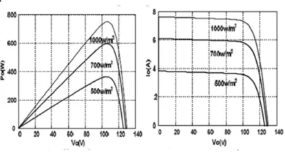
pv ph r pv pv s (1)where Ipv is the output current from the PV array, Vpv is the output voltage of the PV array, Iph is the photo generated current of the PV cell, Ir is the reverse saturation current of the diode, q is the electronic charge, A is the ideality factor, K is the Boltzman constant, T is the operating temperature of the cell and Rs is the internal resistance of the cell. From the Eq.(1) the PV cell is modeled in Simulink. As seen in the power versus voltage curve of the module shown in the Fig.3,there is a single maximum of power and there exists a peak power corresponding to a particular voltage and current
[image:3.612.91.298.311.423.2].
Fig. 3 PV Module Characteristics
Since the module efficiency is low it is desirable to operate the module at the peak power point so that the maximum power can be delivered to the load under varying temperature and insolation conditions. Hence maximization of power improves the utilization of the solar PV module. A maximum power point tracker (MPPT) is used for extracting the maximum power from the solar PV module and transfers it to the load.
B. Mppt Control Algorithm
A PV array is a nonlinear power source, which under constant uniform irradiance has a current-voltage(I-V) characteristic like that shown in Fig 3. There is a unique point of the curve, called the maximum power point(MPP), at which the array operates with maximum efficiency and produces maximum output power.
Table I: Pv Module Specifications
Electrical characteristics Value Maximum Power(Pmax) 750W
Voltage at Pmax(Vmp) 106.5V
current at Pmax(Imp) 7.04A
Open circuit voltage(Voc) 129.63V Short circuit current(Isc) 7.63A
So it is necessary to constantly track the MPP of the solar array. A switch-mode power converter
(SEPIC) called a Maximum Power Point
Tracker(MPPT), can be used to maintain the PV array’s operating point at the MPP.
There are various techniques used for tracking
maximum power like P&O, Incremental
Conductance(IC) and fuzzy logic control(FLC). Among these algorithms FLC is equipped in this work. FLC has the advantage of an easy implementation and it does not need any accurate mathematical model of the system and it is very suitable for non linear system. It work under intelligent control method. In FLC the given crisp set values are converted into linguistic variables by using fuzzification unit. The reference value is decided and according to the actual value of the voltage and power the error value is calculated. By using this error value the change in error value is calculated. The two FLC input Variables are the error E and change of error CE at sampled times k
( )
( ) (
( ) (
)
)
( ) ( ) (
)
−
−
=
−
−
−
−
=
1
k
E
k
E
k
CE
1
k
V
k
V
1
k
P
k
P
k
E
(2)inference is carried out by using Mamdani’s method and the defuzzification uses the centre of gravity to compute the output of this FLC which is the duty cycle
( )
( )
∑
∑
− =
−
=
nj
j n
j
j j
d
d
d
d
1 1
α
µ
α
α
α (3)
The control rules are indicated in table 2 with E and CE as inputs and dα as the output.
[image:4.612.118.265.338.431.2]In the defuzzification, the output is converted from a linguistic variable to a numerical crisp one again using membership functions.
Table II : Fuzzy Rule Table
The membership function for error(E), change in error(CE) and output for shown.
Fig. 4 Membership Function
There are different methods to transform the linguistic variables into crisp values. It can be said that the most popular is the center of gravity method.
C. 2. SEPIC CONVERTER
The important requirement of any DC– DC converter used in the MPPT scheme is that it should have a low input-current ripple. Buck converters will produce ripples on the PV module side currents and thus require a larger value of input capacitance on the module side. On the other hand, boost converters will present low ripple on the PV module side, but the load current exhibits more ripple and gives a voltage higher than the array voltage to the loads.
The buck– boost converters can be used where the requirement of load voltage, either low or higher than the array voltage. However, with this converter the input and load currents are pulsating in nature. Furthermore, the load voltage will be inverted with buck–boost or CUK converters. Under these conditions, the SEPIC converter, provide the buck–boost conversion function without polarity reversal, in addition to the low ripple current on the source and load sides.
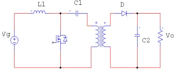
The SEPIC(Single Ended Primary
[image:4.612.326.506.430.506.2]Inductance Converter) topology with isolation is proposed and the converter is operated in continuous Current Mode(CCM) and the converter is operated in boost conversion.
Fig.5 Isolated SEPIC Topology
The converter has input inductance L1 and input capacitance C1 has the values of 1.27mH and 111.3µF. The isolation transformer has the winding ratio of 1:5. The output capacitance has the value of 22.4µF. The duty cycle D can be determined from the steady state conduction and the equation can be written as
D
D
N
N
V
V
in c
−
=
1
1 2
[image:4.612.95.293.481.633.2]3. DESCRIPTION OF WORKING
The variable dc voltage of the PV panel is converted to a constant dc voltage using a SEPIC converter. The Maximum power output is product of Vmp and Imp. According to this the output power ranging at 750W. The irradiation level should be 500W/m2 at 0.1s and 900W/m2 at 0.2s. The maximum power output is depends on the solar irradiation level. Upto 0.1s the voltage should be around 110V and the current should be near 3.5A.The maximum power should be 380W. From 0.1s to 0.2s the current level should be increased to the value of 4A. The power output should be increased to 700W. To obtain the Maximum power at any insolation the MPPT algorithms are used. Here FLC is proposed.
In the Fuzzy Logic Controller there are two inputs namely error and error_rate. The error_rate should be the value of 106V as a set value and the error should be from the controller’s actual value. These two values are given to the fuzzification unit, to change the crisp set to fuzzy membership function. The input range is from -100 to 100. The output from the fuzzification unit is converted into rule base by using mamdani rule base editor as in the table1.
The output of the fuzzy controller is given as control data to compare with carrier of 10KHz to generate PWM output pulses and given as duty cycle to the gate of the switch. The converter output voltage is around 380V. The output of the converter is given to the energy storage element. Here Lead acid battery is used. The rating of the battery is 380V, 15AH.
The stored energy is given as input to the single phase voltage source inverter with FLC as a controller. The set value to the controller is 230V and the actual value is given as some phase delay. The carrier frequency is set as 10KHz. The output of the VSI is given to the filter circuit with values of filter capacitance as 13.3µF and filter inductance as 2.45mH. Finally the filter output is given to the linear and non linear loads. For linear load a resistance of 10ohms and for non linear load resistance of 50ohms and capacitance of 1200µF are used. The simulated results are produced. The load disturbance should be given at 0.1s. At this
time the load resistance should be changed from the value of 20Ώ to 10Ώ. At this period the current
should be increased and the voltage should be slightly varied. The system produced constant output power to the load.
4. SYSTEM COMPONENTS AND SIMULATION RESULTS
Fig.6 PV System With Inverter And Linear Load
Fig.6 . shows the complete simulink Model for PV
system inverter. It consists of DC side SEPIC
converter with the controller. The insolation
variation and temperature variation are shown .
Fig.7 System With Converter
Fig.7. shows the double inductor SEPIC converter
with PV panel for 750W and its MPPT controller .
The battery is also connected for charging during
of PV array subsystem, voltage source
[image:6.612.93.523.68.263.2]inverter(VSI) and the linear load .
Fig.8 Simulation Diagram For Controller
. Figure 8 describes the control circuit of FLC in the DC side. It takes the input of PV and actual Load Voltage and monitors and generates the control signal given to the gate of MOSFET.
400 450 500 550 600
-0.5 0 0.5 1 1.5
Indices
C
u
rr
n
e
t
(A
[image:6.612.323.537.285.424.2])
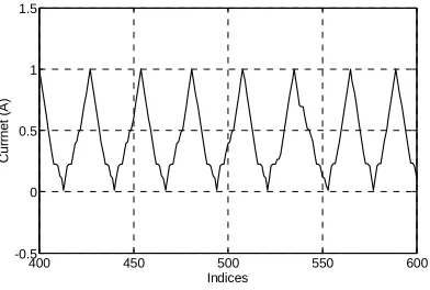
Fig.9 Output Current Waveform
Fig .9. shows the out put current wave form
inverter. The controlled by the fuzzy logic
controller.
0 1000 2000 3000 4000 5000 6000 0
0.2 0.4 0.6 0.8 1
Indices
c
o
n
tr
o
l
p
u
ls
e
Fig.10. Control Pulse
The control pulse shown in the Fig.10. this control
pulse is generated by the fuzzy logic controller.
0 2000 4000 6000 8000 10000
-20 0 20 40 60 80 100 120 140
Time(s)
P
u
ls
e
Fig. 11 Pulse For Non Linear Load
Fig. 12 Simulink For Fuzzy Controller
Fig.12. shows the fuzzy logic controller for inverter
[image:6.612.101.297.376.508.2]0.2 0.22 0.24 0.26 0.28 0.3 -400
-300 -200 -100 0 100 200 300 400
Time (s)
O
u
tp
u
t
v
o
lt
a
g
e
(
v
)
V Ref
Fig.13 Output Voltage
Fig.13 shows the output voltage waveform. It is given to single phase load.
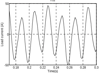
0.18 0.2 0.22 0.24 0.26 0.28 0.3 -50
0 50
Time(s)
L
o
a
d
c
u
rr
e
n
t
(A
)
V Out
Fig.14 Output Current
Fig 14. Shows the load current. The fuzzy logic controller gives the excellent performance. The DC side controller and AC side controller is controlled by the fuzzy logic. The MPPT controller is mainly controlled by the fuzzy logic and it is working good. It gives the god performance on various operating conditions.
5. CONCLUSION
A stand-alone solar-PV energy generation system with a SEPIC dc-dc converter has been designed and the performance analysis of the system has been presented under variation in solar radiations with the device currents and voltages. The harmonic distortion of the output voltage obtained under sudden load variations are also within the acceptable limit of 5% and the system is performing satisfactorily under sudden change in consumer loads and for the sudden change in solar radiations. The MPPT controller has been designed and it has performed satisfactorily for the tracking of new operating point for the solar-PV system. The
system has also been evaluated for the nonlinear loads and from the results the THD can be obtained within limits for future work.
REFERENCES:
[1] Neha Adikari, Bhim Singh, A.L. Vyas, “Performance evaluation of low power solar-PV energy system with SEPIC converter,”
IEEE PEDS 2011, Dec 2011
[2] Mummad Veerachary, “ Power tracking for nonlinear PV sources with coupled inductor SEPIC converter,” IEEE Trans, vol. 41, no.3, July 2005.
[3] Theodoros L. Kottas, Yiannis s Bourlis, Athanasios D. Karlis “ New maximum power point tracking for PV arrays using Fuzzy controller in close cooperation with Fuzzy cognitive networks,” IEEE Trans vol. 21, no. 3 Sep 2006.
[4] Mummadi veerachary, Tomonobu Senjyu, Katsumi Uezato, “ Feedforward maximum power point tracking of PV systems using fuzzy controller,” IEEE Trans vol. 38, no. 3 July 2002.
[5] Tsai-Fu Wu, Chien-Hsuan chang and Yu-kai Chen, “A fuzzy logic controlled single-stage converter for PV powered lighting system applications,” IEEE Trans vol. 47, no. 2, April 2000.
[6] F. Bouchafaa, I. Hamzaoui, A. Hadjammar, “ Fuzzy logic control for the tracking maximum power point of a PV system,’ Energy procedia, Elsvier.
[7] Trishan Esram, Patrick.I. Chapman.,
“Comparison of Photovoltaic array maximum power point tracking techniques,” IEEE Trans, vol.22, n0.2, June 2007.
[8] Mummadi veerachary, Tomonobu Senjyu, Katsumi Uezato, “ Neural network based maximum power point tracking of coupled inductor interleaved boost converter supplied PV systems using fuzzy controller,” IEEE
Trans vol. 50, no. 4 July 2003.
[image:7.612.108.276.260.384.2]