December 1, 1994
SRC
Research
Report
129
Obliq-3D
Tutorial and Reference Manual
Marc A. Najork
d i g i t a l
Systems Research Center 130 Lytton AvenueThe charter of SRC is to advance both the state of knowledge and the state of the art in computer systems. From our establishment in 1984, we have performed basic and applied research to support Digital’s business objectives. Our current work includes exploring distributed personal computing on multiple platforms, network-ing, programming technology, system modelling and management techniques, and selected applications.
Our strategy is to test the technical and practical value of our ideas by building hardware and software prototypes and using them as daily tools. Interesting systems are too complex to be evaluated solely in the abstract; extended use allows us to investigate their properties in depth. This experience is useful in the short term in refining our designs, and invaluable in the long term in advancing our knowledge. Most of the major advances in information systems have come through this strategy, including personal computing, distributed systems, and the Internet.
We also perform complementary work of a more mathematical flavor. Some of it is in established fields of theoretical computer science, such as the analysis of algorithms, computational geometry, and logics of programming. Other work explores new ground motivated by problems that arise in our systems research.
We have a strong commitment to communicating our results; exposing and testing our ideas in the research and development communities leads to improved un-derstanding. Our research report series supplements publication in professional journals and conferences. We seek users for our prototype systems among those with whom we have common interests, and we encourage collaboration with uni-versity researchers.
Obliq-3D
Tutorial and Reference Manual
Marc A. Najork
Abstract
Obliq-3D is an interpreted language that is embedded into the 3D animation system Anim3D. Anim3D is based on a few simple, yet powerful constructs that allow a programmer to describe three-dimensional scenes and animations of such scenes. Obliq-3D, by virtue of its interpretive nature, provides the programmer with a fast turnaround environment. The combination of sim-plicity and fast turnaround allows application programmers to construct non-trivial animations quickly and easily.
Contents
1 Introduction 1
1.1 Related Work
: : : : : : : : : : : : : : : : : : : : : : : : : : : : : : : : : :
12 Tutorial 4
2.1 Obliq-3D in a Nutshell
: : : : : : : : : : : : : : : : : : : : : : : : : : : : :
4 2.2 A First Example: : : : : : : : : : : : : : : : : : : : : : : : : : : : : : : :
4 2.3 Properties: : : : : : : : : : : : : : : : : : : : : : : : : : : : : : : : : : :
6 2.4 The On-Line Help Facility: : : : : : : : : : : : : : : : : : : : : : : : : : :
11 2.5 Non-Tree Scene Graphs: : : : : : : : : : : : : : : : : : : : : : : : : : : :
11 2.6 More on Property Values: : : : : : : : : : : : : : : : : : : : : : : : : : : :
13 2.7 Overloading: : : : : : : : : : : : : : : : : : : : : : : : : : : : : : : : : :
15 2.8 Behaviors: : : : : : : : : : : : : : : : : : : : : : : : : : : : : : : : : : :
16 2.9 Asynchronous Behaviors: : : : : : : : : : : : : : : : : : : : : : : : : : : :
17 2.10 Synchronous Behaviors: : : : : : : : : : : : : : : : : : : : : : : : : : : :
18 2.11 Dependent Behaviors: : : : : : : : : : : : : : : : : : : : : : : : : : : : : :
20 2.12 Locking: : : : : : : : : : : : : : : : : : : : : : : : : : : : : : : : : : : :
21 2.13 Callbacks: : : : : : : : : : : : : : : : : : : : : : : : : : : : : : : : : : : :
24 2.14 Extending Objects: : : : : : : : : : : : : : : : : : : : : : : : : : : : : : :
26 2.15 Naming Graphical Objects: : : : : : : : : : : : : : : : : : : : : : : : : : :
28 2.16 Requests: : : : : : : : : : : : : : : : : : : : : : : : : : : : : : : : : : : :
29 2.17 Depth Cueing: : : : : : : : : : : : : : : : : : : : : : : : : : : : : : : : :
32 2.18 Light Objects: : : : : : : : : : : : : : : : : : : : : : : : : : : : : : : : : :
33 2.19 Camera Objects: : : : : : : : : : : : : : : : : : : : : : : : : : : : : : : :
34 2.20 Creating Root Objects: : : : : : : : : : : : : : : : : : : : : : : : : : : : :
383 Reference Manual 41
3.13 The VectorLightGO Module
: : : : : : : : : : : : : : : : : : : : : : : : : :
58 3.14 The PointLightGO Module: : : : : : : : : : : : : : : : : : : : : : : : : : :
59 3.15 The SpotLightGO Module: : : : : : : : : : : : : : : : : : : : : : : : : : :
61 3.16 The CameraGO Module: : : : : : : : : : : : : : : : : : : : : : : : : : : :
63 3.17 The OrthoCameraGO Module: : : : : : : : : : : : : : : : : : : : : : : : :
65 3.18 The PerspCameraGO Module: : : : : : : : : : : : : : : : : : : : : : : : :
66 3.19 The LineGO Module: : : : : : : : : : : : : : : : : : : : : : : : : : : : : :
68 3.20 The MarkerGO Module: : : : : : : : : : : : : : : : : : : : : : : : : : : :
69 3.21 The SurfaceGO Module: : : : : : : : : : : : : : : : : : : : : : : : : : : :
70 3.22 The PolygonGO Module: : : : : : : : : : : : : : : : : : : : : : : : : : : :
72 3.23 The BoxGO Module: : : : : : : : : : : : : : : : : : : : : : : : : : : : : :
73 3.24 The DiskGO Module: : : : : : : : : : : : : : : : : : : : : : : : : : : : : :
74 3.25 The SphereGO Module: : : : : : : : : : : : : : : : : : : : : : : : : : : : :
75 3.26 The CylinderGO Module: : : : : : : : : : : : : : : : : : : : : : : : : : : :
76 3.27 The ConeGO Module: : : : : : : : : : : : : : : : : : : : : : : : : : : : :
77 3.28 The TorusGO Module: : : : : : : : : : : : : : : : : : : : : : : : : : : : :
78 3.29 The QuadMeshGO Module: : : : : : : : : : : : : : : : : : : : : : : : : :
79 3.30 The Prop Module: : : : : : : : : : : : : : : : : : : : : : : : : : : : : : : :
80 3.31 The BooleanProp Module: : : : : : : : : : : : : : : : : : : : : : : : : : :
82 3.32 The RealProp Module: : : : : : : : : : : : : : : : : : : : : : : : : : : : :
85 3.33 The PointProp Module: : : : : : : : : : : : : : : : : : : : : : : : : : : : :
86 3.34 The ColorProp Module: : : : : : : : : : : : : : : : : : : : : : : : : : : : :
88 3.35 The TransformProp Module: : : : : : : : : : : : : : : : : : : : : : : : : :
90 3.36 The LineTypeProp Module: : : : : : : : : : : : : : : : : : : : : : : : : : :
93 3.37 The MarkerTypeProp Module: : : : : : : : : : : : : : : : : : : : : : : : :
94 3.38 The RasterModeProp Module: : : : : : : : : : : : : : : : : : : : : : : : :
95 3.39 The ShadingProp Module: : : : : : : : : : : : : : : : : : : : : : : : : : :
96 3.40 The MouseCB Module: : : : : : : : : : : : : : : : : : : : : : : : : : : : :
97 3.41 The PositionCB Module: : : : : : : : : : : : : : : : : : : : : : : : : : : :
98 3.42 The KeyCB Module: : : : : : : : : : : : : : : : : : : : : : : : : : : : : :
99Acknowledgments 100
References 101
1
1
Introduction
Obliq [3] is a lexically-scoped, untyped, interpreted language that supports distributed object-oriented computation. The Obliq interpreter is written in Modula-3 [17], and is designed to be both easy to extend and easy to embed into other programs.
Anim3D is a Modula-3 library for building programs that use interactive, animated three-dimensional graphics. It uses the X Window System [21] as the underlying window system, and MPEX (Digital’s extension of PEX [8], the 3D extension of X) as the underlying graphics library. Support for other window systems (e.g. Trestle [14, 15]) and graphics libraries (e.g. OpenGL [18]) is under way.
Anim3D is designed to interconnect easily with an embedded language, although it does not rely on one. Possible choices for such a language are Lisp, Python, or any other interpreted language that can be easily embedded. We chose Obliq, because its linguistic features closely match those of Modula-3, and because it is particularly easy to embed an Obliq interpreter into some other Modula-3 program. The resulting embedded language is called Obliq-3D.
Obliq-3D is a superset of Obliq; it provides the same syntactic constructs, as well as all the built-in libraries described in SRC Research Report 122 [3]. In addition, it provides 42 extra modules that support the construction of 3D animations.
This report is divided into two parts. The first part gives an example-driven introduction to the basic concepts of the animation system. It assumes the reader is familiar with SRC Report 122, but does not make any further assumptions. The second part contains a reference manual for Obliq-3D. The manual contains a section for each module that is specific to Obliq-3D.
Our initial motivation for developing a fast-turnaround 3D animation system was our ex-perience in using 3D views for algorithm animation [2]. We found that building enlightening 3D animations, using a low-level graphics library such as PEXlib, was both hard and time-consuming. Since then, we have used Obliq-3D for building a variety of algorithm animations. A detailed development of one such animation (Dijkstra’s shortest-path algorithm) can be found in [16]; the accompanying videotape shows a collection of animations done with Obliq-3D.
1.1
Related Work
The last 20 years have seen a variety of device-independent 3D graphics libraries, such as Core [9], GKS-3D [11], PHIGS [1] and PHIGS+ [19]. Today’s most popular “traditional” 3D graphics libraries are PEXlib [8], IRIS GL [22], and its OpenGL variant [18].
The potential benefits of applying object-oriented methods to computer graphics have been pointed out since the inception of the oriented paradigm. Some of the earlier object-oriented libraries, such as HOOPS [27] and Dor´e [13], use an object-object-oriented design model, but provide no interface to an object-oriented language.
in C++, and provide a C++ application programmers’ interface. Inventor in particular has been quite influential. Obliq-3D adopts some of its key ideas: Scenes are modeled as directed acyclic graphs of graphical objects, and geometric primitives, cameras, and light sources are treated uniformly. But there are also some important differences. In Inventor, shapes and properties can both be added as nodes to the scene tree. This means that the order in which nodes are inserted into the tree affects the appearance of the scene: Inserting first a color node and then a sphere node will produce a different image than that obtained by adding first the sphere and then the color. Another key difference is that Inventor properties are not inherently time-variant. Animation is achieved through engines, which change the state of property nodes and shape nodes. Finally, Inventor lacks an interpreted language, a feature crucial to rapid prototyping of animations.
Paul Strauss’ “Brown Animation Generation System” [23], or BAGS for short, is one of the first 3D animation systems to provide such an embedded interpreted language (ironically, Strauss later on designed Inventor). BAGS uses an interpreted language called SCEFO to describe the structure and the animation behavior of a scene. Although quite powerful, SCEFO is an animation language, not a full-fledged programming language. It provides assignment and iteration constructs, a set of arithmetic functions, and procedural abstraction, but no conditionals. However, BAGS allows the user to write C code stubs that can be compiled into the system and can then be called from SCEFO.
BAGS was succeeded by UGA, the “Unified Graphics Architecture” [28, 10]. UGA uses an interpreted language called FLESH that is based on the prototype-and-delegation paradigm. Scenes are modeled as collections of objects. Attached to each object is a list of “change operators” or chops. Each chop defines some aspect of the appearance of an object, such as its color, transformation, and even its shape. Moreover, chops are functions of time; they are the basis for animation in UGA.
Alice [4, 5] is another rapid prototyping system for creating 3D animations. It uses Python as its embedded interpreted language. There are many commonalities between Alice and Obliq-3D. Both systems use an object-oriented interpreted language to allow for rapid prototyping. Both separate the application from the rendering. (Alice uses a process to perform the rendering; Obliq-3D uses a separate animation server thread.) Both systems allow for hierarchical geometry, that is, graphical objects that contain other graphical objects. However, the two systems differ in their basic animation model: Alice treats a scene as a hierarchy of graphical objects, each of which has a list of action routines which are called each frame of the simulation, and which are responsible for changing the internal state of the object. New animation effects are created by defining new action routines and adding them to the graphical object. Obliq-3D, on the other hand, uses properties to specify the appearance of objects; these properties are inherenty time-variant. In other words, Alice performs frame-based animation, whereas Obliq-3D has an explicit notion of time.
anima-1.1 Related Work 3
2
Tutorial
The tutorial section of this report develops the fundamental concepts of Obliq-3D, using a series of gradated examples. We start with the smallest program that actually generates a 3D image (Obliq-3D’s equivalent of “Hello World!”), and we work our way up to a level where we show how parts of the functionality of the system could be reimplemented.
The reader should be able to work his way through the tutorial within the course of a morning. All the examples are self-contained and short enough to be tried out during this reading1
.
2.1
Obliq-3D in a Nutshell
Obliq-3D (and Anim3D) is founded on three basic concepts: graphical objects for constructing scenes, time-variant properties for animating various aspects of a scene, and callbacks for providing interactive behavior.
Graphical objects subsume geometric shapes (spheres, cones, cylinders, and the like), light
sources, cameras, groups for composing complex graphical objects out of simpler ones, and
roots for displaying graphical objects on the screen.
Properties describe attributes of graphical objects, such as their color, size, location, or
orientation. A property consists of a name that determines what attribute is affected, and a
value that determines how it is affected. Property values are not simply scalar values, but rather
functions that take a time and return a scalar value. Thus, property values form the basis for animation.
Callbacks can be attached to graphical objects; they define how these objects react to events
such as key strokes or mouse position changes. Callbacks form the basis for interactive behavior.
2.2
A First Example
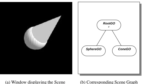
The following program is the smallest Obliq-3D program that actually creates a three-dimensional image. It opens up a graphics window on the screen, and displays a white sphere (see Figure 1a):
let r = RootGO_NewStd();
r.add(SphereGO_New([0,0,0],0.5));
(Program 1)
The first line creates a root object, which is a special kind of graphical object, and assigns it to the variabler. Associated with each root object is a window on the screen, and creating the root object creates this window and installs it on the screen.
1
2.2 A First Example 5
RootGO
r
SphereGO
[image:13.612.158.463.136.303.2](a) Window displaying the Scene (b) Corresponding Scene Graph
Figure 1: Scene and Scene Graph created by Program 1
The expressionSphereGO_New([0,0,0],0.5)creates a sphere object, which is another kind of graphical object. This particular sphere object represents a sphere whose center lies at the origin of the coordinate system, and whose radius is0
:
5units.Finally,r.add()adds the sphere object to the root object, and thereby causes it to be
displayed in the window associated with the root object. The user can manipulate the scene interactively, that is, he can move and rotate the displayed objects through mouse controls. This interactive behavior is not innate to root objects, but rather added to the root object by the functionRootGO_NewStd(). This function also creates (in addition to the root itself) a camera through which the scene is viewed, and several light sources.
Theaddmethod, which makes an object part of a larger object, is understood by all objects of typeGroupGO. In particular, it is understood by objects of typeRootGO, which is the type of root objects and a subtype ofGroupGO. This ability to group objects together into larger objects allows us to build up hierarchies of graphical objects. In general, these hierarchies must form a directed acyclic graph, called the scene graph. Figure 1b shows the scene graph corresponding to Program 1. For the sake of simplicity, the camera and the light sources that were created by the call toRootGO_NewStd()are omitted.
We can display a cone together with the sphere by adding the cone object to the root object. Here is a program that does this:
let r = RootGO_NewStd();
r.add(SphereGO_New([0,0,0],0.5)); r.add(ConeGO_New([0,0,0],[1,1,1],0.5));
RootGO
r
SphereGO ConeGO
[image:14.612.174.456.135.303.2](a) Window displaying the Scene (b) Corresponding Scene Graph
Figure 2: Scene and Scene Graph created by Program 2
The expressionConeGO_New([0,0,0],[1,1,1],0.5)creates an object that represents a cone whose base is centered at the origin and is of radius0
:
5, and whose tip lies at point(1
;
1;
1). Figure 2 shows the window associated withr, and the scene graph.All the scene graphs we have seen so far have been trees. Associated with the root of the tree was a window for viewing the scene. But it is possible to have several windows viewing the same scene. The following program creates two windows that display a scene consisting of a sphere and a cone:
let g = GroupGO_New(); RootGO_NewStd().add(g); RootGO_NewStd().add(g);
g.add(SphereGO_New([0,0,0],0.5)); g.add(ConeGO_New([0,0,0],[1,1,1],0.5));
(Program 3)
The first line creates a group object and assigns it to the variableg. The next two lines create two root objects, and addgto each. Creating the two roots also creates two windows on the screen. Finally, the last two lines create the sphere and the cone, just as in the previous example. This time, however, the sphere and the cone are not added directly to the roots, but to the group
ginstead. Figure 3 shows the two windows and the scene graph.
2.3
Properties
2.3 Properties 7
RootGO RootGO
GroupGO
g
SphereGO ConeGO
[image:15.612.154.473.137.307.2](a) The two Windows created by Program 3 (b) Corresponding Scene Graph
Figure 3: The two Windows and the Scene Graph created by Program 3
aspects of an object are described by properties.
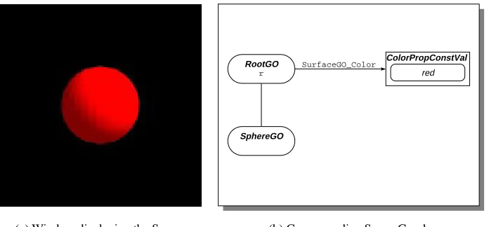
Let’s assume we want to create a scene that contains a red sphere. We can create such a scene by modifying Program 1 as follows:
let r = RootGO_NewStd();
r.add(SphereGO_New([0,0,0],0.5)); SurfaceGO_SetColor(r,"red");
(Program 4)
The first two lines create a root object which contains a sphere object. The last line “attaches” the color property “red” to the root object and all objects contained in it. Figure 4a shows the resulting scene.
TheSurfaceGOprefix indicates that the color property is associated with surfaces, that is, objects that are composed of polygons. (Sphere objects are actually approximated by polyhedra.) A property consists of two parts: a name and a value. The name describes what aspect of a graphical object is affected by the property, and the value describes what this aspect looks like. In Program 4, the name of the property isSurfaceGO_Color, and the value is the color “red”. Many properties can be attached to a graphical object. These properties form a mapping — a partial function from names to values.
In the scene graphs shown throughout this report, we represent property values through boxes. For each property that is attached to a graphical object, we draw an arrow from the oval representing the graphical object to the box representing the property value. The arrow is labeled with the property name. Figure 4b shows the scene graph created by the program above.
RootGO
r
SphereGO
ColorPropConstVal
red
SurfaceGO_Color
[image:16.612.142.490.136.298.2](a) Window displaying the Scene (b) Corresponding Scene Graph
Figure 4: Scene and Scene Graph created by Program 4
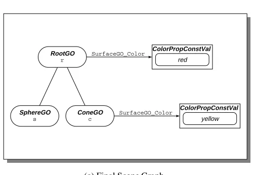
modification of Program 2:
let r = RootGO_NewStd();
let s = SphereGO_New([0,0,0],0.5); r.add(s);
let c = ConeGO_New([0,0,0],[1,1,1],0.5); r.add(c);
SurfaceGO_SetColor(r,"red");
(Program 5)
The first five lines create a root object that contains a sphere and a cone. (This time, we created names for the sphere and the cone.) The last line attaches the color property “red” to the root object. This turns the root (and with it, the sphere and the cone) red. Figure 5a shows the result. Adding the statement
SurfaceGO_SetColor(c,"yellow");
2.3 Properties 9
(a) Initial Scene (b) After setting the Color of the Cone
RootGO
r
SphereGO
s
ConeGO
c
ColorPropConstVal
red
ColorPropConstVal
yellow
SurfaceGO_Color
SurfaceGO_Color
[image:17.612.186.436.382.555.2](c) Final Scene Graph
Note that the sequence of the statements is immaterial2
(except that a variable cannot be referenced before it is declared). The following program creates exactly the same scene:
let r = RootGO_NewStd();
let s = SphereGO_New([0,0,0],0.5); let c = ConeGO_New([0,0,0],[1,1,1],0.5); SurfaceGO_SetColor(c,"yellow");
SurfaceGO_SetColor(r,"red"); r.add(c);
r.add(s);
(Program 6) Color properties are one kind of property. Other kinds include boolean properties, real properties, point properties, and so on.
Recall that properties control not only surface attributes of an object, such as its color and transparency, but also spatial attributes, such as its location and size. For example, the center of a sphere is controlled by a point property namedSphereGO_Center, and the radius is controlled by a real property namedSphereGO_Radius. The expressionSphereGO_New(c,r)creates a sphere object, and attaches a property with nameSphereGO_Centerand valuecand a property with nameSphereGO_Radiusand valuerto the new sphere object.
It is possible to detach these properties from the sphere object, using theunsetPropmethod. Consider the following program:
let r = RootGO_NewStd();
let s = SphereGO_New([0,0,0],0.5); r.add(s);
s.unsetProp(SphereGO_Center); s.unsetProp(SphereGO_Radius); SphereGO_SetCenter(r,[1,0,0]); SphereGO_SetRadius(r,0.3);
(Program 7)
The first three lines create a root objectrand a sphere objects, and addstor. The center of the sphere is at point(0
;
0;
0), and its radius is 0:
5. So far, the program is equivalent toProgram 1.
The next two lines detach the center and the radius property from the sphere object. As these properties are not defined for the root object either, the sphere is now displayed at a default location and with a default radius.
The last two lines attach a center property and a radius property to the root object. The sphere is displayed centered at point(1
;
0;
0), and with a radius of0:
3.2
2.4 The On-Line Help Facility 11
So, the center property and the color property behave exactly the same: A property attached to an object (be it a group or a sphere) affects that object and all objects contained in it, except those that have a property with the same name attached.
It should also be noted that any property can be attached to any object, but that the way an object is displayed does not necessarily depend on every property. For example, it is perfectly legal to attach aSphereGO_Centerproperty to a cone, but this will not affect the appearance of the cone.
2.4
The On-Line Help Facility
Obliq has a built-in facility that provides on-line help to the user. Typing
help;
shows a list of all preloaded libraries. You can also obtain more information on a particular library. For example, typing “help SphereGO;” reveals the types and functions exported by theSphereGOmodule:
- help SphereGO;
SphereGO_New(p: PointVal, rad: RealVal): SphereGO
SphereGO_NewWithPrec(p: PointVal, rad: RealVal, prec: Int): SphereGO SphereGO_Center: PointPropName
SphereGO_Radius: RealPropName
SphereGO_SetCenter(go: GO, center: PointVal): Ok SphereGO_SetRadius(go: GO, radius: RealVal): Ok WHERE
SphereGO <: SurfaceGO
PointVal = PointPropVal + Point3 RealVal = RealPropVal + Real + Int
The type notation follows the one described in [3]; it is reviewed at the beginning of the reference manual.
2.5
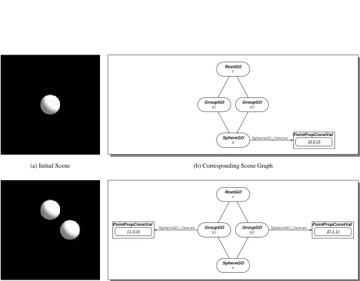
Non-Tree Scene Graphs
We mentioned before that scene graphs are directed acyclic graphs, and not simply trees. Program 3 created a scene graph with two roots (where “root” refers to a node with in-degree 0), which allowed us to view the same scene from two different vantage points.
SphereGO_Center PointPropConstVal
(0,0,0)
RootGO
r
GroupGO
g1
GroupGO
g2
SphereGO
s
(a) Initial Scene (b) Corresponding Scene Graph
SphereGO_Center
SphereGO_Center PointPropConstVal
(0,1,1)
PointPropConstVal
(1,0,0)
RootGO
r
GroupGO
g1
GroupGO
g2
SphereGO
s
[image:20.612.46.568.134.541.2](c) Final Scene (d) Corresponding Scene Graph
2.6 More on Property Values 13
let r = RootGO_NewStd(); let g1 = GroupGO_New(); r.add(g1);
let g2 = GroupGO_New(); r.add(g2);
let s = SphereGO_New([0,0,0],0.5); g1.add(s);
g2.add(s);
(Program 8) This program creates a root object that contains two group objects that in turn both contain the same sphere object. The program so far displays a scene that apparently contains a single sphere (see Figure 6a). However, adding the following three lines reveals that there are really two spheres in the scene, which just happen to be superimposed:
s.unsetProp(SphereGO_Center); SphereGO_SetCenter(g1,[1,0,0]); SphereGO_SetCenter(g2,[0,1,1]);
(Program 8— continued)
These statements detach the center property from the sphere object, and attach two differing center properties to the groupsg1andg2. This causes the sphere to be shown at the location described by the center property attached tog1, and also at the location described by the center property attached tog2(see Figure 6c).
We can describe the semantics of scene graphs with multiple paths between any pair of nodes in a procedural fashion: For each path between a root node
r
and a leaf nodel
,l
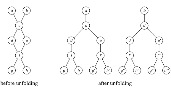
is rendered once, using the current value of the properties attached to the nodes along this path.We can also describe it in a more declarative way: Every scene graph can be “unfolded” into a forest of scene trees. Table 1 gives an algorithm for performing the unfolding, and Figure 7 shows an example of an unfolding.
2.6
More on Property Values
Let’s take a closer look at property values. A property value represents a time-variant value. It is implemented as an Obliq object that has a methodvaluewhich takes a time and returns the value at that time.
So far, we have seen only constant property values, that is, property values that do not change over time. The expressionRealProp_NewConst(0.5)creates a new real property value, whose value is0
:
5regardless of the current time.INPUT: Scene graph
G
.G
is a directed acyclic graph. OUTPUT: Unfolded scene graphG
0.
G
0is a forest of trees.
1. Let
G
0be the empty graph.
2. Add an artificial source vertex
s
toG
. Add artificial arcs froms
to every vertex inG
with in-degree 0.3. For every vertex
u
inG
and each pathp
froms
tou
, add a vertexu
p
toG
0. We say that
u
p
corresponds tou
.4. For each arc(
u;v
)inG
, and for all verticesu
p
,v
p
0inG
0such that
u
p
corresponds tou
,v
p
0 corresponds tov
, andp
0
=
pv
, add an arc (u
p
;v
p
0)to
G
0
. We say that
(
u
p
;v
p
0)corresponds to (
u;v
).5. Remove the artificial source vertex and arcs from
G
, and the corresponding vertex and arcs fromG
0 [image:22.612.107.515.90.619.2].
Table 1: Unfolding of Scene Graphs
a b
c
d e
f
g h
a b
c c’
d e d’ e’
f f’ f’’ f’’’
g h g’ h’ g’’ h’’ g’’’ h’’’
before unfolding after unfolding
[image:22.612.163.452.461.610.2]2.7 Overloading 15
RealPropConstVal
0.5
RootGO
r
SphereGO SphereGO_Radius SphereGO_Radius SphereGO
[image:23.612.79.532.120.293.2](a) Window displaying the scene (b) Corresponding Scene Graph
Figure 8: Scene and Scene Graph created by Program 9
let r = RootGO_NewStd();
let rad = RealProp_NewConst(0.5); r.add(SphereGO_New([-1,0,0],rad)); r.add(SphereGO_New([1,0,0],rad));
(Program 9) Figure 8 shows the scene displayed by the program, together with the corresponding scene graph. The scene contains two spheres; the radius of each sphere is controlled by the real property valuerad. Changingradaffects both spheres.
The ability to attach the same property value to several graphical objects provides us with an alternative to “property inheritance”. In the example above, instead of attachingradto each sphere, we could have attached it to their common ancestorrinstead. If no other radius property were attached to either sphere, then the radius of both spheres would have been “inherited” from
r. However, there are many cases in which the “natural” structure of the scene graph prevents us from using property inheritance. For example, in a scene describing a car, we might want to put two tires and an axle into the same group, but we also want the four tires to have the same color, and the two axles to have a different color. Having the tires and the axle in the same group prevents us from using property inheritance to describe their color; in such a case, shared property values are the best solution.
2.7
Overloading
a property value (e.g. a RealPropVal)
raw extend getBeh setBeh value get
a behavior (e.g. a RealPropConstBeh)
[image:24.612.208.416.146.255.2]raw extend set
Figure 9: Properties and Behaviors
accepts arguments of different types. SphereGO_Newaccepts either points or point property values as the first argument, and either integers, reals, or real property values as the second argument. A point, in turn, is an array of three elements, which can be either integers or reals.
It is important to remember that only the 3D functions of Obliq-3D are overloaded. The rest of Obliq distinguishes between, say, integers and reals, and these types cannot be freely interchanged. For example, the expression1 + 0.1will cause a run-time error.
2.8
Behaviors
There are many different ways in which a property value might change over time. It might remain constant, it might change perpetually, it might start to change from one value to another when signaled, and so on.
When a property value is attached to a single graphical object, we can change the way this property value changes over time simply by replacing it with another one. But this approach is impractical when the property value is attached to many graphical objects. So, instead of replacing the entire property value by a new one (and having to update every graphical object that uses this property value), we simply change the behavior of the property value.
Behaviors, just like property values, are represented by Obliq objects. In a sense, property values serve merely as “clerks” for behaviors: they forward value-inquiring messages from the client program or the animation server to the behavior. Replacing one behavior with another one is transparent to the client program and the animation server because the property value acts as an intermediary. Figure 9 illustrates this encapsulation.
Constant property values are really property values that contain constant behaviors. A property value might change from being constant to being time-variant during its lifetime, while a constant behavior will remain constant for its entire existence.
2.9 Asynchronous Behaviors 17
Figure 10: Snapshots of the animation created by Program 10
The callb.set(0.7)will changeb’s value from0
:
5to0:
7.We can access the behavior of a property value by sending the message getBeh()to the property value. Recall Program 9, which displays two spheres whose radius is controlled by the constant property valuerad. The following statement changes the radius of the two spheres to
0
:
3:rad.getBeh().set(0.3);
We can replace the behavior of a property value by sending it thesetBeh message. For example, rad.setBeh(RealProp_NewConstBeh(0.7));
will replace the existing behavior ofradwith a new behavior that always evaluates to0
:
7.2.9
Asynchronous Behaviors
As we said before, both property values and behaviors represent time-variant values. A behavior implements a function from a moment in time to the actual value at that time3
; the property value serves as an intermediary between graphical objects and behaviors, allowing us to exchange behaviors without having to update graphical objects.
In the previous section, we encountered the most primitive form of behaviors, namely constant behaviors, that is, behaviors whose value does not change (unless explicitly changed through asetmessage).
Asynchronous behaviors are the second class of behaviors in our system. Asynchronous
behaviors change over time; and they change throughout their entire lifetime. They do not depend on other property values, and they do not synchronize their changes with them.
The following program displays a sphere, whose radius oscillates between0
:
3and0:
7:let root = RootGO_NewStd();
let rad = RealProp_NewAsync(meth(self,time) 0.5 + math_sin(time) * 0.2 end); root.add(SphereGO_New([0,0,0],rad));
(Program 10)
3
The second line creates a new real property valueradwith an asynchronous behavior. This behavior is defined by a method that takes two arguments, the behavior itself and the current time, and returns a real. In this case, the value ofradat time
t
is defined to be0:
2sin (t
)+0:
5.4
radis attached as the radius property to a sphere object, which causes the sphere to pulse. Figure 10 shows a “film-strip” of successive snapshots of the scene generated by this program.
2.10
Synchronous Behaviors
A synchronous behavior represents a value that does not change continuously, but rather upon being signaled. Each synchronous behavior is connected to a synchronization object, called an
animation handle. We say that the animation handle controls the behavior. Many synchronous
behaviors can be controlled by the same handle.
Conceptually, a synchronous behavior consists of a current value and a request queue. Requests are objects that change the current value of the behavior. For each type of behavior, there is a set of predefined requests that perform linear interpolations between the current value of the behavior and a new one; in addition, the client program can define arbitrary new requests. Each synchronous behavior has methods for adding predefined and user-defined requests to its request queue; these requests will be processed once the animation handle controlling the behavior is signaled.
Associated with each request is a start time and a duration. A request with start time
s
and durationd
starts to affect the value of the behaviors
seconds after the controlling animation handle is signaled, and ceases to do sod
seconds later.The following program demonstrates the use of synchronous behaviors:
let ah = AnimHandle_New();
let p = PointProp_NewSync(ah,[0,0,0]); let c = ColorProp_NewSync(ah,"red"); let r = RootGO_NewStd();
let s = SphereGO_New(p,0.5); r.add(s);
SurfaceGO_SetColor(s,c);
p.getBeh().linMoveTo([0,1,0],1,3); c.getBeh().rgbLinChangeTo("green",0,4); ah.animate();
(Program 11)
The first line creates a new animation handleah. The next two lines create a point property valuepwhose initial value is(0
;
0;
0), and a color property valuecwhose initial value is “red”.Bothpandcare synchronous property values (that is, property values containing a synchronous behavior), and both are controlled by the animation handleah.
4
2.10 Synchronous Behaviors 19
SurfaceGO_Color
SphereGO_Center
RootGO
r
SphereGO
s
ColorPropVal c
a ColorPropSyncBeh
current value: red request queue:
PointPropVal p
a PointPropSyncBeh
current value: (0,0,0) request queue:
AnimHandle ah
rgbLinChangeTo request
target value: green start time: 0 duration: 4
linMoveTo request
[image:27.612.102.521.124.360.2]target value: (0,1,0) start time: 1 duration: 3
Figure 11: Scene Graph created by Program 11
The next three lines create a root object, which contains a sphere object. The center of the sphere depends on the current value ofp, and its color depends on the current value ofc. So, initially the sphere is red, and centered at the origin.
In the next line, we send the messagelinMoveToto the behavior ofp, asking it to change from its present value to(0
;
1;
0). This change will start 1 second after the animation handle issignaled, and will take 3 seconds to complete. Similarly, we send a messagergbLinChangeTo
to the behavior ofc, asking it to change from its present value (that is, red) to green. The change will start right when the animation handle is signaled, and will take 4 seconds to complete. Figure 11 shows the state of the scene graph after this message.
Up to this point, no changes have actually taken place. Sending the message animateto the animation handleahcauses the requests to be processed. Theah.animate()call returns only after all requests have been processed, that is, it will run for 4 seconds.
Many requests can be added to the request queue of a synchronous behavior. However, the time intervals of these requests must not overlap. So,
let c = ColorProp_NewSync(ah, "red"); c.getBeh().rgbLinChangeTo("green",0,2); c.getBeh().rgbLinChangeTo("blue",2,2);
let c = ColorProp_NewSync(ah, "red"); c.getBeh().rgbLinChangeTo("green",0,2); c.getBeh().rgbLinChangeTo("blue",1,2);
is illegal, and will cause an Obliq exception to be raised. It should also be noted that zero-duration intervals are closed, whereas others are open. So
let c = ColorProp_NewSync(ah, "red"); c.getBeh().rgbLinChangeTo("green",0,0); c.getBeh().rgbLinChangeTo("blue",0,2);
is legal, as the intervals[0
;
0]and(0;
2)do not overlap, whereaslet c = ColorProp_NewSync(ah, "red"); c.getBeh().rgbLinChangeTo("green",0,0); c.getBeh().rgbLinChangeTo("blue",0,0);
is illegal, because[0
;
0]and[0;
0]overlap.2.11
Dependent Behaviors
A dependent behavior is a behavior whose value depends on other property values. Dependent behaviors allow us to specify functional dependencies between property values. Such depen-dencies are often called one-way constraints. It is a checked run-time error if the dependency graph induced by the dependent behaviors includes any cycles.
A dependent behavior is defined just like an asynchronous behavior, through a method that is passed to its creation function. This method takes the behavior itself and the current time as arguments, and returns the value for the behavior at that time.
The following program creates a sphere and a torus. The radius of the sphere is defined by an asynchronous property value, which causes the sphere to pulsate. The radius of the torus is dependent on the radius of the sphere; it will always be 1.5 times as large.
let root = RootGO_NewStd();
let rad1 = RealProp_NewAsync(meth(self,time) 0.5 + math_sin(time) * 0.2 end); root.add (SphereGO_New ([0,0,0],rad1));
let rad2 = RealProp_NewDep (meth(self,time) rad1.value(time) * 1.5 end); root.add (TorusGO_New([0,0,0], [0,1,0], rad2, 0.1));
(Program 12)
The first three lines of this program are identical to Program 10. The fourth line defines a new dependent property valuerad2, whose value at a given time is 1.5 times the value ofrad1
at that time. The last line creates a torus, whose center is(0
;
0;
0)and whose normal vector is(0
;
1;
0). The major radius of the torus is defined to berad1, and the minor radius has a constantvalue of0
:
1.2.12 Locking 21
Figure 12: Snapshots of the animation created by Program 12
2.12
Locking
You may have noticed that none of the programs we have shown contained an explicit statement to draw the scene. Obliq-3D is based on a damage-repair model: modifying the scene graph damages the scene, that is, the scene shown on the screen is no longer consistent with the scene graph. An animation server thread detects any damage, and repairs it by redrawing the scene.
This model is intriguing because of its simplicity, and because it minimizes the amount of Obliq-3D code a user has to write. However, there are cases where we would like a set of changes to the scene graph to be atomic; that is, we do not want the animation server to redraw the scene before we have performed all the changes.
We can declare a set of operations to be atomic by surrounding them with a locking construct. There is a global lockAnim3D_lock, which the animation server must hold in order to perform any redrawing. So, acquiring this lock prevents the animation server from redrawing the scene. The following program demonstrates the use of this locking facility. The aim of this program is to visualize a simple data structure, namely a binary search tree. We want to show each key as a color-coded sphere, where colors range from yellow over green, cyan, blue, and magenta to red. Yellow corresponds to a small key, whereas red corresponds to a large key.
let rec Insert = proc (tr, el)
if tr is ok then
{key => el, left => ok, right => ok} elsif tr.key > el then
{key => tr.key, left => Insert (tr.left, el), right => tr.right} else
{key => tr.key, left => tr.left, right => Insert (tr.right, el)} end
end;
let maxkey = 10;
let KeyColor =
proc (key) color_hsv(real_float(key)/real_float(maxkey), 1.0, 1.0) end;
let leftXf = Matrix4_Translate(Matrix4_Scale(Matrix4_Id,0.5,0.5,0.5),-1,-2,0); let rightXf = Matrix4_Translate(Matrix4_Scale(Matrix4_Id,0.5,0.5,0.5), 1,-2,0);
let rec VisTree = proc (tr)
let g = GroupGO_New(); if tr isnot ok then
let node = SphereGO_New ([0,0,0],0.4); SurfaceGO_SetColor(node, KeyColor (tr.key)); g.add(node);
if tr.left isnot ok then
g.add(LineGO_New([0,0,0],[-1,-2,0])); let left = VisTree(tr.left);
GO_SetTransform(left,leftXf); g.add(left);
end;
if tr.right isnot ok then
g.add(LineGO_New([0,0,0],[1,-2,0])); let right = VisTree(tr.right); GO_SetTransform(right,rightXf); g.add(right);
end; end; g; end;
2.12 Locking 23
let Run =
proc (keylist) var tree = ok;
let root = RootGO_NewStd(); let treeRoot = GroupGO_New(); root.add (treeRoot);
foreach key in keylist do tree := Insert (tree, key); lock Anim3D_lock do
treeRoot.flush();
treeRoot.add(VisTree(tree)); end;
thread_pause(2.0); end;
end;
Run ([5,3,7,2,10,8,4,6,1,9]);
(Program 13— continued)
Trees are represented as objects with three fields: keyfor the key,leftfor the left subtree, andrightfor the right subtree. The empty tree is represented by the valueok(Obliq’s equivalent ofNIL).
Insertis a function that takes a binary search treetrand an elementelto be inserted, and returns the tree that results from insertingelintotras a leaf node.Inserthas no side effects.
Keycoloris a function that takes a key (i.e. a number) and returns a color corresponding to this number. KeyColorrelies on the constantmaxkey, which indicates the largest key that should be expected.
VisTreeis a function that takes a tree and returns a graphical object representing the tree.
VisTreeworks as follows: First, it creates a new group objectg. If the tree is empty, it simply returns the empty group, otherwise, it creates a sphere centered at the origin, attaches a color corresponding to the key of the root to the sphere, and adds the sphere tog. If the left subtree is not empty, it also adds a line from the sphere to the position where the root of the left subtree is. It then calls itself recursively, obtaining a graphical objectleftcontaining the left subtree. The sphere representing the root of this left subtree again lies at the origin. VisTreeattaches a transformation matrixleftXftoleft, which shifts the entire subtree down and to the left, and also scales it down to half its size. Then,VisTreeaddslefttog. The right subtree is visualized analogously. Finally,VisTreereturns the group g, which now contains graphical objects visualizing the entire tree. It should be noted thatVisTreeis entirely functional; it has no side-effects whatsoever.
Run is the main procedure of the program. It takes an array of keys as an argument. It starts out by creating an empty treetree, a root objectroot, and a group objecttreeRootto contain the visualization oftree. treeRootis added as a child toroot. The main loop of
Figure 13: Final state of the animation created by Program 13
is updated. The update consists of two steps: first, we flushtreeRoot, discarding the previous visualization of the tree. Second, we call VisTreeto obtain a graphical object showing the new tree, and add this object totreeRoot. To prevent flicker, these two steps must be atomic, so they are protected by a locking construct that acquiresAnim3D_lock. The main loop ends with a call tothread_pause, which causes the program to pause for two seconds during each iteration, making the visualization easier to follow.
The last line invokes our program on a small test case. Figure 13 shows the scene visualizing the final state of the tree.
2.13
Callbacks
So far, we have encountered two major concepts: graphical objects, which provide various geometric primitives and which allow us to arrange the primitives into hierarchies; and properties, which determine the appearance of graphical objects (apart from their intrinsic shape), and which are the basic vehicle for animation. The third major concept in Obliq-3D are callbacks: objects which are used to specify the way a graphical object reacts to input events.
We distinguish between three different kinds of events: mouse events, which are triggered by mouse button transitions; position events, which are triggered by changes in the mouse position; and key events, which are triggered by keyboard key transitions. For each kind of event, there is a corresponding type of callback object.
2.13 Callbacks 25
press or a release, what the position of the mouse was, and what other buttons or option keys were pressed at this time).
Associated with every graphical object is a mouse callback stack, that is, a stack for mouse callback objects. When a graphical object receives aninvokeMouseCB(mr)message, it checks if there are any callback objects on its mouse callback stack. If there is one, it sends the message
invoke(mr)to the topmost callback object; if not, the mouse event is ignored.
Each mouse callback object has a correspondinginvokemethod that takes two arguments: the callback object itself and a mouse event record. The invoke method is responsible for deciding what action should be taken in order to respond to the callback. Possibilities are to simply ignore it, to forward it to other graphical objects (this makes sense particularly for group objects), or to change some property values (for instance transformation properties, to rotate the scene).
Mouse callback objects are created through the MouseCB_New function, which takes a method as its argument and assigns it to theinvokefield of the new mouse callback object.
The client program can push new mouse callback objects onto the mouse callback stack of a graphical object by sending thepushMouseCBmethod to that object, and it can remove the top or an arbitrary callback object from the stack by sending the messagespopMouseCBor
removeMouseCBto the graphical object. Pushing a callback object means establishing a new reactive behavior, and popping the stack means reverting back to a previous behavior.
The following example demonstrates the use of a mouse callback. The program initially shows a sphere. Whenever the user presses the left mouse button, the sphere is replaced by a box, and when he releases the button, the sphere reappears.
let root = RootGO_NewStd();
let ball = SphereGO_New ([0,0,0], 1); let box = BoxGO_New ([-1,-1,-1],[1,1,1]); root.add(ball);
let M = meth(self,mr)
if (mr.change is "Left") then
if (mr.clickType is "FirstDown") or (mr.clickType is "OtherDown") then root.remove(ball);
root.add(box); else
root.remove(box); root.add(ball); end;
end; end;
root.pushMouseCB(MouseCB_New(M));
Obliq ProxiedObj
opaque Obliq value
Modula-3 ProxiedObj.T
[image:34.612.250.372.144.267.2]Modula-3 forwarder object
Figure 14: Obliq and Modula-3 counterparts of a Proxied Object
2.14
Extending Objects
Obliq has acloneconstruct, which takes an arbitrary number of objects and returns a new object which is the “concatenation” of the arguments. More precisely,clonerequires the sets of field names of the argument objects to be pairwise disjoint, and it returns a new object whose set of field names is the union of the sets of field names of the arguments, and whose field contents are identical to the contents of the corresponding fields of the argument objects.
The clone construct fulfills several purposes: it provides a mechanism for performing a shallow copy of an object, and it allows us to extend objects (that is, add additional fields).
There is a restriction in Obliq-3D that certain objects must not be cloned. To understand the reason for this, we have to understand the connection between Obliq-3D and the underlying Modula-3 animation library Anim3D.
Obliq-3D provides a variety of different object types: graphical objects (objects of type
GO), property names (PropName), property values (PropVal), property behaviors (PropBeh), and so on. All of these are subtypes of ProxiedObj, the type of proxied objects. In our terminology, a proxied object is an Obliq object with a Modula-3 counterpart. Conversely, on the Anim3D side, there is a typeProxiedObj.Twith subtypesGO.T,Prop.Name,Prop.Val,
Prop.Beh, and so on. The two objects are connected to each other: the ObliqProxiedObj
will forward certain messages to the Modula-3ProxiedObj.T, and the Modula-3 object can in turn invoke methods of the Obliq object. Figure 14 illustrates the relationship.
Each ProxiedObj has (at least) two fields: raw and extend. The raw field contains an opaque Obliq value, which in turn contains a reference to the corresponding Modula-3 ProxiedObj.T. The Modula-3 object could in turn contain a pointer back to the Obliq
2.14 Extending Objects 27
opaque Obliq value
Modula-3 ProxiedObj.T
Modula-3 forwarder object original
Obliq ProxiedObj
opaque Obliq value
Modula-3 ProxiedObj.T
Modula-3 forwarder object original
Obliq ProxiedObj cloned
Obliq ProxiedObj
[image:35.612.147.472.141.298.2](a)Before callingclone (b)After callingclone
Figure 15: The effect ofcloneon Proxied Objects
object, whose signature is not Obliq-specific, between the Modula-3ProxiedObj.Tand the ObliqProxiedObj.
The important point to remember is that an ObliqProxiedObjand a Modula-3ProxiedObj.T
refer to each other, and that there is a one-to-one relationship between them. So what would happen if we clone an Obliq object? Assume we have a behavior objectbehwith a Modula-3 counterpartx. The relationship between the two objects is shown in Figure 15a. Executing the statement
let beh2 = clone (beh, {newField => ...});
will create a new behaviorbeh2, which has an extra fieldnewField. But therawfield ofbeh2
still refers to the same opaque value and therefore to the same Modula-3 objectx. xin turn still refers tobeh, not tobeh2(see Figure 15b). This might have fatal consequences. For instance, we would expect that
pv.setBeh(beh2);
should makebeh2the behavior of the property valuepv. However,pv.getBeh()will return
behinstead ofbeh2, as the Modula-3 counterpart ofbeh2still points back tobeh.
To overcome this problem, Obliq-3D offers an alternative way to extend ProxiedObj
objects. Each ProxiedObj p has a method extend, which takes a second Obliq object o
original Obliq ProxiedObj
opaque Obliq value
Modula-3 ProxiedObj.T
Modula-3 forwarder object
original Obliq ProxiedObj
opaque Obliq value
Modula-3 ProxiedObj.T
Modula-3 forwarder object extended
Obliq ProxiedObj
[image:36.612.149.476.138.296.2](a)Before callingextend (b)After callingextend
Figure 16: The effect ofextendon Proxied Objects
effect ofextend.
2.15
Naming Graphical Objects
There are cases where it would be convenient to find a particular graphical object within a scene graph, without having to traverse the graph.
In order to build such a facility for finding objects in a scene graph, we have to decide on how to identify the object we are searching for. We could use the object itself as a search key, but that would be somewhat useless: if we already have the object, why search for it?
An alternative is to attach a symbolic label, a name, to graphical objects, and then search for them by name. In Obliq-3D, a namen is simply a value of typeText. We can attachn
to a graphical objectg by callingg.setName(n). We can also inquire the name of a given graphical object:g.getName()returns the name ofgif it is defined, andokotherwise. Finally,
g.findName(n)traverses the scene graph to see if gor any of its descendants are namedn; if so, it returns the object namedn, otherwise, it returnsok. If there are several nodes with the same name in the scene graph,findNamewill return the one it finds first.
We have indicated before (see page 5) that the expression RootGO_NewStd(), which creates a new root object and returns it, also attaches a camera and several light sources to it. The naming facility give us the ability to access these objects. The name of the camera that comes with the standard root object isdefault-camera, the name of the first light source is
2.16 Requests 29
2.16
Requests
Section 2.10 explained how synchronous behaviors can be used to change a property value from its current value to a new one. At least for continuous property values (e.g. reals, points, colors, and transformations), this implies that some interpolation between the initial value and the new one must be performed, in order to make the transition appear smooth. Each synchronous behavior provides one or more default interpolation methods. These methods create a request object for performing the interpolation, and they add the request to the behavior’s request queue. Synchronous real behaviors have a method linChangeTo, which performs a linear, i.e. constant-speed, interpolation between the two values. Synchronous point behaviors have meth-ods linMoveTo and linMoveBy which move at a constant speed and over a straight path through 3-space, either to a specified point, or by a specified amount. Synchronous color behav-iors provide a methodrgbLinChangeTowhich interpolates between the two colors such that the intermediate values move at a constant speed over a straight path through RGB space5
. Syn-chronous transformations provide a methodchangeTothat interpolates between two (slightly restricted) transformation matrices by using a rather complicated technique.
But what if you want to use a different interpolation method? For instance, you might want to change a color property value from its current value to a new one, but move on a straight path through HSV-space6
instead of RGB-space. Obliq-3D enables you to do just that by allowing you to create arbitrary request objects, which encapsulate an interpolation method. All the interpolation methods that are provided by default are implemented in terms of request objects. A color request object is created by calling the functionColorProp_NewRequest. This function takes the desired start time of the interpolation (relative to the time at which the controlling animation handle is signaled), its desired duration, and a method m, which will be used to interpolate between the initial color value and the desired new one. mtakes three arguments: the request itself, a color that shall be the value to start interpolating from, and the time that has elapsed since the controlling animation handle was signaled. It returns the value the color shall have at this time.
Color request objects have three methods in addition to the normalrawandextendfields, which contain the values passed toColorProp_NewRequest. The methodstartreturns the time at which the interpolation shall start, the methoddurreturns its desired duration, and the methodvalueperforms the actual interpolation. Virtually every request object will be extended to contain some additional fields, such as the target value of the interpolation.
A request objectrcan be added to the request queue of a synchronous behaviorbby calling
5
RGB stands for “Red-Green-Blue”. An RGB value consists of a red, a green, and a blue component, indicating the intensity of these primary colors.
6
b.addRequest(r). The time intervals of requests in the request queue must not overlap. Let us extend the type of synchronous color behaviors by adding a new method
hsvLinChangeTo to it. This method shall have the same signature as rgbLinChangeTo, but shall interpolate on a straight line through HSV space instead of RGB space.
In order to do this, we have to replace the functions ColorProp_NewSync and
ColorProp_NewSyncBehby new versions, which create the extended version of the color behavior. So, we have to “re-open” theColorPropmodule and add to it:
module MyColorProp for ColorProp;
let valueMeth =
meth (self, startcol, reltime)
let frac = (if (self.dur() isnot 0.0) then
(reltime - self.start()) / self.dur(); else
1.0; end);
let h = color_h(startcol), s = color_s(startcol), v = color_v(startcol); color_hsv (h + ((self.h - h) * frac),
s + ((self.s - s) * frac), v + ((self.v - v) * frac)); end;
let hsvLinChangeTo =
meth (self, col, start, dur)
let c = ColorProp_NewConst (col).get(); (* make the 1st arg overloaded *) self.addRequest (ColorProp_NewRequest(start, dur, valueMeth).extend(
{h => color_h(c), s => color_s(c), v => color_v(c)})); end;
let NewSync = proc (ah, col)
let pv = ColorProp_NewSync(ah, col);
pv.setBeh(pv.getBeh().extend ({hsvLinChangeTo => hsvLinChangeTo})); pv;
end;
let NewSyncBeh = proc (ah, col)
ColorProp_NewSyncBeh(ah, col).extend({hsvLinChangeTo => hsvLinChangeTo}); end;
end module;
2.16 Requests 31
valueMethis the interpolation method. It takes three arguments: self, startcol, the initial value of the color, andreltime, the time that has elapsed since the animation handle was signaled. The request objectselfcontains the usual methodsstart, dur, andvalue; it also contains three extra fieldsh,s, andv, which hold the hue, saturation, and value of the target color of the interpolation. valueMethfirst computes what fraction of the interpolation has already elapsed. If the interpolation has a zero duration, then this fraction is assumed to be 1. Next,valueMethextracts theh,s, andvcomponents of the initial color. Finally, it interpolates between theh,s, andvcomponents of the initial and the final color, and returns the resulting intermediate color.
The method hsvLinChangeTo takes a behavior self, a target color col, a start time
start, and a durationdur. We would like to allowcolto be overloaded, that is, to be either aColoror aTextdenoting a color. But as the operations in thecolormodule cannot deal with such overloading, we have first to convert col into a value that is guaranteed to be a color. We do so by using the overloaded functionColorProp_NewConstto create a constant
ColorPropVal, and then extract its current value. Then, we callColorProp_NewRequest
to create a new request object with start timestart, durationdur, and interpolation method
valueMeth. We extend this object by three fieldsh,s, andv, which contain the hue, saturation, and value components ofcol, and finally we return the extended object.
The last two procedures NewSync and NewSyncBeh replace the default procedures for creating synchronous color property values and behaviors. NewSyncfirst invokes the original version of NewSync to create a new property valuepv. It then extracts the behavior of pv, extends this behavior by a new methodhsvLinChangeTo, and replaces the original behavior with the extended one. Finally, it returnspv.
NewSyncBeh simply invokes the original version of NewSyncBeh to create a new syn-chronous behavior, extends this behavior by a new methodhsvLinChangeTo, and returns the extended behavior.
Ending the module causes NewSync and NewSyncBeh to be accessible as
ColorProp_NewSync andColorProp_NewSyncBeh, thereby truly hiding the default pro-cedures.
We can test the extended version of color property values with the following program:
let root = RootGO_NewStd();
let ball = SphereGO_New ([0,0,0], 0.5); root.add (ball);
let ah = AnimHandle_New();
let col = ColorProp_NewSync (ah, "yellow"); SurfaceGO_SetColor (ball, col);
col.getBeh().hsvLinChangeTo ("blue", 0, 2); ah.animate ();
This program creates a root object, which contains a sphere. Attached to the sphere is a synchronous color property value, which is initially yellow. This color property value differs from the normal ones in that its behavior understands one extra method, namelyhsvLinChangeTo. We send such a message to the behavior, asking it to turn blue, over the course of two seconds. If we had used thergbLinChangeTorequest, the color would have changed from yellow over grey to blue. ThehsvLinChangeTomessage, however, causes it to move “through the rainbow”, that is, from yellow over green to blue.
2.17
Depth Cueing
Depth cueing (also known as “fog”) simulates the effects of atmosphere and the dimming of objects as they become more distant. Objects “fade” towards a color, called the depth cue color, the further they are away from the viewer.
Depth cueing can be switched on or off. If it is on, its effect is determined by five parameters: a front plane
P
f
, a back planeP
b
, a front scale factorS
f
, a back scale factorS
b
, and a depth cuecolor
C
d
.The part of the scene that is displayed by a given root object is surrounded by a “bounding box”7
. The front face of the bounding box is orthogonal to the viewing direction of the camera. The box is treated as a unit cube; the z-coordinate of its front face is 1, and the z-coordinate of its back face is 0.
P
f
andP
b
are two real numbers that describe the z-coordinates of two planes within this unit cube, so they can range between 0 and 1.Given an object (or a part of an object) whose z-coordinate (normalized to the bounding box) is
z
and whose reflected color (i.e. the color determined by lighting and shading computations) isC
r
, the color after depth cueing of this object isC
r
+(1 )C
d
, where: =8
> <
> :
S
b
ifz
P
b
(i.e. the part is behind the back plane)S
b
+(S
f
S
b
)z P
b
P
fP
bif
P
b
< z < P
f
S
f
ifP
f
z
Figure 17 plots the value of
as a function ofz
.Depth cueing is associated with a root object. It affects all the objects shown in the window that corresponds to this root.
C
d
is controlled by the color property named RootGO_Depthcue-Color;P
f
andP
b
are controlled by the real properties RootGO_DepthcueFrontPlaneand RootGO_DepthcueBackPlane;
S
f
andS
b
are controlled by the real propertiesRootGO_DepthcueFrontScale and RootGO_DepthcueBackScale; and whether depth cueing is in effect or not is controlled by the boolean property namedRootGO_DepthcueSwitch.
The following program shows how depth cueing can be used. It also makes clear that, because depth cueing is controlled by properties, all the standard mechanisms for animation
7
2.18 Light Objects 33
0 1
0 1
Pb Pf
b
S
f
S
z
α
[image:41.612.201.414.140.279.2]Back Front
Figure 17: Relationship between fading factorand depthzin depth cueing
are available to control it. The program constructs a scene that shows a cone. Depth cueing is switched on, and the back scaling factor is made to oscillate between 0 (far objects fade almost fully into black) and 1 (objects do not fade away).
let root = RootGO_NewStd();
root.add (ConeGO_New([0,0,0],[0,0,50],1));
let bs = RealProp_NewAsync(meth(self,time) 0.5 + math_sin(time) * 0.5 end); RootGO_SetDepthcueBackScale(root, bs);
RootGO_SetDepthcueSwitch(root, true);
(Program 16)
2.18
Light Objects
In Section 2.2 and again in Section 2.15, we mentioned that the functionRootGO_NewStd()
creates two light sources along with a root object, and adds these light sources to the new root. Light sources are treated as ordinary graphical objects: they can be added to groups, prop-erties can be attached to them, and their effect is controlled by propprop-erties.
Figure 18: Snapshots of the animation created by Program 17
let root = RootGO_NewStd();
root.remove(root.findName("default-vector-light")); root.add(CylinderGO_New([0,0,-0.5],[0,0,0.5],1)); let g = GroupGO_New();
root.add(g);
g.add(ConeGO_New([0.5,0,0],[0,0,0],0.2));
g.add(SpotLightGO_New("white",[0,0,0],[0.5,0,0],1,1,0.5,0.5)); let rot = TransformProp_NewAsync (meth(self, time)
Matrix4_RotateZ(Matrix4_Id, time) end);
GO_SetTransform(g, rot);
(Program 17) First, we call RootGO_NewStd() to create a root object root. This call also creates an ambient and a vector light source. We remove the vector light source (which is named
"default-vector-light") fromroot, and add a cylinder toroot.
Next, we create a group objectg, addgtoroot, and add a cone and a spot light source to
g. The tip and the central axis of the cone object and the light cone emitted by the spot light coincide.
Finally, we create an asynchronous transformation property value, which continuously rotates around the
z
axis, and attach it tog. This causesgand all objects contained in it (i.e. the cone and the spot light) to rotate around thez
axis.The animation created by this program shows that the cone of light emitted by the spot light sweeps across the walls of the cylinder. Figure 18 shows a series of snapshots of the animation in progress.
2.19
Camera Objects
In Section 2.2 and again in Section 2.15, we mentioned that the functionRootGO_NewStd()
creates not only a root object, but also a camera object. This camera is used to view the graphical objects that occur below the root node in the scene graph.