WRL
Research Report 90/7
1990 DECWRL/
Livermore Magic
Release
Robert N. Mayo, Michael H. Arnold, Walter S. Scott,
Don Stark, Gordon T. Hamachi
We test our ideas by designing, building, and using real systems. The systems we build are research prototypes; they are not intended to become products.
There is a second research laboratory located in Palo Alto, the Systems Research Cen-ter (SRC). Other Digital research groups are located in Paris (PRL) and in Cambridge, Massachusetts (CRL).
Our research is directed towards mainstream high-performance computer systems. Our prototypes are intended to foreshadow the future computing environments used by many Digital customers. The long-term goal of WRL is to aid and accelerate the development of high-performance uni- and multi-processors. The research projects within WRL will address various aspects of high-performance computing.
We believe that significant advances in computer systems do not come from any single technological advance. Technologies, both hardware and software, do not all advance at the same pace. System design is the art of composing systems which use each level of technology in an appropriate balance. A major advance in overall system performance will require reexamination of all aspects of the system.
We do work in the design, fabrication and packaging of hardware; language processing and scaling issues in system software design; and the exploration of new applications areas that are opening up with the advent of higher performance systems. Researchers at WRL cooperate closely and move freely among the various levels of system design. This allows us to explore a wide range of tradeoffs to meet system goals.
We publish the results of our work in a variety of journals, conferences, research reports, and technical notes. This document is a research report. Research reports are normally accounts of completed research and may include material from earlier technical notes. We use technical notes for rapid distribution of technical material; usually this represents research in progress.
Research reports and technical notes may be ordered from us. You may mail your order to:
Technical Report Distribution
DEC Western Research Laboratory, UCO-4 100 Hamilton Avenue
Palo Alto, California 94301 USA
Reports and notes may also be ordered by electronic mail. Use one of the following addresses:
Digital E-net: DECWRL::WRL-TECHREPORTS
DARPA Internet: [email protected]
CSnet: [email protected]
UUCP: decwrl!wrl-techreports
Robert N. Mayo, Michael H. Arnold, Walter S. Scott,
Don Stark, Gordon T. Hamachi
September, 1990
Prepared with the assistance of:
Digital Equipment Corporation
Western Research Laboratory
Palo Alto, California
Lawrence Livermore National Labs
"O" Division
Livermore, California
Stanford University
Center for Integrated Systems
Palo Alto, California
University of California
Department of EECS
Berkeley, California
Equipment Corporation. Permission to use, copy, modify, and distribute this software and its documentation for any purpose and without fee is hereby granted, provided that the above copyright notice appears in all
copies. The copyright holders make no representations about the suitability of this software for any purpose. It is provided "as is" without express or implied warranty. Export of this software outside
CHAPTER 1 Overview
CHAPTER 2 Manual Pages - Section 1 (Programs) CHAPTER 3 Manual Pages - Section 3 (Libraries) CHAPTER 4 Manual Pages - Section 5 (File Formats)
CHAPTER 5 Manual Pages - Section 8 (System Maintenance) CHAPTER 6 Tutorials
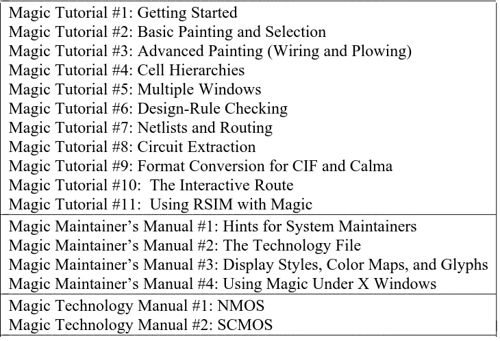
6.1 Magic Tutorial #1: Getting Started
6.2 Magic Tutorial #2: Basic Painting and Selection
6.3 Magic Tutorial #3: Advanced Painting (Wiring and Plowing) 6.4 Magic Tutorial #4: Cell Heirarchies
6.5 Magic Tutorial #5: Multiple Windows 6.6 Magic Tutorial #6: Design-Rule Checking 6.7 Magic Tutorial #7: Netlists and Routing 6.8 Magic Tutorial #8: Circuit Extraction
6.9 Magic Tutorial #9: Format Conversion for CIF and Calma 6.10 Magic Tutorial #10: The Interactive Router
6.11 Magic Tutorial #11: Using RSIM with Magic CHAPTER 7 Maintainer’s Manuals
7.1 Magic Maintainer’s Manual #1: Hints for System Maintainers 7.1 Magic Maintainer’s Manual #2: The Technology File
7.1 Magic Maintainer’s Manual #3: The Display Style and Glyph Files 7.1 Magic Maintainer’s Manual #4: Using Magic under X Windows CHAPTER 8 Technology Manuals
This document corresponds to Magic version 6.
1. Introduction
This version of Magic, version 6, gathers together work done by numerous people at several institutions since Magic version 4 was released from Berkeley on the 1986 VLSI tools tape. This is a release of Magic and IRSIM only. You’ll probably want to obtain other tools by ordering the 1986 VLSI Tools Tape from Berkeley.
This release has been prepared with the assistance of several groups. Much of the new software came from Walter Scott’s group at the Lawrence Livermore National Labs (LLNL). LLNL also provided partial funding to help prepare the release. Digital Equip-ment Corporation’s Western Research Lab (DECWRL) helped out by providing com-puter equipment, a place to work, and the services of one of us (Robert Mayo). Don Stark, Michael Arnold, and Gordon Hamachi also worked on the release at DECWRL. Stanford donated significant pieces of new code, including a simulation system called IRSIM. Other individuals and institutions have also contributed code and assistance in ways too numerous to detail here.
New features in Magic Version 6 include:
New and Improved Routing - Michael Arnold and Walter Scott of LLNL
Three major routing improvements have been made in this version of Magic. There is a new, improved, global router courtesy of Walter Scott (of LLNL). Walter Scott has also added a gate array router. See the "garoute" command in the manual page for details. Michael Arnold (of LLNL) has writ-ten an interactive maze router that allows the user to specify hints to control the routing. See the documentation for the "iroute" command.
Extractor Enhancements - Don Stark of Stanford and Walter Scott of LLNL
The new "extresis" command, developed by Don Stark, provides substan-tially better resistance extraction. Magic’s normal extraction ("extract") lumps resistances on a node into a single value. In branching networks, this approxi-mation is often not acceptable. Resis was written to solve this problem. Walter Scott added accurate path length extraction, an important feature when dealing with high speed circuits, such as ECL.
New contact structure - Walter Scott and Michael Arnold of LLNL and Don Stark of
Stanford
-Multilayer contacts are handled better. In the previous version of Magic, there needed to be a separate contact type for each possible combination of contact layers over a given point. This caused a combinatorial explosion of tile types for multi-layer technologies with stacked contacts. Under the new scheme, there are only a couple of tile types for each layer: one that connects up, one that connects down, and one that connects in both directions.
Simulator Interface to IRSIM - Stanford
A simulator interface is provided courtesy of Stanford. See the commands "startrsim", "simcmd", and "rsim". The irsim simulator, Stanford’s much improved rewrite of esim, is included in this distribution. Credit goes to Mike Chow, Arturo Salz, and Mark Horowitz.
New device/machine Support - Various
X11 is fully supported in this release, and is the preferred interface. Older drivers for graphics terminals and X10 are also included, but X11 is the preferred interface (meaning it is better supported and you’ll have lots of com-pany). Magic’s X11 driver has a long history, starting with an X10 driver by Doug Pan at Stanford. Brown University, the University of Southern Califor-nia, the University of Washington, and Lawrence Livermore National Labs all prepared improved versions, some of them for X11. Don Stark of Stanford took on the task of pulling these together and producing the X11 driver in this release.
Magic runs on a number of workstations, such as the DECstation 3100 and Sun’s SPARC processors. Partial Unix System V support is provided, via the compilation flags mentioned below. The system also runs on the MacII. Don Stark gets credit for the System V mods and support for HP machines, while Mike Chow helped get it running on the MacII.
To assist people with small machines (such as the Mac II), Magic can now be compiled without some of its fancy features. Compilation flags are provided, as indicated below, to eliminate things like routing, plotting, or calma output. This is courtesy of Don Stark.
Reorganization of Magic Source Directory
Magic, as previously distributed, was set up with the assumption that lots of people would be changing the code at the same time. As a result, the makefiles did all sorts of paranoid things like making extra copies of the source code whenever a module was re-installed.
Since Magic is more stable now, this copying is no longer needed. Instead, each makefile invokes the script ../:instclean after installing a module. This script, by default, doesn’t copy the source code but does leave the .o files around. This cuts down on the disk space needed by a factor of two. You can change the script if you want the copying, or if you want to delete unused .o files to save even more disk space.
Lots of bug fixes - Various
Lots of bugs have been fixed in this release. We’d like to thank every-body that has reported bugs in the past. If you find a new bug, please report it
-as mentioned below.
2. Distribution Information
This version of Magic is available via FTP. Contact "[email protected]" for infor-mation.
For a handling fee, this version of Magic may be obtained on magnetic tape from:
EECS/ERL Industrial Liaison Program 479 Cory Hall
University of California at Berkeley Berkeley, CA 94720
3. Bug Reports
Maintenance of Magic is a volunteer effort. Please send descriptions of bugs via InterNet e-mail to "[email protected]" or via Uucp e-mail to "decwrl!magic". If you develop a fix for the problem, please send that too!
4. Changes for Magic maintainers
Previous releases of Magic expected to find their system files in the home directory of the user cad. The default behavior of version 6 is no different, but it is possible to put the files in another directory by setting the CAD_HOME shell environment variable. If this variable is set, magic will use that location instead of the ∼cad it finds in the pass-word file.
4.1. INSTALLING MAGIC
The distribution tape contains a version of Magic ready to run on Digital’s line of Ultrix RISC workstations, such as the DECstation 3100. For other machines, read ahead. In any event, all users should set their shell environment variable CAD_HOME to point to the place where the tape is loaded, unless that place is∼cad, in which case things will default correctly.
Before installing Magic, you should set your shell environment variable CAD_HOME to point to the place where you loaded the tape. If you "cd" to the magic source directory (${CAD_HOME}/src/magic) you will find a makefile. A "make config" will run a configuration script that asks questions about your configuration and sets up magic to be compiled for your local environment.
After running a "make config", you can run a "make force" to force a complete recompilation of magic. A "make install" will then copy the binaries to the ${CAD_HOME}/bin area, as well as install things in ${CAD_HOME}/lib and ${CAD_HOME}/man.
Included in this documentation is a set of Magic maintainer’s manuals. These should be read by anybody interested in modifying Magic or by anybody that is having difficulty installing it on their system.
-4.2. Technology file changes
Users of Magic 4 should have little trouble switching to Magic 6.
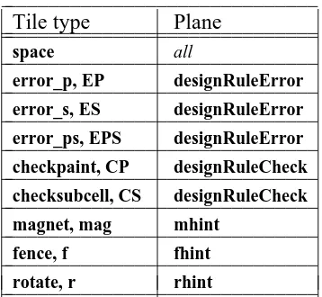
A new section, the mzrouter section needs to be added to your technology files. See the mzrouter section of the tutorial Magic Maintainer’s Manual #2: The Technology
File for details.
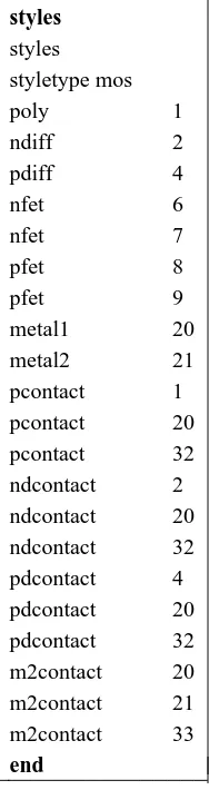
Display styles must be defined in the .tech file for the mzrouter hint layers magnet, fence and rotate. We suggest copying this information from the styles section of the scmos technology file on the distribution tape. You’ll also need to include these display styles in your .dstyle file.
5. Beta-test Sites
We’d like to thank the beta-test sites that tried out this version of Magic, reported bugs and fixes in a timely manner, and ported the code to new machines:
Mike Chow, Apple Computer Arun Rao, Arizona State University Richard Hughey, Brown University Rick Carley, Carnegie-Mellon University Hank Walker, Carnegie-Mellon University Christos Zoulas, Cornell University
Andreas Andreou, John Hopkins University
George Entenman, The Microelectronics Center of North Carolina Shih-Lien Lu, The MOSIS Service
Jen-I Pi, The MOSIS Service
Guntram Wolski, Silicon Engineering, Inc. Don Stark, Stanford University
Gregory Frazier, University of California at Los Angeles Yuval Tamir, University of California at Los Angeles Steven Parkes, University of Illinois
Larry McMurchie, University of Washington Tim Heldt, Washington State University David Lee, Xerox Palo Alto Research Center
Martin Harriman of Silicon Engineering wrote a "select less" command for Magic during the beta-test phase. "Select less" has been a much-requested feature.
In addition to the persons named above, there were many other beta-test users of Magic at these and other sites -- too many to list here. We appreciate their help. We also acknowledge the help of the pre-release sites, who tested a version that included most of the fixes from the beta-test phase.
-EXT2DLYS ( 1 ) CAD Tool User’s Manual EXT2DLYS ( 1 )
NAME
ext2dlys−create a SCALD wire-delays file from a tree of .ext files
SYNOPSIS
ext2dlys [−−d psPerPf ] [−−l psPerCentimicron ] [−−m minmult maxmult ] [−−o outfile ] [−−t capscale ] [
−−D drivefile ] [−−I iload ] [−−L netfile ] [−−M scaldmapfile ] [−−O oload ] [ extcheck-options ] file
DESCRIPTION
Ext2dlys is used to produce a SCALD wire-delays file (in dlys (5) format) on standard output, to be used in
simulation and timing verification. It computes the wire delay information from capacitance in the circuit extracted from a layout by magic (1).
The filename file given to ext2dlys is the name of the root .ext file of the extracted circuit, and also of the
.net file. The .ext files, in ext (5) format, contain the capacitance to substrate for each electrical node,
specify the connectivity of the circuit, and also give distance information. The .net file, in net (5) format, lists the nets and terminals in the circuit that will be present in the .dlys file. All terminals in the .net file are by default considered to be inputs (receivers) unless explicitly identified as drivers in the drivefile given with the−−D option; see the description below. In addition to identifying the terminals of interest, the .net
file gives the signal name associated with each net as a comment line immediately prior to the list of termi-nals in the net.
The remaining arguments to ext2dlys tell how this capacitance and distance information is to be converted into delay, as well as specifying the use of alternate files:
−−d psPerPf
Used to turn capacitance into delay; one picofarad is equal to psPerPf picoseconds of delay. The default value is 100.0, or roughly what one would expect if using 100 ohm drivers. The value of
psPerPf is used only for drivers whose effective on resistance hasn’t been given explicitly in the drivefile specified with the−−D flag (see below).
−−l psPerCentimicron
Used to turn distance into delay; one centimicron of distance is equal to psPerCentimicron picoseconds of delay.
−−m minmult maxmult
Multipliers to convert estimated delays into best-case (minmult) and worst-case (maxmult). Both are 1.0 by default.
−−o outfile
Write the output to outfile (note that no suffix is implied) instead of to the standard output.
−−t capscale
Gives a scale factor by which units of capacitance in the .sim file will be multiplied in order to give femtofarads. Capscale may be a real number; its default value is 1.0.
−−D drivefile
Also used to turn capacitance into delay, but on a per-net basis. Each line of the file drivefile con-sists of a hierarchical pin name (of an output driver) and its associated ‘‘drive factor’’ (equivalent to delay in the−−d flag above), namely the number of picoseconds per picofarad for the net driven
by that output pin. Nets driven by a pin listed not in this file use the default delay specified by−−d
above. If this file isn’t given, we don’t know for certain which pins are the drivers in each net, so we arbitrarily pick one pin per net and assume it is the driver.
−−I iload In addition to the capacitance reported in the .sim file for each net, add an additional iload
attofarads of capacitance for each input on a given net to the total capacitance for that net. (Inputs are counted only if they appear in the .net file.) The default value of iload is 0.0, since it varies so much from one technology to the next. This option is provided to account for extra transistor capacitance not computed by the extractor, such as when the technology of the circuit being extracted is non-MOS (e.g, bipolar).
EXT2DLYS ( 1 ) CAD Tool User’s Manual EXT2DLYS ( 1 )
−−L netfile
Instead of using file.net as the netlist file, use netfile.net instead.
−−M scaldmap
If specified, then scaldmap is read (note no suffix implied) to obtain a translation between Magic terminal names and SCALD pin names. Each line in scaldmap contains a Magic name followed by a SCALD name. The Magic name is terminated by the first blank; the SCALD name continues from the next non-blank character to the end of the line, possibly including embedded blanks. When writing the output file, the corresponding SCALD name is used instead of the Magic name for each pin in a net. See dlys (5) for more details of the output file format.
−−O oload
In addition to the capacitance reported in the .sim file for each net, add an additional oload attofarads of capacitance for each output on a given net to the total capacitance for that net. The default value of oload is 0.0. If only−−I and not−−O is specified, ext2dlys treats this as though both
−−I and−−O had been specified with the same values; inputs and outputs are not distinguished.
In addition, all of the options of extcheck (1) are accepted.
SEE ALSO
extcheck (1), ext2sim (1), ext2spice (1), magic (1), dlys (5), ext (5)
AUTHOR
Walter Scott
EXT2SIM ( 1 ) CAD Tool User’s Manual EXT2SIM ( 1 )
NAME
ext2sim−convert hierarchical ext (5) extracted-circuit files to flat sim (5) files
SYNOPSIS
ext2sim [−−a aliasfile ] [−−l labelsfile ] [−−o simfile ] [−−A ] [−−B ] [−−F ] [−−L ] [−−t ] [ extcheck-options ] [
-y num ] [ -f mit|lbl|su ] [ -J hier|flat ] [ -j device:sdRclass[/subRclass]/defaultSubstrate ] root
DESCRIPTION
Ext2sim will convert an extracted circuit from the hierarchical ext (5) representation produced by Magic to the flat sim (5) representation required by many simulation tools. The root of the tree to be extracted is the file root.ext; it and all the files it references are recursively flattened. The result is a single, flat representa-tion of the circuit that is written to the file root.sim, a list of node aliases written to the file root.al, and a list of the locations of all nodenames in CIF format, suitable for plotting, to the file root.nodes. The file
root.sim is suitable for use with programs such as crystal (1), esim (1), or sim2spice (1).
The following options are recognized:
−−a aliasfile Instead of leaving node aliases in the file root.al, leave it in aliasfile.
−−l labelfile Instead of leaving a CIF file with the locations of all node names in the file root.nodes, leave it in labelfile.
−−o outfile Instead of leaving output in the file root.sim, leave it in outfile.
−−A Don’t produce the aliases file.
−−B Don’t output transistor or node attributes in the .sim file. This option will also disable the output of information such as the area and perimeter of source and drain diffusion and the fet substrate. For compatibitlity reasons the latest version of ext2sim outputs this information as node attibutes. This option is necessary when preparing input for pro-grams that don’t know about attributes, such as sim2spice (1) (which is actually made obsolete by ext2spice (1), anyway), or rsim (1).
−−F Don’t output nodes that aren’t connected to fets (floating nodes).
−−L Don’t produce the label file.
−−tchar Trim characters from node names when writing the output file. Char should be either "#" or "!". The option may be used twice if both characters are desired.
−−f MIT|LBL|SU Select the output format. MIT is the traditional sim(5) format. LBL is a variant of it understood by gemini(1) which includes the substrate connection as a fourth terminal before length and width. SU is the internal Stanford format which is described also in
sim(5) and includes areas and perimeters of fet sources, drains and substrates.
−−y num Select the precision for outputing capacitors. The default is 1 which means that the capa-citors will be printed to a precision of .1 fF.
−−J hier|flat Select the source/drain area and perimeter extraction algorithm. If hier is selected then the areas and perimeters are extracted only within each subcell. For each fet in a subcell the area and perimeter of its source and drain within this subcell are output. If two or more fets share a source/drain node then the total area and perimeter will be output in only one of them and the other will have 0. If flat is selected the same rules apply only that the scope of search for area and perimeter is the whole netlist. In general flat (which is the default) will give accurate results (it will take into account shared sources/drains) but hier is provided for backwards compatibility with version 6.4.5. On top of this selec-tion you can individually control how a terminal of a specific fet will be extracted if you put a source/drain attribute. ext:aph makes the extraction for that specific terminal hierarchical and ext:apf makes the extraction flat (see the magic tutorial about attaching attribute labels). Additionaly to ease extraction of bipolar transistors the gate attribute
EXT2SIM ( 1 ) CAD Tool User’s Manual EXT2SIM ( 1 )
ext:aps forces the output of the substrate area and perimeter for a specific fet (in flat
mode only).
−−j device:sdRclass[/subRclass]/defaultSubstrate
Gives ext2sim information about the source/drain resistance class of the fet type device. Makes device to have sdRclass source drain resistance class, subRclass substrate (well) resistance class and the node named defaultSubstrate as its default substrate. The defaults are nfet:0/Gnd and pfet:1/6/Vdd which correspond to the MOSIS technology file but things might vary in your site. Ask your local cad administrator.
The way the extraction of node area and perimeter works in magic the total area and perimeter of the source/drain junction is summed up on a single node. That is why all the junction areas and perimeters are summed up on a single node (this should not affect simulation results however).
Special care must be taken when the substrate of a fet is tied to a node other than the default substrate (eg
in a bootstraping charge pump). To get the correct substrate info in these cases the fet(s) with separate wells should be in their own separate subcell with ext:aph attributes attached to their sensitive terminals (also all the transistors which share sensistive terminals with these should be in another subcell with the same attributes).
In addition, all of the options of extcheck (1) are accepted.
SCALING AND UNITS
If all of the .ext files in the tree read by ext2sim have the same geometrical scale (specified in the scale line in each .ext file), this scale is reflected through to the output, resulting in substantially smaller .sim files. Otherwise, the geometrical unit in the output .sim file is a centimicron.
Resistance and capacitance are always output in ohms and femptofarads, respectively.
SEE ALSO
extcheck (1), ext2dlys (1), ext2spice (1), magic (1), rsim (1), ext (5), sim (5)
AUTHOR
Walter Scott additions/fixes by Stefanos Sidiropoulos.
BUGS
Transistor gate capacitance is typically not included in node capacitances, as most analysis tools compute the gate capacitance directly from the gate area. The -c flag therefore provides a limit only on non-gate capacitance. The areas and perimeters of fet sources and drains work only with the simple extraction algorith and not with the extresis flow. So you have to model them as linear capacitors (create a special extraction style) if you want to extract parasitic resistances with extresis.
EXT2SPICE ( 1 ) CAD Tool User’s Manual EXT2SPICE ( 1 )
NAME
ext2spice−convert hierarchical ext (5) extracted-circuit files to flat spice files
SYNOPSIS
ext2spice [ −−B ] [ extcheck-options ] [ -M|m ] [ -y num ] [ -f hspice|spice3|spice2 ] [ -J hier|flat ] [ -j device:sdRclass[/subRclass]/defaultSubstrate ] root
DESCRIPTION
Ext2spice will convert an extracted circuit from the hierarchical ext (5) representation produced by Magic to a flat spice file which can be accepted by spice2, spice3, hspice and other simulation tools. The root of the tree to be extracted is the file root.ext; it and all the files it references are recursively flattened. The result is a single, flat representation of the circuit that is written to the file root.spice .
The following options are recognized:
−−o outfile Instead of leaving output in the file root.spice, leave it in outfile.
−−B Don’t output transistor or node attributes in the spice file. Usually the attributes of a node or a device are output as special comments **fetattr and **nodeatrr which can be processed further to create things such a initial conditions etc.
−−F Don’t output nodes that aren’t connected to fets (floating nodes). Normally capacitance from these nodes is output with the comment **FLOATING attached on the same line.
−−tchar Trim characters from node names when writing the output file. Char should be either "#" or "!". The option may be used twice if both characters are desired. Trimming "#" and "!" is enabled by default when the format is hspice.
-M|m Merge parallel fets. -m means conservative merging of fets that have equal widths only (usefull with hspice format multiplier if delta W effects need to be taken care of). -M means aggresive merging: the fets are merged if they have the same terminals and the same length.
−−y num Select the precision for outputing capacitors. The default is 1 which means that the capa-citors will be printed to a precision of .1 fF.
−−f hspice|spice2|spice3
Select the output format. Spice3 is the the format understood by the latest version of berkeley spice. Node names have the same names as they would in a sim(5) file and no special constructs are used. Spice2 is the format understood by the older version of spice (which usually has better convergence). Node names are numbers and a dictionary of number and corresponding node is output in the end. HSPICE is a format understood by meta-software’s hspice and other commercial tools. In this format node names cannot be longer than 15 characters long (blame the fortran code): so if a hierarchical node name is longer it is truncated to something like x1234/name where x1234 is an alias of the normal node hierarchical prefix and name its hierarchical postfix (a dictionary mapping prefixes to real hierarchical paths is output at the end of the spice file). If the node name is still longer than 15 characters long (again blame the fortran code) it is translated to something like z@1234 and the equivalent name is output as a comment. In addition since hspice supports scaling and multipliers so the output dimensions are in lambdas and if parallel fets are merged the hspice construct M is used.
−−J hier|flat Select the source/drain area and perimeter extraction algorithm. If hier is selected then the areas and perimeters are extracted only within each subcell. For each fet in a subcell the area and perimeter of its source and drain within this subcell are output. If two or more fets share a source/drain node then the total area and perimeter will be output in only one of them and the other will have 0. If flat is selected the same rules apply only that the scope of search for area and perimeter is the whole netlist. In general flat (which
EXT2SPICE ( 1 ) CAD Tool User’s Manual EXT2SPICE ( 1 )
is the default) will give accurate results (it will take into account shared sources/drains) but hier is provided for backwards compatibility with version 6.4.5. On top of this selec-tion you can individually control how a terminal of a specific fet will be extracted if you put a source/drain attribute. ext:aph makes the extraction for that specific terminal hierarchical and ext:apf makes the extraction flat (see the magic tutorial about attaching attribute labels). Additionaly to ease extraction of bipolar transistors the gate attribute
ext:aps forces the output of the substrate area and perimeter for a specific fet (in flat
mode only).
−−j device:sdRclass[/subRclass]/defaultSubstrate
Gives ext2sim information about the source/drain resistance class of the fet type device. Makes device to have sdRclass source drain resistance class, subRclass substrate (well) resistance class and the node named defaultSubstrate as its default substrate. The defaults are nfet:0/Gnd and pfet:1/6/Vdd which correspond to the MOSIS technology file but things might vary in your site. Ask your local cad administrator.
The way the extraction of node area and perimeter works in magic the total area and perimeter of the source/drain junction is summed up on a single node. That is why all the junction areas and perimeters are summed up on a single node (this should not affect simulation results however).
Special care must be taken when the substrate of a fet is tied to a node other than the default substrate (eg
in a bootstraping charge pump). To get the correct substrate info in these cases the fet(s) with separate wells should be in their own separate subcell with ext:aph attributes attached to their sensitive terminals (also all the transistors which share sensistive terminals with these should be in another subcell with the same attributes).
In addition, all of the options of extcheck (1) are accepted.
The awk filter spice2sim is provided with the current distribution for debugging purposes.
SEE ALSO
extcheck (1), ext2spice (1), magic (1), rsim (1), ext (5), sim (5)
AUTHOR
Stefanos Sidiropoulos.
BUGS
The areas and perimeters of fet sources and drains work only with the simple extraction algorith and not with the extresis flow. So you have to model them as linear capacitors (create a special extraction style) if you want to extract parasitic resistances with extresis.
EXTCHECK ( 1 ) CAD Tool User’s Manual EXTCHECK ( 1 )
NAME
extcheck − check hierarchical ext (5) files for global node connectivity and summarize number of fets, nodes, etc.
SYNOPSIS
extcheck [−−c cthresh ] [−−p path ] [−−r rthresh ] [−−s sym=value ] [−−C ] [−−R ] [−−S symfile ] [−−T tech ]
root
DESCRIPTION
Extcheck will read an extracted circuit in the hierarchical ext (5) representation produced by Magic, check
to ensure that all global nodes (those to which a label ending in an exclamantion point is attached) are fully connected in the layout, and then print a count of the number of various items (nodes, fets, etc) encountered while flattening the circuit. The root of the tree to be processed is the file root.ext; it and all the files it references are recursively flattened.
The following options are recognized:
−−c cthresh
Set the capacitance threshold to cthresh femtofarads. Extcheck will count the number of explicit internodal capacitors greater than cthresh, the number of nodes whose capacitance is greater than
cthresh, as well as the total number of nodes. (Other programs such as ext2sim (1) use this option
as a threshold value below which a capacitor will not be output). The default value for cthresh is 10 femtofarads.
−−p path Normally, the path to search for .ext files is determined by looking for path commands in first
∼cad/lib/magic/sys/.magic, then∼/.magic, then .magic in the current directory. If−−p is specified,
the colon-separated list of directories specified by path is used instead. Each of these directories is searched in turn for the .ext files in a design.
−−r rthresh
Set the resistance threshold to rthresh ohms. Similar in function to−−c, but for resistances. The
default value for rthresh is 10 ohms.
−−s sym=value
It’s possible to use special attributes attached to transistor gates to control the length and width of transistors explicitly, rather than allowing them to be determined by the extractor. These attri-butes are of the form ext:w=widthˆ or ext:l=lengthˆ, where width or length can either be numeric, or textual. (The trailing ‘‘ˆ’’ indicates that these are transistor gate attributes). If textual, they are treated as symbols which can be assigned a numeric value at the time ext2sim is run. The−−s flag
is used to assign numeric values to symbols. If a textual symbol appears in one of the above attri-butes, but isn’t given a numeric value via −−s (or −−S below), then it is ignored; otherwise, the
transistor’s length or width is set to the numeric value defined for that symbol. (This option is not
currently used by extcheck, but it is common to ext2sim (1) and other tools that are written using the extflat (3) library)
−−C Set the capacitance threshold to infinity. Because this avoids any internodal capacitance process-ing, all tools will run faster when this flag is given.
−−R Set the resistance threshold to infinity.
−−S symfile
Each line in the file symfile is of the form sym=value, just like the argument to the−−s flag above;
the lines are interpreted in the same fashion. (This option is not currently used by extcheck, but it
is common to ext2sim et. al.)
−−T tech Set the technology in the output .sim file to tech. This overrides any technology specified in the
root .ext file.
EXTCHECK ( 1 ) CAD Tool User’s Manual EXTCHECK ( 1 )
SEE ALSO
ext2dlys (1), ext2sim (1), ext2spice (1), magic (1), rsim (1), sim2spice (1), ext (5), sim (5)
AUTHOR
Walter Scott
BUGS
The−−s mechanism is incomplete; it should allow quantities other than transistor lengths and widths to be
specified.
FSLEEPER ( 1 ) CAD Tool User’s Manual FSLEEPER ( 1 )
NAME
fsleeper−run sleeper remotely
SYNOPSIS
fsleeper [−−t tty ] [−−l user ] [ remotemachine ]
DESCRIPTION
Fsleeper is used if you wish to run a program such as magic (1) on a different machine (remotemachine)
than the one to which a graphics terminal is attached, and the local graphics terminal has no login process. Normally, fsleeper will start a remote sleeper on the companion graphics terminal for your terminal. This graphics terminal is found by looking in the file ∼cad/lib/displays, as described in displays (5). If a dif-ferent graphics terminal is desired, it may be specified by the -t flag. Note that this is the terminal on the local machine, not the remote machine. (The remote terminal will be printed by sleeper (1) when it starts up on the remote machine).
Also, normally fsleeper will attempt to log in as the user sleeper on the remote machine. If a different user name is desired, it may be specified with the -l flag. This user name must exist on remotemachine.
FILES
∼cad/lib/displays
SEE ALSO
magic(1), rsleeper(1), sleeper(1), displays(5)
AUTHOR
Walter Scott
BUGS
If no remotemachine is specified, it defaults to ucbkim. This is fine for Berkeley, but useless elsewhere.
GRSUNPROG ( 1 ) CAD Tool User’s Manual GRSUNPROG ( 1 )
NAME
grSunProg−internal process for Magic’s Sun 120 display driver
SYNOPSIS
grSunProg colorWindowName textWindowName notifyPID requestFD pointFD buttonFD
DESCRIPTION
GrSunProg is an internal program used by Magic when using the Sun 120 workstation’s display. This manual page is intended only for Magic maintainers.
GrSunProg collects button pushes from the color window and sends them over a pipe to Magic. The pro-gram also responds to requests from Magic for the mouse position. In addition, this propro-gram tells Suntools to forward characters typed in the color window directly to Magic’s text window.
ARGUMENTS
All six arguments are required:
colorWindowName
This is the name of the color window that magic is running under (such as /dev/win3). Magic normally opens up the color monitor with a single, large, window on it.
textWindowName
This is the name of the text window that contains Magic’s command log. Keyboard events are forwarded to this window.
notifyPID
If this processID is not 0, then SIGIO signals are sent to this process when there is data for it.
requestFD pointFD buttonFD
These are the file descriptors that grSunProg should use in its interface (see below). They are small integers printed as strings.
INTERFACE
Button pushes are sent out over file descriptor buttonFD. A button push is encoded as two characters fol-lowed by two integers giving the location of the button push. The first character is either ’L’, ’M’, or ’R’ depending on the button pushed: Left, Middle, or Right. The next character is either ’D’ or ’U’ depending on the action: Up or Down. The two numbers are the X and Y coordinates of the button push. This string is followed by a newline. Example: LD 123 342 means that the left button was pushed down at location (123, 342).
GrSunProg sometimes receives a character from Magic over file descriptor requestFD. If this character is an EOF, then the program terminates. If this character is an ’A’, then grSunProg responds with a ’P’ and the current mouse coordinates over file descriptor pointFD. This string is followed by a newline. Example:
P 101 23 means that the mouse is currently at location (101, 23).
SEE ALSO
magic(1) grsunprog2(1)
AUTHOR
Robert N. Mayo
MAGIC ( 1 ) CAD Tool User’s Manual MAGIC ( 1 )
NAME
magic−VLSI layout editor
SYNOPSIS
magic [−−T technology ] [−−d device_type ] [−−g graphics_port ] [−−m monitor_type ] [−−i tablet_port ] [
−−D ] [−−F object_file save_file ] [ file ]
DESCRIPTION
Magic is an interactive editor for VLSI layouts that runs under 4.3 BSD Unix, as well as derivatives such as Digital’s Ultrix and Sun’s SunOS. This man page is a reference manual; if you are a first-time user, you should use the Magic tutorials in ‘‘The 1989 Livermore/DEC-WRL Magic Release’’ to get acquainted with the system.
Magic runs in two different configurations. For workstations with an integrated color display, one window of the screen is used to display text (commands and Magic’s responses) and other windows are used for displaying layouts in color. In older systems using serial-line terminals, Magic uses two terminals: one for text and a separate color display for displaying layouts. In these systems you should run Magic from the text display.
Normally, Magic is run under a window system such as X11 (preferred) or Sun Tools. The command line switch "-d" can be used to tell Magic which kind of window system you are running, although Magic is pretty good at guessing. When using serial-line terminals, the "-d", "-g", and "-i" switches can be used, and the file∼cad/lib/displays should be created by the system administrator (see DISPLAYS(5) manual page). Here are the options accepted by Magic:
−−T The next argument is the name of a technology. The tile types, display information, and design rules for this technology are read by Magic from a technology file when it starts up. The technol-ogy defaults to ‘‘scmos’’.
−−d The next argument is the type of workstation or graphics display being used. Magic supports these types:
NULL A null device for running Magic without using a graphics display.
X11 X-windows, version 11 release 3. The is the preferred interface. Magic acts as a client to the X window server and interfaces to all graphics terminals supported by the X server. The window manager must be configured to pass mouse buttons, without interpretation, to clients. It is recommended that the meta key be used with mouse buttons to communi-cate requests to the window manager. Standard window manager commands manipulate Magic windows.
Addition information on Magic’s X11 driver, including options for .Xdefaults files, may be found in ‘‘Magic Maintainer’s Manual #4: Using Magic Under X Windows’’.
X10 An X driver for X version 10. Currently not used much, and being phased out.
XWIND
Simply another name for either the X11 driver or the X10 driver. This is normally set to refer to whichever driver is more popular at a given site. This is here mostly for back-ward compatibility reasons.
The following drivers are used on Suns when X is not available.
SUN60 A Sun Microsystems workstation model Sun3/60C. (May work for Sun4/60C, also.)
The Sun60 display is the same as a Sun110 display, as far as Magic is concerned.
SUN110
A Sun Microsystems workstation, model Sun3/110C (color display). You must be run-ning Suntools. This is virtually identical to the SUN160 display type below. May also work for Sun4/110C.
MAGIC ( 1 ) CAD Tool User’s Manual MAGIC ( 1 )
SUN160
A Sun 160 workstation with a single screen that has 8 bit-planes of color. You must be running Suntools in order for Magic to run with this option. Also, you can not resize or redisplay Magic windows while Magic is collecting a command (since Magic is only one process). Because Sun’s window package doesn’t do interrupt processing, you can’t interrupt Magic unless you point to its text window.
SUNBW
A black & white Sun workstation. Because this system only has one bit-plane, Magic does extra redisplay whenever it erases the box or highlight areas. Also, it is hard to see all the layers since they are drawn as stippled areas instead of colored areas. You must be running Suntools in order for Magic to run with this option, and the caveats for the SUN160 version also apply to this version.
The following drivers are available, but are seldom used and thus may be in disrepair.
UCB512
An old AED512 with the Berkeley microcode ROMs and an attached bitpad (Summa-Graphics Bitpad One). The ROMs are available from AED.
UCB512N
A new "Colorware" AED512 with the Berkeley microcode ROMs and an attached bitpad (SummaGraphics Bitpad One). The ROMs are available from AED. We do not recom-mend the GTCO bitpad, since we have heard that their Summagraphics emulation mode can’t handle up/down button encoding nor double button pushes.
AED767
An AED767 with a SummaGraphics Mouse. Because of missing features in this device, programmable cursors and Bit-Blt do not work. Many thanks to Norm Jouppi and DECWRL for porting Magic to this device.
UCB1024
An AED1024 with a SummaGraphics Mouse and AED’s Magic microcode ROMs that implement the same operations as the UCB512 ROMs. Thanks to LSI Logic for this port.
AED1024
An AED1024 with a SummaGraphics Mouse and rev. D roms. Because of missing features in this device, programmable cursors do not work. Many thanks to Peng Ang and LSI Logic Corp. for porting Magic to this device.
other AEDs
Other AEDs can be handled by modifying Magic’s file grAed1.c. There are just too many combinations of options for AEDs for us to be able to supply drivers for all of them.
SUN120
A Sun Microsystems workstation, model Sun2/120 with the SunColor option (/dev/cgone0) and the Sun optical mouse. Also works on some old Sun1s with the ‘Sun2 brain transplant’. You must be running Suntools on the black and white display.
If no device is specified, Magic tries to guess which driver is appropriate (by checking the environment variables and by poking around in /dev). Types listed in∼cad/lib/displays override the default type.
−−g The next argument is the name of the device to use for communication with the graphics display. This is usually of the form /dev/ttyxx (for displays connected by RS232 lines, such as the AED family) or for some workstations, the name of the frame buffer device.
−−m The next argument is used to select the right color map for the monitor’s phosphors. ‘‘Std’’ works well for most monitors. This option is seldom used anymore, now that monitors are manufactured
MAGIC ( 1 ) CAD Tool User’s Manual MAGIC ( 1 )
with more consistent phosphors.
−−i The next argument is the name of the port to use for input from the tablet. This defaults to what-ever port is being used for the graphics output, and thus only needs to be specified under unusual circumstances. Only used for serial-line graphics terminals, not workstations.
−−D (System maintainers only). Run Magic in ‘‘debug’’ mode. This is intended for use with debuggers such as dbx (1) which would otherwise catch the SIGIO signal that is sent to Magic on each keystroke. When running Magic in debug mode, keystrokes and mouse clicks won’t inter-rupt the background design-rule checker, so it’s generally best to run with design-rule checking disabled (:drc off). When -D is set, crashes do not generate mail to the system maintainer and coredumps are not created.
−−F (This switch only works on VAXes, and hasn’t been tested recently.) The next two arguments are filenames. The first, object_file, is the name of the file that was executed to run this version of Magic. The second, save_file, is the name of a new file. After performing all initializations (read-ing in the technology file, load(read-ing the style information and colormap, etc), an executable image of Magic is stored in save_file. This executable image may then be run as a normal Magic, except that it starts up much more quickly. The symbol table from object_file is copied to save_file so the new version can be debugged.
When Magic starts up it looks for a command file in∼cad/lib/magic/sys/.magic and processes it if it exists. Then Magic looks for a file with the name ‘‘.magic’’ in the home directory and processes it if it exists. Finally, Magic looks for a .magic file in the current directory and reads it as a command file if it exists. The .magic file format is described under the source command.
COMMANDS -- GENERAL INFORMATION
Magics uses three sorts of commands. Pressing a mouse button is one sort of command. You can also enter commands by typing a : or ; character followed by the text of the command. Multiple commands may be specified on one line by separating them with semicolons. The third command form consists of single-letter abbreviations called ‘‘macros’’; macros are invoked by pressing single keys without typing a : first. Certain macros are predefined in the systemwide∼cad/lib/magic/sys/.magic file, but you can override them and add your own macros using the macro command (described below under COMMANDS FOR ALL WINDOWS).
Most commands deal with the window underneath the cursor, so if a command doesn’t do what you expect make sure that you are pointing to the correct place on the screen. There are several different kinds of win-dows in Magic (layout, color, and netlist); each window has a different command set, described in a separate section below.
MOUSE BUTTONS FOR LAYOUT WINDOWS
Magic uses a three button mouse. The buttons are interpreted in a way that depends on the current tool, as indicated by the shape of the cursor (see the tool command). The various tools are described below. The initial tool is box. These interpretations apply only when mouse buttons are pressed in the interior of a lay-out window.
Box Tool
This is the default tool, and is indicated by a crosshair cursor. It is used to position the box and to paint and erase:
left This button is used to move the box by one of its corners. Normally, this button picks up the box by its lower-left corner. To pick the box up by a different corner, click the right button while the left button is down. This switches the pick-up point to the corner nearest the cursor. When the button is released, the box is moved to position the corner at the cursor location. If the box has been set to snap to the window’s grid (see the :snap command), then the box corner is left aligned with the grid that the user has chosen for
MAGIC ( 1 ) CAD Tool User’s Manual MAGIC ( 1 )
the window with the :grid command, even if that grid is not visible.
right Change the size of the box by moving one corner. Normally this button moves the upper-right corner of the box. To move a different corner, click the left button while the right button is down. This switches the corner to the one nearest the cursor. When you release the button, three corners of the box move in order to place the selected corner at the cursor location (the corner opposite the one you picked up remains fixed). Snapping to the window’s grid is handled as for the left button.
middle (bottom)
Used to paint or erase. If the crosshair is over paint, then the area of the box is painted with the layer(s) underneath the crosshair. If the crosshair is over white space, then the area of the box is erased.
Wiring Tool
The wiring tool, indicated by an arrow cursor, is used to provide an efficient interface to the wir-ing commands:
left Same as the long command wire type.
right Same as the long command wire leg.
middle (bottom)
Same as the long command wire switch.
Netlist Tool
This tool is used to edit netlists interactively. It is indicated by a thick box cursor.
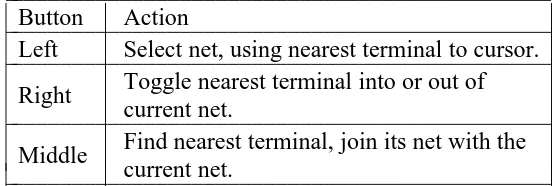
left Select the net associated with the terminal nearest the cursor.
right Find the terminal nearest the cursor, and toggle it into the current net (if it wasn’t already in the current net) or out of the current net (if it was previously in the net).
middle (bottom)
Find the terminal nearest the cursor, and join its net with the current net.
Rsim Tool
Used when running the IRSIM simulator under Magic. A pointing hand is used as the cursor.
left Moves the box just like the box tool.
right Moves the box just like the box tool.
middle (bottom)
Displays the Rsim node values of the selected paint.
LONG COMMANDS FOR LAYOUT WINDOWS
These commands work if you are pointing to the interior of a layout window. Commands are invoked by typing a colon (‘‘:’’) or semi-colon (‘‘;’’), followed by a line containing a command name and zero or more parameters. In addition, macros may be used to invoke commands with single keystrokes. Useful default macros are set in the global .magic file (in∼∼cad/lib/magic/sys unless the CAD_HOME
environ-ment variable is set). You can list all current macros with the macro command, described under ‘‘LONG COMMANDS FOR ALL WINDOWS’’. Unique abbreviations are acceptable for all keywords in com-mands. The commands are:
addpath searchpath
Add more directories to the end of Magic’s cell search path. See the documentation for the path command for an explanation of the search path.
array xsize ysize
Make many copies of the selection. There will be xsize instances in the x-direction and ysize instances in the y-direction. Paint and labels are arrayed by copying them. Subcells are not copied, but instead each instance is turned into an array instance with elements numbered from 0
MAGIC ( 1 ) CAD Tool User’s Manual MAGIC ( 1 )
to xsize-1 in the x-direction, and from 0 to ysize-1 in the y-direction. The spacing between ele-ments of the array is determined by the box x- and y-dimensions.
array xlo ylo xhi yhi
Identical to the form of array above, except that the elements of arrayed cells are numbered left-to-right from xlo to xhi and bottom-to-top from ylo to yhi. It is legal for xlo to be greater than xhi, and also for ylo to be greater than yhi.
box [args]
Used to change the size of the box or to find out its size. There are several sorts of arguments that may be given to this command:
(No arguments.)
Show the box size and its location in the edit cell, or root cell of its window if the edit cell isn’t in that window.
direction [distance]
Move the box distance units in direction, which may be one of left, right, up, or down.
Distance defaults to the width of the box if direction is right or left, and to the height of
the box if direction is up or down.
width [size] height [size]
Set the box to the width or height indicated. If size is not specified the width or height is reported.
x1 y1 x2 y2
Move the box to the coordinates specified (these are in edit cell coordinates if the edit cell is in the window under the cursor; otherwise these are in the root coordinates of the window). x1 and y1 are the coordinates of the lower left corner of the box, while x2 and
y2 are the upper right corner. The coordinates must all be integers.
calma [option] [args]
This command is used to read and write files in Calma GDS II Stream format (version 3.0, corresponding to GDS II Release 5.1). This format is like CIF, in that it describes physical mask layers instead of Magic layers. In fact, the technology file specifies a correspondence between CIF and Calma layers. The current CIF output style (see cif ostyle) controls how Calma stream layers are generated from Magic layers. If no arguments are given, the calma command generates a Calma stream file for the layout in the window beneath the cursor in file.strm, where file is the name of the root cell. This stream file describes the entire cell hierarchy in the window. The name of the library is the same as the name of the root cell. Option and args may be used to invoke one of several additional operations:
calma flatten
Ordinarily, Magic arrays are output using the Calma ARRAY construct. After a calma
flatten command, though, arrays will be output instead as a collection of individual cell
uses, as occurs when writing CIF.
calma help
Print a short synopsis of all of the calma command options.
calma labels
Output labels whenever writing a Calma output file.
calma lower
Allow both upper and lower case to be output for label text. This is the default behavior;
calma nolower causes lower case to be converted to upper case on output. calma noflatten
MAGIC ( 1 ) CAD Tool User’s Manual MAGIC ( 1 )
Undoes the effect of a prior :calma flatten command, re-enabling the output of Magic arrays using the Calma ARRAY construct.
calma nolabels
Don’t output labels when writing a Calma output file.
calma nolower
Convert lower to upper case when outputting labels.
calma read file
The file file.strm is read in Calma format and converted to a collection of Magic cells. The current CIF input style determines how the Calma layers are converted to Magic layers. The new cells are marked for design-rule checking. Calma format doesn’t iden-tify the root of the collection of cells read in, so none of the cells read will appear on the display; use load to make them visible. If the Calma file had been produced by Magic, then the name of the root cell is the same as the library name printed by the :calma read command.
calma write fileName
Writes a stream file just as if no arguments had been entered, except that the output is written into fileName.strm instead of using the root cell name for the file name.
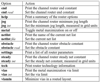
channels
This command will run just the channel decomposition part of the Magic router, deriving channels for the area under the box. The channels will be displayed as outlined feedback areas over the edit cell.
cif [option] [args]
Read or write files in Caltech Intermediate Form (CIF). If no arguments are given, this command generates a CIF file for the window beneath the cursor in file.cif, where file is the name of the root cell. The CIF file describes the entire cell hierarchy in the window. Option and args may be used to invoke one of several additional CIF operations:
cif arealabels [yes|no]
Enables/disables the cif area-label extension. If enabled, area labels are written via the
95 cif extension. If disabled, labels are collapsed to points when writing cif and the 94
cif construct is used. Area-labels are disabled by default (many programs don’t under-stand cif area-labels).
cif help Print a short synopsis of all of the cif command options. cif istyle [style]
Select the style to be used for CIF input. If no style argument is provided, then Magic prints the names of all CIF input styles defined in the technology file and identifies the current style. If style is provided, it is made the current style.
cif ostyle [style]
Select the style to be used for CIF output. If no style argument is provided, then Magic prints the names of all CIF output styles defined in the technology file and identifies the current style. If style is provided, it is made the current style.
cif read file
The file file.cif is read in CIF format and converted to a collection of Magic cells. The current input style determines how the CIF layers are converted to Magic layers. The new cells are marked for design-rule checking. Any information in the top-level CIF cell is copied into the edit cell. Note: this command is not undo-able (it would waste too much space and time to save information for undoing).
cif see layer
In this command layer must be the CIF name for a layer in the current output style.
MAGIC ( 1 ) CAD Tool User’s Manual MAGIC ( 1 )
Magic will display on the screen all the CIF for that layer that falls under the box, using stippled feedback areas. It’s a bad idea to look at CIF over a large area, since this com-mand requires the area under the box to be flattened and therefore is slow.
cif statistics
Prints out statistics gathered by the CIF generator as it operates. This is probably not useful to anyone except system maintainers.
cif write fileName
Writes out CIF just as if no arguments had been entered, except that the CIF is written into fileName.cif instead of using the root cell name for the file name. The current output style controls how CIF layers are generated from Magic layers.
cif flat fileName
Writes out CIF as in the cif write command, but flattens the design first (e.g. creates an internal version with the cell hierarchy removed). This is useful if one wishes to use the
and-not feature of the CIF output styles, but is having problems with interactions of
overlapping cells.
clockwise [degrees]
Rotate the selection by 90, 180 or 270 degrees. After the rotation, the lower-left corner of the selection’s bounding box will be in the same place as the lower-left corner of the bounding box before the rotation. Degrees defaults to 90. If the box is in the same window as the selection, it is rotated too. Only material in the edit cell is affected.
copy [direction [amount]] copy to x y
If no arguments are given, a copy of the selection is picking up at the point lying underneath the box lower-left corner, and placed so that this point lies at the cursor position. If direction is given, it must be a Manhattan direction (e.g. north, see the ‘‘DIRECTIONS’’ section below). The copy of the selection is moved in that direction by amount. If the box is in the same window as the selection, it is moved too. Amount defaults to 1. The second form of the command behaves as though the cursor were pointing to (x, y) in the edit cell; a copy of the selection is picked up by the point beneath the lower-left corner of the box and placed so that this point lies at (x, y).
corner direction1 direction2 [layers]
This command is similar to fill, except that it generates L-shaped wires that travel across the box first in direction1 and then in direction2. For example, corner north east finds all paint under the bottom edge of the box and extends it up to the top of the box and then across to the right side of the box, generating neat corners at the top of the box. The box should be at least as tall as it is wide for this command to work correctly. Direction1 and direction2 must be Manhattan direc-tions (see the section DIRECTIONS below) and must be orthogonal to each other. If layers is specified then only those layers are used; otherwise all layers are considered.
delete Delete all the information in the current selection that is in the edit cell. When cells are deleted, only the selected use(s) of the cell is (are) deleted: other uses of the cell remain intact, as does the disk file containing the cell. Selected material outside the edit cell is not deleted.
drc option [args]
This command is used to interact with the design rule checker. Option and args (if needed) are used to invoke a drc command in one of the following ways:
drc catchup
Let the checker process all the areas that need rechecking. This command will not return until design-rule checking is complete or an interrupt is typed. The checker will run even if the background checker has been disabled with drc off.
drc check
MAGIC ( 1 ) CAD Tool User’s Manual MAGIC ( 1 )
Mark the area under the box for rechecking in all cells that intersect the box. The recheck will occur in background after the command completes. This command is not normally necessary, since Magic automatically remembers which areas need to be rechecked. It should only be needed if the design rules are changed.
drc count
Print the number of errors in each cell under the box. Cells with no errors are skipped.
drc find [nth]
Place the box over the nth error area in the selected cell or edit cell, and print out infor-mation about the error just as if drc why had been typed. If nth isn’t given (or is less than 1), the command moves to the next error area. Successive invocations of drc find cycle through all the error tiles in the cell. If multiple cells are selected, this command uses the upper-leftmost one. If no cells are selected, this command uses the edit cell.
drc help
Print a short synopsis of all the drc command options.
drc off Turn off the background checker. From now on, Magic will not recheck design rules
immediately after each command (but it will record the areas that need to be rechecked; the command drc on can be used to restart the checker).
drc on Turn on the background checker. The checker will check whatever modifications have
not already been checked. From now on, the checker will reverify modified areas as they result from commands. The checker is run in the background, not synchronously with commands, so it may get temporarily behind if massive changes are made.
drc printrules [file]
Print out the compiled rule set in file, or on the text terminal if file isn’t given. For system maintenance only.
drc rulestats
Print out summary statistics about the compiled rule set. This is primarily for use in writ-ing technology files.
drc statistics
Print out statistics kept by the design-rule checker. For each statistic, two values are printed: the count since the last time drc statistics was invoked, and the total count in this editing session. This command is intended primarily for system maintenance pur-poses.
drc why
Recheck the area underneath the box and print out the reason for each violation found. Since this command causes a recheck, the box should normally be placed around a small area (such as an error area).
dump cellName [child refPointC] [parent refPointP]
Copy the contents of cell cellName into the edit cell so that refPointC in the child is positioned at point refPointP in the edit cell. The reference points can either be the name of a label, in which case the lower-left corner of the label’s box is used as the reference point, or as a pair of numbers giving the (x, y) coordinates of a point explicitly. If refPointC is not specified, the lower-left corner of cellName cell is used. If refPointP is not specified, the lower-left corner of the box tool is used (the box must be in a window on the edit cell). After this command completes, the new information is selected.
edit Make the selected cell the edit cell, and edit it in context. The edit cell is normally displayed in brighter colors than other cells (see the see command to change this). If more than one cell is selected, or if the selected cell is an array, the cursor position is used to select one of those cells as the new edit cell. Generally, Magic commands modify only the current edit cell.