ISSN: 1992-8645 www.jatit.org E-ISSN: 1817-3195
HONEYPOT BASED INTRUSION MANAGEMENT SYSTEM:
FROM A PASSIVE ARCHITECTURE TO AN IPS SYSTEM
1ELMEHDI BENDRISS, 2BOUBKER REGRAGUI
1SI3M, ENSIAS 2 SI3M, ENSIAS
E-mail: [email protected] , [email protected]
ABSTRACT
In this paper, we are presenting an Intrusion Prevention System (IPS) based on multiple sensors in the network. These sensors are in fact honeypots built using honeyd. Honeyd is a high level honeypot which is very light and which is offering a lot of possibilities to get the most of information gathered about attackers in general. In fact, we are presenting a solution to go from passive and isolated sensors to a collaborative platform to help prevent intrusions by analyzing all collected data. To be able to do this, honeyd2db module was developed to enable honeyd to log its data into a database instead of a local file to the sensor. This aggregation of data from all sensors give us the possibility to analyze all collected logs as a hole and come out with a decision (deny network traffic on a firewall for example) using any of the known methods of data analysis.
Keyword: Intrusion Prevention System (IPS), Honeypots, Honeyd, Network Sensors, Distributed System
1. INTRODUCTION
In nowadays, Intrusion Prevention has become more important than intrusion detection, as at this level, if an intrusion is already made into a network, the network, data, business …etc. are already at risk. Many vendors are trying to build their “in the box” IPS system, but as it is a “black box” in general, security admins are not very confident of what kind of behavior they’ll have to deal with. In our study we are trying to change an open source honeypot tool, which is Honeyd, and come out with an IPS system which is efficient and open enough to suite all needs.
The development of honeyd started on 2003. It is a high level honeypot, which means that it does only use scripts to emulate regular services (FTP, IIS, router shell, Unix shell…etc) versus low level honeypots that emulate an entire operating system. This makes it easy to extend to whatever service we need to monitor in real life. In fact, any use of a service offered by a honeypot sensor means an attack, as this sensor will never be presented as a public service available for every normal user. From another hand, honeyd is powerful enough to simulate complex networks and be integrated into real networks without and drawbacks to real servers’ usage.
As said in the Abstract, many vendors have their in the box IPS solution, and here we are presenting a new IPS based on honeyd that will give more freedom to the security administrator to set decision method, add or remove sensors without impact on results. Of course, the more sensors we have in a network the more data we may gather, and thus less chances to have “false positive”.
For the method of decision, we will stick to a basic method, which is based on thresholds, but as said, the architecture is open enough to change decision method without any change on other parts of the IPS.[1]
2. IPS ARCHITECTURE
ISSN: 1992-8645 www.jatit.org E-ISSN: 1817-3195
Figure 1. Logs to DB scheduled task
This solution gave as a good proof of concept and from this point the module honeyd2db was developed to patch Honeyd source code to add direct logging to database, which happens to be more suitable for real-time need.
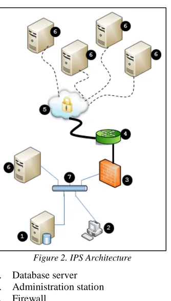
[image:2.612.92.292.72.259.2]The final IPS architecture is shown below:
Figure 2. IPS Architecture
1. Database server 2. Administration station 3. Firewall
4. Router
5. Internet, all network traffic between elements is encrypted
6. Honeyd based sensors 7. Internal LAN.
Sensors can be placed anywhere in the network, inside or outside the organization in case of multisite network for example. OpenVPN is used to link all sensors to the central server so that all network flow will be encrypted end-to-end.
[image:2.612.114.281.359.653.2]An additional DB server, not shown in the figure, can be used in a cluster mode to allow high availability of the database. If it is not the case, and in case of DB failure, all sensors must store logs locally until DB is back online. From another hand, the attacker cannot “see” the virtual IP of the VPN so the sensors, based on Linux, will be only reachable using SSH protocol on their VPN interface from central server. So there’s no way the attacker can get inside the server.
3. HONEYD2DB MODULE
By default Honeyd stores all its logs to a plain text file on the server it is running on. The need of having all data in the same place is obvious if we need to analyze, correlate and come out with a decision for the IPS. So the idea is to have a hook in the logging function of honeyd that will redirect all logs to a DB instead of the file if the module is enabled.
This can be schematized as shown in the following diagram:
Figure 3. Honeyd2DB Module
The basic DB design is based on Honeyd logfiles structure. An excerpt of what a logfile looks like is shown on next page:
Honeyd Framework
Events Logging function
Local plain-text log file Store logs
in DB
Is DB Available
Yes
H
O
NE
YD
2
[image:2.612.321.535.434.617.2]ISSN: 1992-8645 www.jatit.org E-ISSN: 1817-3195
2006-10-08 04:53:40 +0000: mydoom.pl[31476]: connection from 217.159.217.218:45771 to 192.168.2.1:1080
2006-10-08 04:53:40 +0000: mydoom.pl[31476]: socks4 connect request: dst host: 217.159.217.218, dst port: 25 2006-10-08 04:53:42 +0000: mydoom.pl[31477]: connection from 217.159.217.218:45956 to 192.168.2.1:1080
2006-10-08 04:53:42 +0000: mydoom.pl[31477]: unknown command: 0x05 0x01 0x00
2006-10-08 04:54:02 +0000: mydoom.pl[31478]: connection from 217.159.217.218:48324 to 192.168.2.1:1080
2006-10-08 04:54:02 +0000: mydoom.pl[31478]: socks4 connect request: dst host: 217.159.217.218, dst port: 25 2006-10-08 04:54:03 +0000: mydoom.pl[31479]: connection from 217.159.217.218:48502 to 192.168.2.1:1080
2006-10-08 04:54:03 +0000: mydoom.pl[31479]: unknown command: 0x05 0x01 0x00
2006-10-08 04:54:24 +0000: mydoom.pl[31480]: connection from 217.159.217.218:50970 to 192.168.2.1:1080
Most important fields are: • Timestamp
• IP of connection source
• Port number of connection source • IP of destination
• Port number of the destination service. • The payload of the log
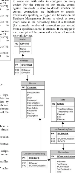
As we aim to centralize many sensors’ logs, some columns and management tables are added to handle all sensors and be able to query data by sensor or any other criteria. For the DBMS choice, to stay in the Open Source world, we choose MySQL to manage all data. The final design of the tables is presented below:
Tables:
• Sensor: gathers all information about a sensor. A sensor is a physical or virtual machine where Honeyd is running
• SensorLog: has basic connection
information from or to the sensor.
• Data: this table contains the effective payload of the connection
• VirtHost: a sensor can run multiple scripts which define profiles (iis server, ftp server ... etc.).
• Profile: is the table containing the profiles that are available to all sensors.
With respect to design rules, some “link” tables were added but we don’t detail them here.
4. ANALYZE OF CAPTURED DATA
[image:3.612.270.521.130.707.2]At this point, we can start analyzing collected data to come out with rules to configure on every device. For the purpose of our article, control against thresholds is done to decide whether the current connections are legitimate or attacks. Technically speaking, a trigger will be used on the Database Management System to check at every insert done in the SensorLog table if a threshold (for example number of connections per second from a specified source) is attained. If the trigger is met, a script will be run to add a rule on all suitable network devices.
ISSN: 1992-8645 www.jatit.org E-ISSN: 1817-3195
The algorithm can be written as follows: int Alerts_threshold← 50 ;
while (alert ← received_alert) {
honeyd2db (alert) ;
int number_of_records_per_second ←
select count records from db group by Time[Min:Sec]
(
ip_source=alert.ip_source port_source=alert. port_source ip_destination=alert.ip_destination port_destination=alert.port_destination ) ;
if(number_of_records_per_second >= Alertes_threshold)
{
Rule ← buildRule() ; ConfigureDevice(Rule) ; }
}
As we said, this is only to evaluate the overall architecture of the IPS. This module can be replaced by any other method of decision: data mining, statistical methods, neural networks…etc. This article does not go into detailed comparison of these methods neither is suggesting any one of them as being the best to use.
[image:4.612.98.403.69.365.2]We can schematize our IPS as following:
Figure 5. IPMS: Intrusion Prevention Management System.
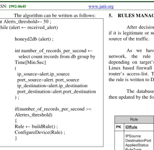
5. RULES MANAGEMENT
After decision is made about a connection if it is legitimate or not, a rule is built to block the source of the traffic.
As we have multiple devices in the network, the rule is dynamically formatted depending on target’s syntax: a rule for iptables Linux based firewall is not written the same as a router’s access-list. Thus, only information about the rule is written to DB and not the full syntax.
The database’s physical structure will be then updated by the following tables:
Figure 6. Rules Management - DB Structure
• Sensor: is the table defined previously • Rule: is the table containing the rule to
apply on a selected device (firewall, router, Linux server…etc.).
[image:4.612.89.520.282.708.2]ISSN: 1992-8645 www.jatit.org E-ISSN: 1817-3195
The structure is open enough to permit applying a rule on some devices and not to all of them. A rule about an external source may be implemented on border router or firewall, but there’s no need to apply it on an internal router for example.
6. TESTS AND RESULTS
Tests of the IPMS system were conducted in every step of the implementation. To test the IPS function we mass-insert data in the database using a script and changing every time the information about source IP and Port number.
For devices to configure, we started by Linux boxes configured with iptables as firewall. We will use the generic term “network device” to refer to these machines.
In this scenario, we used Remote SHell (RSH) to remotely configure network devices and permanently add filtering rules.
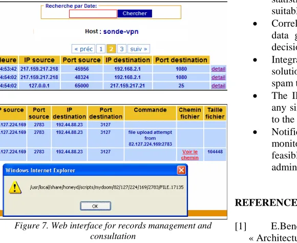
An example of collected data for a sensor is shown below. The link “detail” gives all the details about the record, mainly the payload and in case there’s any additional data (for example, for Mydoom worm, the attacker uploads a file, a Trojan; in this case, the path to the file is given too, as shown in the next figure).
Figure 7. Web interface for records management and consultation
From another hand, the rules generated are logged into the DB; the administrator can drop the
[image:5.612.84.374.461.698.2]rule or edit the rule if needed. We can also see if a rule is enabled or not (green or red light in the first column).
Figure 8. Filtering Management through the IPMS
As said before, these tests are made in a lab environment but at the same time are based on real results obtained before. It is also worth noting that these results are enough to have a clear idea of the efficiency of the whole solution.
A whitelist with IP addresses that should never be blocked was put in place to minimize the false-positive risk. Besides, a blacklist also is integrated to the system to be able to use external source of information about identified malicious source of traffic.
7. CONCLUSION
In this article we tried to summarize the work done to create an Intrusion Prevention Management System based on Honeyd, an open source high level honeypot.
The IPMS system is open to many enhancements and usages, such as:
• Decision module to be enhanced to a statistical or whatever other method suitable to the business it will be used in • Correlation between network events and
data gathered by the sensors can make decisions better
• Integrate the IPMS with antispam
solutions for example and use sensors as spam traps
• The IPMS architecture is open to handle any size of networks, from the most basic to the very large corporate networks
• Notification and integration with monitoring solutions like Nagios is feasible and can enhance in many ways admins’ response time to attacks.
REFERENCES
ISSN: 1992-8645 www.jatit.org E-ISSN: 1817-3195
[2] C. Doring. « Improving Networ Security with Honeypots », July, 2005. Thesis. [German Honeynet Project].
[3] L.Spitzner. « Honeypots: Tracking Hackers ». Addison Wesley, Septembre 2002. ISBN: 0-321-10895-7.
[4] E.Bendriss; B.Regragui. « Architecture Distribuée pour la Prévention d'Intrusion Basée sur Honeyd », NOTERE 2007 workshops, pg 137-142.