-DESCRIPTIon
OF
APPARATUS_ &l\.I TR-20 AHALOG
COH2UTEH-A.
Intr0QuctinnThe EAI TR-20 is
a
geneI~al purpose desktop analog cornputer.• t- . . • • .. ..
··l·t
l. ... S -capacl -cy ano.cccp,?oJ. J. -J.
It can perforlll the folloT-ring lineal') ~:.nd -non-lin08.1' mathe-D1aticai operations:
2 •.
3.
l.r.
,.
I'
o.
Inversion
(sign change)
C on·~J.nuous .• . -. -) .. n eg:-'a. -t - - '..l... i-:,~ on
The ·c;snsr:?tion of arbi tr·D.I';-( fU.Y.!.ctions
B. Lineal"- Compo11:ents
-I. Po~entiometers
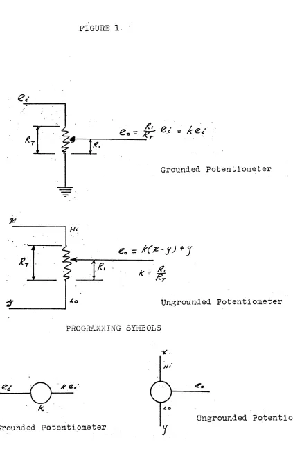
P0tentio:neters (pots) -are ac1ju-st,:).(Jle res{stors. There· .are t-:-;o type 3 fO"Lmci.. ontl1e TR-20 i.e. Gl?o1..~.nc.ed and ungrounded.
.. .
Grounded PQt.entioL!.c:te-rs. are U8'2:cL ~~i th _a peference voltage
to
obtain-a fixedvoltage
l~s~ the.n t:"lt8than
un.• - lJ,J ;.!. .. .,.. ~
Ungrounded pots are ge!leral1y used ~;i th nonline2.r compon~ntsJ
hOHeverJ -cher8 are some insts.nces -:rhen
they
al~e of use in linearoperation. Thoy H2.y boo gr6unde'd '::'~::1d i..lsed 8:3 a gro'unded pots, or
'~~hey may be used to add (l-K)E to B.n input or outlJu'c vhere K is a
potentiometer ietting
and E is a ref~r~nc~ voltage. Aschematic
of' grounded::.nd 'ung:c.'ounded pots
are
sho~.m in i'igure 1. (pc.ge 6)2.
The
1 ·· ",. , . .. , b . . ·.!-cunp I I J. e r l s;:;n~: . aSl C unJ. 1.1
of analos
computers. Am.-plificrs may be used to' 'per~fol~m. inver:3ion, slunnation,111ul tiplica':'" .be used Jeo pe:."fOI'l:l v2:I'i,ous' non-linec.r functions such as Dlul
ti:-:.li-. '
t · · ' r. ,. • , • •
ca lon, ~unc~lon.gencr~~lon, eGe.
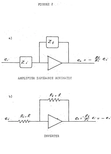
The inpu:G-output rel:3.ti::>nship of an operation2.1 9..raplifi.er is
solely dependent 'on 'she r2:.tios of' the feedbacH::: imp:;dE!.nce to the
input ·irn.pe6\.?~nce.
'Zr
= - -
z. ].
e.
].
- ZoP i 3 the: feed
back
i:mpeds~nce.L
Z; is the input imped~~ce
e. i·-::: the input
- J.
(~. . ....)
~·J.gure c-a
•
a. ~mplif~er as an inverter
':Phe ·e..:mplifier is .used 9~S an inverter :;hen both the inlJut
and. feedbe.ck imp 3 c19.21C 8 s are resistors of
.
ena ,The 81nplffiep i·s: 1,lsedas ·a·Yrlul tip·lisr Hhen the in~)ut and. the feedb':l.ck rosistol?S m-'e not equal.
if R
f . <·TIi . theri eo .< ei ..
'Tho TR-20 alloH.s
3
com.bination.s of g?';.ins ("t-Jit)"1out -:~he use, ' . , ,'~
of pots)". . For any, 2.r1plifi8~.· the u·ser may select ·oi
ther
lO~ ohm- , . . )
re~ist.ors,. 104 Oh_T11 .r~si stors, or a com.bination' of the t:'Jo •
Examples o:? these cases al"')(; sho"\-m in fieUl--C . (Page
3
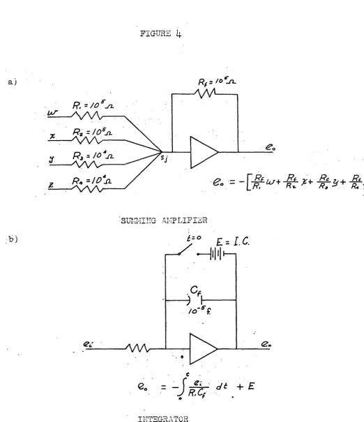
j c. P..mplii'ier as a summer.The artplifier m.sty bi;) useq. as a surnri!.er . . b~, inputting more
··:Chan 'one ·YO~ tage. Und:e'r tho usual ar!l8.ngenent the f'eedbaclr re-This ~iill alIa:·; the vol tc~ges
being,
figure L~-a.·
d. Amplif'fcn~ 8.S an integl"G.tor'
~Ih.en .the fecclb0.9l: l~esistor is rep19.ceci. "0:''- a cap'J.ci to-l",
-
~ • t .. .an J..nc:,:;g:~·'3.tor. ( T':1. .l:' J.gttre 4-0) ' . •
The
r'TR-20 has ·cap9.ci tor values of 10-;; :farads only aV"ail& .. ole for . integration.
C. - Fonlinear G.ollllJonent s 1. . Diodes
-The (:.lioGe;:; are ·een(n~8.1~y solid· stc,:te. wi th a fOl"'1·j8.rd re-sistance on the oJ:?c~cr of al?ou.!:.; 100 ohms. D3.sico.lly diodes are
analogous to tll.e Oper,9.tion or a check ve.lv8 in pipe flo'i. As
long
as
·::;11e plate voltage is gpe;1.terthan the C8.t~.lode volta.ge,· the diode conduct s. 7.1hen ~~he -plate vol tJge bec6m~s sirlaller" the
diode
representsinfinite
resista~c~.Cathode
Plato
.~.
IIDirection of' Cur1'6l1:t
- DIODE
S:L1~moL-2. l·J:ul tipliol')3
The quorter s'qual')e multiplier is b;3_sic_s.lty a function
gene-orator -:orhicD. doe-s .t..:"'o' V_L.l._'IJ _ J.. ~Oll()·.6..ng _ _ '--o. - . o"....oyt<:: .... inn !:'-.J ___ 1.1_ ... _ •
.. i:J
=
lEx+y)2 -
·(~-.;e21
'. ....,
'The T:1ct:ho'(l. of generating (.X
+
y)c:.. 'for quo.r"ter- 3QuB,1")emulti-~ . . .
. plic,;;itiol1 is si~nilar -co'~~11e I='.rinci-l-lle, useCl in all"che fixed c).tode
-,ro .L.. • ( , - 2 1 . .
.L 1.;tnc lI~on genera-cors "' su.c!1. as x., og x, ~~n x, etc. ) • The
func-f
.-: ( z.)' the input, f'Ol' the
Basically the
abl:';3 inputs" x -and y,end siv8san output A;j.
..
.?he Sine-Co sine Gener9.tor i:] 'siriila"p t;o t;h'e QSE in
-that
i t is basic9.~ly a i'uncti_on sen3rc~.tor. It provides 8~ f'ixed:runc-.t"iorr of ve.riables in
~ill
four que.dr:lnts (.=::i80
0 j for sine-cosino.(lircc-'t;l~~ on the corl-puter, hO~irOiJer ~ i·t requires the use of severe.l intt3g1' 8.tors and
4.
COl"1.p8r9..tor .T he e16ctrbni·c.ing device. -:..rnen ~~n. input roeB.ches a certain specified vol tF.J.ge a
origi.n8.1
inpu·c.
FIGURE
1.
Grounded Potentiometer
eo
'=
k()C -
J')
+
J
L·~'---
__
---~}fl
/(=~
i.o
Ungrounded Potentiometer
PROGRAIvE'IING SYI'IEOLS
_e:_~_' -~O
ke.'
Ic
Grounded Potentiometer
. ",;
FIGURE 2 ... :.
a)
"<2,'
- - - . - -.. -.f
Z. /
e'"(:t
-AMPLIFIER ·IHP~il.NCE SCH3i~ATIC
. b)
INVERTER
[image:8.617.108.547.89.697.2]'. FIGURE
J
eo=
-e,
IOS'...a...
e. ::
~-.: / 0e ,,'
.9
a " J1or
10
eo
= -
o./e:
"f
0./
a)
.w
[image:10.618.75.597.46.651.2]:1.
FIGURE
4
Sul':~HI1TG AEPLIFIZR
£=0
£= ..
I
C
"
..
INTEGRATOR
9
...-ill II
. -5 ('
10 T.
."
J
FIGURE'
5,
: PROGRAI1~lING SYNBQLS
. e·
ote
k
GROUNDED POT
INVE.RTER
~
tZo=-
!Gel.·dt
.
fI.e .
..
INTEGRATOR
till
~:fMULTIPLIER
~
j
eo
=
k(~-y)+J
I..
'UNGROUNDED POT
~
.,[>
y-'.-.'-o: . .
:>-_€_o_=_-r
7G+loy1
SUr1HING AI"IPLIEIER ' . .. ~ .
I.C.
SUi1rlING
INTEGRA.TORI
)
FIGURE
6
a)-SIn
we.
Sine
t,~Cosine.
tGENERATO£1
b) - J;- _'':'' (s/;',z)
---_
~,-
_'
t=.
0-5/.'1)&':"
. (- d'J!)
, - 51" 7C 7fl' ' _ co.s;r
_clJdt
Xc 05 or; (o'~)
X
~Sine x -
-·Cosinex
GENERATOR
HANUAL CON'rROLS· AND READOUT FACILI'TIES
A. tont~ol Panel
1. Overload" Alarm - The lamps are illuminated whenever theirassoci~ted amplifier i~ overloaded.
2. Power O:~-OFP. SYlitch - Contrpls application of
pri-, ,
mary a-c pO~Ter to
the
povTer suppl:y ofthe
computer.3.
Mode Control Switch ~ Co~trols the operational modeof the
computer. Positions areReset,
Ho~d~and
Operate.4.
VoltmeterFunction
Switch - ~orttrolvoltmeter
ppera-tion~- Positi~ns
are POT BUS, NULL, VH, AM?L, and BAL.
5.
NuLLFO? and 3.eference Selec tor
S~';i tah -Used
incon-j~nction with the voltmeter' to- me~sure ~oltgges by the null
co6patlson method.
6.
VMJack -
Provides for
extern~linputs to the
volt-me.te~ ~'Then_ the Vol t:neter Function S'wi teh is in the NULL or VI'!
7.
Ampli~ier Selector Switch - Selects an amplifier foroutput monitoring or balancing.
_ 8. AMPL OUT Jack"- Connected to the wiper of the AMPL
SEL sTt1itcn; facilitates connecting any amplifi,ec' output to external monitoring .or measuring equipment.
-:9.
':tE? OF 5Lii7E- PA~EL - Provides fixed- time scaling from-200 to 20 milliseconds. Must be on for iisplay on oscilloscope.
"TR-20 CONTROL PANEL
OVSRLOAD"
ALARI'1PO~'J'er
ON-OFF-MODE CONii:ROL
'--___ SHITCHNULL ""POT
Selec"tor
,s"fi tch :Vol trneter _ _ .,
VI:{ Jack
---
...
Voltmeter
~unction...
-.;...;..;sWitch
"R:2:P OP
Slave panel _ _ _ ...Voltmeter 3.ange
Selec tor
_______ ""
B~ Oscilloscope
1. Patch ~anel Display Unit· -.·Outputs frOY:l·ampli:rie~s are
patched into YJ.'·· Y2' Y
3'
andY'4.
There 3hould al~!ays be a jt'r;lper betueen xd ~ndA.. on this uni t (see fil~,·:; t pirl~c pago in t1EAI-TR-20 Computer - Operatol"ls Rbf'erence H 8ndboo:-{iI j .2. Channel·Suitch on.Scope
a..
L0.rge knob· - . Seleets ou-'cput desir·edi. e •.Yl' Yj, Y'), 01'" Y4;· 01~ i;f in II alln posi tion
. ' - . . ) .
Hill· give 6utpu'c.t~-'cm 711' Y2'
Y3
andY4
simul-.taneo\l.~:ly •
b. Small knob - Controls hori zontal loc·s.tion of'
display on scope.·
3.
F'unction 3-:·;i tcll. 0::1 Scoye(I j Of.f- ~ Remov·es- pO:·Jer. i'r'JDl scope.
J....
vl.Tr1-- ing urii t to horizontal in~ut •.
(.3)- X Plot - COrL."18C!~.S l)€:.:cch panGl display
terminal
C~
x-y
Plotter1. Pfl.tch PannI Di splay Uni·t - Output from. a:nplifier is
.
. .
.,Output fI'om gen:;:n~~?.te(1 ralTI.p i'1)nct~on ~s patcned into Xl- 'i'here should still be a ju .. --nper oet,'ce:rY Ad
8nd~ori
2. 'Plotter Control Pariel·
a.
Mode Select·Switch·
·(1)'' VAR - vvhen in this mode the SCALE FACTOR.
control
providesa means
of obtaining any. .
value of
scale
factor fromthe selected
. .
fixed· value dONn to zero
d-eflection.
(~) CAL· -·Permits.the operator to calibrate
the
plotter ~eflecti~n in rererehce to the
the ~yst~m~ This
allows
the setting ofX-Zero or Y-Zero.
(4)
FI~ED -.The s~~le factor applied to the,''lriput
signa~ 1~ controlled sol~ly bythe
, .
~'u\rGE s~'Il ten •
. b. ~CALE FACTOR CO~ltrol .. - Used. in ~·.onjunc tion ~";-i th
e1 ther
the
\TAR or C-ALi·Iode S~lec t :3;-/i tch to·,obtain scale factors
for
ou~put.c. a~NGE - Perzits the selection of eight indicated
scale factors.' , .
("Ell.I -
Computer
Hoduie t I'iodel12.8'J4.
1110 "'yaripldtter ,Sys'tem")
PROGRAHIYIIHG I·f.STHOD3
A.
IntroductionThe e:lsiest IJrOsranE!ing method is the 80-c.9.11c6 boot 3t~ap
The11e are ,;;ever8.1 steps in proC:'1anliling thi s met:lod uhich
.., "..;.
orci.or
, . ,
'of' Il.achi:r:.e un! t-s. .
Urite
4.
Sketch' a ci:rcui t diagJ~e.m.f l.-~ " • 1 t· t' ..
:::> ,\jne pll;rSlca quan ~ ~es anet
the scale f~ctor magrtitude.
~'lri
ce
the eir.cu1't; equations fro:.;'l "G!le.
,cir-.'
cui t eli agr8.lrl. The:::e equ8.tions' uil::" ;)e in
7.
'De'i-;ernine t.h~ required \/[<:lu08 for constanti,nput.
vcltage~ etc.8.
Sho~-; tll'8 values det.sr:nin0o.' in step7
next to the appropriate s:''Y·fool.s in the cirenit
B~
·P.rogramming
An-example of. this for programming only is the following
equation:
upon differentiation we have
dx
=
_kc;ktd,t
or . d-x
=
-kxdt
dx
-dt
=-kx
Obvlou~ly
the
comp~nerttwhich best represents the
relation-ship between the two variables'is the integrB:tor.
-~-~-~----[I>--'--~---Now if we insert a pot
which is the solution to dx/dt.
Now connecting the
out-·-put
andthe input
__
oI,z;_~_I!_'
--[V-() ...
"'---k-:K----.k
I
Returning to our _original equation
-kt
x
=ce
we
see that when
t=
o.
x
=
c .
. Therefore ,- . our ini tlal condl tlon is
Xo=
c
k
Another example of programming, again without magnitude.
. "
scaling, is the .solution of th.e Euler equatio"n for column
buck-ling (pin";'ended
l.·
2"·" ... '
~ - ~ - ' P 2 - E I .. - -. EI· Y.
dx
-~here
M
i~the moment
E .1s·· the
~.odulusof! electric1 ty
I is the momen tof Inert.ia
P 1s
t~~c9mpressive load on the column,·
y 1~
the deflection of the column ..
~p
,
,
.·~.1.:
.
.
;
.This may· be programmed using the "boot strap" method as
follows:
Integrate d
2
y
to get -
~
. d
Inte~rat~ ~d~
to get
+y_-_·C1'-_~k_V;_i-
----[D
+~
Put
+ythrough a.pot 'and an inverter
+'1
0
~
. ~
.J
-~ e~
~I
connect the various
co~ponentsand add initial
con-'di tions.
S"- f' Li'
- E1
oJFor the given problem the 's'lope
of-the colum 'will be zero
·in the center of the column.
With this in mind'
9a can be located
-. by "trial and error and the problemlrill be -.solved-.
c.
Magnitude scaling
Assuming that the following equation has been programmed as
shown; magnitude
.s~a.llngwould
b~1;nwith the choice of maximum
values.
dz
d't=x+y
Zo
Now assume ·that the following maximum values are selected:
·xmax
=
10
Ymax·
=
5
We will say, therefore,
that·· the computer variables are
~[X/lO]
;[Y/51 '
and[-Z/2]
.We will have also some "pot" settings ...[Rrz.fJ
t---[-%]
kL
Values of k-1-,· G1 ,.
~2·'G2
! ~and_k3may
b~found. .. by dividing
the-denominators of the. input by the denominators.of the output.
k 1G1
=
10/2=
5
_k
2
G2
=5/2 - ·2:5
Remembering that kl and k2 must·be less than 1· and that_ the
most _logical .cl:101ce- of. gain i"s -either·
1or
10 i tis obvious that
the ·following is the scaled program.
k
3
,'
is the ratio of, the . initial conditfon to themaxi-mum value·for·the output~
'D. Time scaling
,Occasionally it ·1s necessary, to increase or slow down the
. "
time :nec,essary for 'the
c6~puter
:to solve various problems. Thismay be d,one for, certain' fixed values dire,ctly on' the computer
for the rep-op and plotter, or'it may be accomplished by changing
',the inJ?u t ·to the program integra tors.
The direct method will be discussed in the section on
ad-. . . .
.,"Justi!l-g ·equi"pment. Time s.cali.ng is ·usually accomplished by
cor-'. recting the input to tl,le ,integrators., In the' previous example .
of the Eule~ E~u~tion problem it would be scaled in the following
manner.
- d
... )#:¥". I
t8
"
..
P
J"
-at,
.'
Notice that' the initial'condition to Integr~tor 1 was not
. time scaled. Only direct inputs to integrators are scaled by
EXAMPLE PROBLE!1S
The following problems are given as
e~~mplesof the
pre~viously discussed techniques.
1 •. A
body is projected vertically
up~vardat an initial
ve-'locityof 128.8 ft/sec.
Solve for the velocity 'and displacement
at·t sees.
Solut1.on:
If
air resistance is neglected,the
problem-- . . .
~~rlables
are the acceleration,.' velocity, and displacement.
Now maximum values of the .variables .mustbe selected.
The
maxlmumvalu~ ~f t~e acceler~tiondue
to gravity
i~of course,
. .
. . . 2
-32 ..
~ft/sec .
H~.w~yer;in
.o~er·not to ."crowd
Itour solution we
. . 2will ·let
~axbe
5~ft/sec . . 'For the same reason
't'Tecan set .'
Vm~x
as,
200ft/sec.
The maximum displacement
may be solved for:
~
v2: .' .
'4
x·10
4 '
.Ymax =. max ~ 2 '= 400
ft.
.
-.
~Am~x. 10.Preli~in~ry_
circuit diagram:
~. "
£Qo) (te~;
1
(
~oo]
.NOl-T Gains and. Pot settlngs· must· be solved .
. . . . ~ . .
Kl
=200
=
.25
but
a
~
32.2
ft/sec2 ,.
there'fore50 .
=.3~O,2
= .•644,
(ref)kl
=
(.,?5) (.,644)
=
~161
and k2 is found as
,200
.
k2 = 400 =
.5
_Fin~11yvo/200
~
/200
~ 12~bg ~~
sec=
.644
- . 0 ' . . sec
which gives
the
following diagram.1
.• I., I .
-
19
['J(o~]
[~J'
, Example 2.
The spring~mass-damping apparatus shot~n, below has the
follow-ing initial values:
k
=100, in
=2.5"
x
O,=4,
Xo
=0
It
isde-sirable
to
try several values of the'damping co-efficient, b, in'order' to 'study the effects of damping on this system. Consequently,
the follo~J'ing val~es will, be used for
b:
.50,
25, '12.5,6.25.
b
Solution: Note that the system has been displaced
"4;
units
from its equilibrium pOSition.
- The equation for the above system is a second order equation.
i.e.
This eq:ua.ti.on·'ls found by summing forces' in the x direction
-
F
1dx
, F 2 = bv=' b d t (a function of velocity)
F:3
=kx
(Hookcs lal·;r)Now solving the equation for the highest derivative:
" .. The preliminary cir~uit~ diagram wi;tl now be shown:
Jt.
" '
~
The problem variables are ac·celeration~ veloci ty, and
dis-,placement ; f t is necessary to. find the maximum values for these ..
'Let
,. . =·40 °max'v, ..
=
10'max
-x max ==
5-. , I
X 0 ' X
or
01Hf ,.
TO- '
oX5
Now the final circuit diagram can be drawn.
~
.-[ RtrfJ[;ipo
J
[~/:s"
J
,8#\
Wh
ere
k/m
8
=(2S}(8) -
100.·S
and 'b/m4'
= '16g'-=
~·5.
-..-?.5. .. _.
2S'
100 .. - -
.--- 1b.2-
125
:- 100 -:- ·_ 6.
25'
~- '.100. - • 0625 . .
an4 x
/S
=
4/5
=.8
.0
. rb
(? . 6._
t J '
\ f -\ .
\ ' 0 .
"
Note that as b approaches
0the system approaches an
Example-J.
A two degrees of freedom problemwl11 now be analyzed ..
1<,
-.~ . . .
Analysis of· the sy:;;tem g.1ves -the.- following equations:
(1)
m
1 xl=-
k2(X2~~1-)
- kl (Xl)·~bl
xl- (2) m
2
x
2
=_
F(t) --k2(x2-x1) -_ b2X
2or
The problem is programmed by first drawing the diagram for
equation (1), then the diagram-for equation
(2),and-then
connect-ing shared members.
-, The problem -is· scaled
byasstimingthat the two problems
-are separate.
By
scaling the bottom first an estimate of k2 x
2
1s found which may be used in the
first
equation .asthe
driving'force.
.
~, - ;l:.,
'0
.
):'L --;JC&O'
, 1<1/
.' . /f11,
~,
. ka
Example
4.
Beam deflection problem.
Solve the given beam for its shear, moment,
0slope and
deflection.
w:
/0#/i"
oIl III I/ol/ /7771 / / / / 1 /
J
~ 0 • i.::
i
0 0 " ~ISolution:
The problem variables are as folloVTs:,
dy/dx. = EIe
.y :;: .EI~
The preliminary circui t diagram TtTlll .be as follo~'ls;
-UI
. A,EIThe.problem will have to.be solved for ma::ci.rriu'values,.l.e.
Let
1"1 =
10 1 bs • /
in ·max
L =
3qO
inmax'
·Therefore
V
-
iDDO
Ihs.max'
l'l
=
100.000max
Ely
max.
The
value ofEI·· ':
ma.y ·be found by trial and error if. max .
it
1s
remembered
t~atbecause
ofsymmetry the slope angle is
o in the
center 6f the
begm~Computer variables
-[V/IOOO] ,
UliI
o
5] :
[
~]
·and. e
max •L
EIY
]
.
8
2xlO
"
..
The problem may nO~\f -be progra~ed.
[tCf]_
w~
[If
ITI
EXF:iESION OF COHPUTER AND LilB FACILITIES
I . ·Computer·
As of tb.is l·rri ting the computer nO"d h~s
·the
fo11oHihg corn-ponepts.,- 1-.1:'- 1'" It..
.. ' . J:iJ.fJ.p .1. J. ). C... S - 0
"Potentiometers .
a.
Carbo.n -
10Integl'lators - 6
!-T1?-l tipliers -' 2
Sin
-.Cos eener~tor-
1
..,...." .i.. • C . . .L.
~_ec t..ron2.c.· omparauor - 1
.-REP-OP -·1,
Thefoll.oHinS conpononts. are reconinended i'or :future e::pan-. sion ofijhe present ·TR-20·;
Potentiometers
-a. ~Iire-HoUnd -
.8
Integ-:I'8..tors -o...J _ • 2V.DFG' - 2
Relay COP1parator 1 ..
It is suggested that the integrators ,s.nd the V:CFG be the
next .u.nits pu.rchased • . T his should give a basic capability for
problems of, structual :n.3.ttu~e. It 'is' sug.se~t$d tho.t.
as
soon ase C onoIlli c :~l~ly po S s j .. b 1 e 0.(."> 1_ "1.' e -rTT'I'r1rt
.!. u 1 . . v lJ~ U'.
and
inte-grator uni ts that anothcp basic 'fR-20 be pux~chased. .An
alterna-tive to this sngSE!3tion Hould b,=-
the
purchase o~ e;::tra components;since the interch~.r~.g3Jf co;Y'.tl'J ).:-:..::)::.;3 on the TR-20 is a relatively
Thi0 should be tho' most economical rnet:lod of
fully utilizing ·o1.).r present TR.;.20 •. ·
1I.
Personnel
It
is suggested that a gr.aduate· assists.nt be'. placed in' chargeof th? 'COjJ1p~lter: labo!'ato!'J.'
H'e'
·.should 'be de'skedin o'rneEr
the:L-ab and' be respol).sible ?orthe ·ge~eral 'condi tion of the lab [tnd
, . ~'t-J~tchdog" of th.e. Gonp1..~.ter. .He·~h:ou~.d ·be cogni Z811,tof the
prin-ciples of :3,nalog computation' ',;-:tn,d p~ogr&!1rling.. Alnong his
duties.
sh<:>uld-be 'teacl.l.il!8 of' ii s:hort· courses" j preparation of
demon-- demon-- . . ' . . . ' .
·strations ~or the '8nd
upkeep of the machine itself.
. '
. Tlie labo.ratory should co ntain . the follo:';ing i terrls:
Benches or
tables f0r tlie
comput'er andacces30ries
. ,
Bench or table for prep~tching
stOl"age ~.rea
for'
patch boar'dB, bottleplugs,
Blackboard
[image:33.615.70.569.65.667.2]