RE'PORT PROGRAM GENERATOR II
RPGII
User's Guide
Version 3
June,
1975
Model Code No. 50021
D\TAPOINT ---..
.
~ION
The Leader in
Dispersed Data Processing
" ~'L> 11 ;;:;, Y .;; 1 t "I
liP!;:.! 1
user's l.J\..dae
Ji.lne, 14/5
lhis m~~ual is to be usee as e reference guioe tor the
p il(,Je
1. 1f;jr~Uuul.TJ.ul'~ 1 - 1
1.1 installing lne kP(" 11 Compiler 1-1
i.e:: He~uireo UtilHy Prograrns 1-1
1 • j VI A K 1'1 ll~ i.:i ! 1 .. c:
1.4 uefinlt10n of Terms l - c
l.~ ~eneral Uatapo;nt kP~ 11 ~rogrdm ~oyic i-~
1.b LJperaions' at Total T;me l-~
l.t' LJ~erdt;ons at i.Jeta; I rime 1-1!
1.tI General Program Cycle 1-4
1.'1 ~ource HIe Oruer and I-'rogram :;pecificdt;ons l-':>
e::. l.(J M 1\1 U r J I- 1 L L 1.1 SuN S U U H (; t:.
,.1 Columns l-e:: lPage)
i.~ l.olumns j-~ (L~ne) ~.~ ("ulumn 0 lForm lype)
~.4 l.olumn i (l,.omments)·
~.~ (.olumns
lS-bu
~Progr~m 1aentiticat~on)j~ CUNTHUL CAHU S~tClflCATIUN
5.1 (.olumns 1-~ (Pagel ana j-~ (Line) ~.~ Column b (Fo~m ly~e)
~.j Columns 7~4 .
~.4 Column 10 (UbJect Uutput) ~.~ Column 11 (List,ng Upt;o~S)
3.b
Columns 1~~14 (Core S,ze to ~xecute):$.7 (.olumn ld
3.b
Column ,~ lUebug)3.9 Columns lo~~5 '
~.lu Column ~6 lAlternate Col lating ~eQuence)
.s.ll L.oiurnns 2,.,;'74
3.1C: Columns 1~-tiO ~Progr?m laentif;cat10nJ
4. FILt ~~SLK1~11uN 5PlCIF1CAT1U~S
q~l Lolumns 1-~ (Page) and .s-~ LLine)
4.2 Column 6 (Form-Type)
4 •
.5 ~olurnns 7-14 (File ~ame) 4.4 l.Olumr'i 1:) lHie Type)4.~ lnput j-,le' 4.6 Uutput F i 1 es 4.7 Upaate Fi les 4.b L)isplaY fi leg
4.4
Lolum~ 10 ~File Uesign~t,on~4.,0
~r,mary ~flesi ;
c;;-! C::-l c: ... ~ c: .. ~
c::-c:: 2",,$
j-1 ..:)-1
3-1
j - l
3"1 ~-l ,$-c: .:>-2
,$-.s
.')-.5 S" .Sj - j
S-,$
4-1 4"1
L.'" 1
'. - 1
£ ... 1
4.11 Secondary Files
4.1~ Cha,nea Files
4.13 Record Adaress riles 4.14 Table or Array Files 4.15 D~mand Fi les'
4.1b Column 17 (t::nd of F;le)
4.17 Column 18 [Sequence) .
4.1b Column 19 (File Format)
4.19 F;>o;eCl f'ormat Files . .
4.~O VariabTe F~rmat Files
4.~1 Colu~ns 20-~3 (~lOCk Length)
4.22 DisK
ri
les4.2,) uther f, les
4.24 (.;01 umns '24-,0 (Recoro Length)
4.2~ Column 28 (MOd~ of Processing)
4.2b Consecut,ve Method
4.27 ~y AUDKOUT File
4.~6 Sequential ~y Key
4.~9 Sequential within L1mits
4.30 Ranoom M~thod
4.31 C61umns ~9-30 (Length af Key)
4.3~ Column 31 (Rec6ra Address ry~eJ 4.33 ~olumn 32 (File Urganization) .
Li.j4 Columns 33~34 (Uverflow' !noicator)
4.3~ Uverflow Indicator
4.>0 Columns 35-38 (Key Field Starting Location)
4.37 Column 39 (Extension Lode)
4.~b Column 40-40 (Device)
4.39 Use of tne LUAU£K Device for Program Chaining
4.4v SP~ClAL Dev;ce Support
4.41 Columns 47-52
4.42 Columns ~3-05 (Cont;nuation L1nes)
4.4.3 Column 53 4.44 Columns 54-59
4.45 Columns 54-59 (Name at Label exit)
4.~o COlumns oV-b2 (Extension)
4.47 Columns 63-b~ (Ur;veJ
~.4d Columns bO-o~ (Number of Sectors)
4.4~ COI~mn 00 IF'l~ Aauitionl
4.~U ~ol~mns b7~70 4.~1 ~olumn~ 71-72
4.~2 ~1-~8 l~xternal Inoicators)
4.5j Col~mM~ 13-74
4.~4 Columns 7~-bU (~rogram loentification)
~. tXIEN51UN j~lCIFICATIUNS
~.1 ~olumns 1-2 (page) ana 3-5 lLine)
'::>.c: Column b (Form fypeJ
6.
~.s Columns 7·10 ~-l
~.4 Columns ll-lb U':rom Filename) ':,."1
I;:).~ Lolumns 1~-2o (To F, lename) ';;-c:::
s.
t) t.; 0 I U ,01 n s r:. 7'" Yi:. (1 a 0 leo I" ~ I" ray 1'1 a me) '::1-")1;:). 1 I a ole i\J am e ~ - j
~ • (; A r I" a y I~ ;''Jr.1 e 'J - t~ ~.9 Lolumns"i5·jS (Number of ~ntr1es per kecoru) ';J.'::1
1;:).10 Columns 50-59 l~umber of tntries/laoleJ ~-~
~.ll Columns 4U-42 (Length of ~ntry) '::l-c
~.li:. Lolumn 4j lPac~eo or bi~ary ~ieio) ~-b j.15 Column 44 {u~c'mal Positions) '::l-j
j.14 Column 45 ( S e q u e n c e ) " ':;;-1
~.lS Columns 4b~~7 " ~-ti
1;:).16 Columns ~tl-14 lLomments) '::1-7
1;:).17 Columns 7S-bO (Program luentificationJ ~-H LINt:. C
uu
i~ 1 t. ~<b.l Columns b.G Column 0
b.3 Columns
b.L+ Columns b.S Columns O.b Columns
1,) • • / Columns
b.8 Lolumns b.9 Columns
:,) t-' I::. C IF 1 CAl 1 U III S
l"~ (Page) anc) (,;olumns j ... ~ (L i ne) lForm Type)
"1';'14 (I-; i enamel'
1:>-1"1 (Lines per Paye)
1~-14 (I- 0 rm Length)
2v-r::.2 lLine Number of Uvertlow Line) 23-24 tUverflow Li ne)
c!.':J-74
75-bO (Program Loent if i edt; on)
b-l 0-1 0-1 u-l 6-1 0-1
u-2
O-c b-i::: o-j~. INPuT SPtlll-ICA110NS j-1
"1.1 Columns 1-2 (Page) ana j-S ~Line) 7-1
7.~ Column 0 (Form lype) 7-1
7 • "5 Co I u m n s 7';'1 4 (I-; 1 en arne) 7-1
7.4 Columns l~-lb (Sequence) I-~
1.5 Column 17 (Num6erl 7~5
1.6 Column ld (Uption) 7-3
7.1 Columns 1Y';'20 (Record !dentitying ,naicator) 1-4
7.& H~cora lo~ntif~'ng Indicator /-4
7.Y Look Aheao Fields 7-~
7.1U Columns 21-~1 (Record laentification Coaes) 1-0
1.11 Not 1-7
7.1~ CILIU 7-1
7 • .i..::> Lharacter
7.14 ANU ~elat1onship
l.i5 Uk Relationship
7.10 Co'iumn 42
{.li Co'u~n 43 (Packed or binary r1ela
I.lb idM C6mpat{ole I-orffiat
1.19 uatapoini Compat;ole format
7.~U Columns 44-51 If,elo ~OCat'on)
...
j"-t) d-l
d-l
"i -"i
1-4
-,- J. (I
7.~1 Column 53 (l)ec;mal Position)
7.22 ~olumns 53~5b (Field Name)
7.23 F,eld Names - .
7.24 Fielo N~mes in UR RelationShip
7.25 Sp~ctal ~oro PAG~ .
7.2b Columns 59-00 (Control ~evel) 7.27 Ll-L9 lControl -Level Indicators)
7.2H Columns ~1-b2 lMatch;ng f;elds)
1.29 Matchin~ Field~ .
7.30 Col~mn~ 03-04 (Field Record ~elations) 7.~1 Record ldent;fy;ng Indicators (01-99)
7.32 Control ~evel (Ll-L9)ano
-1.33 ~xt~rnal Indic~tors CUi-Uti)
7.34 Halt Inoicator~ (Hl-89)
7.35 Columns 65-70 .
1.30 Halt lnuicators
j.37 Columns 11~74
7.3b Columns 75-60 (Program Identification)
b. CA~CULATluN ~PECIFIC~T1UNS
b.l L:olumns 1-1.2 (Pa<,)e) ana "'-5 -lLine)
b • 2 (.0 I u nl n b ( For m I y p e ) . . b.,j Columns
,';'.a
((.;ontrol Lellell&.4
Lolumns 9-17(lna;cators~8.5 Columnslb~27 ana C61umns 33-~2 lFactor 1 , 2) b.~ Literals
b.1 Columns 2e-32 (Uperation)
b.b Columns 43-4b (Resuit Fielo)
b.9 Columns 49-51 (~iel0 Length)
b.10 Column s~ (uec;mal Positions)
b.ll C.olumn 5..) (Half Adjust) .
b.12 Columns 54';'59 (Result;ng inoicators)
a.1S rest Results - .
8.14 Columns bO-74 (~omments)
b.15 Columns 7~-b0 (Program loent'f~cation) b.lo uperation Codes
8.17 Arithmetic Uperat;ons
b.ltj Add (AO())
8.19 iero an~ Aoa (Z-AuU) a.~O Subtract l~Uu)
~.~l Lero and ~ubtract (l-~Uu) 8 • C c! [VI U 1 t ;
p
J y Ul U L 1 )-H.~~ Oivtoe (Ulv) .
b.2~ MOlle Remdinder (MvH)
8.C:'i !:lquare "oot ~S~Ri)
0.t:'6 Crossfoot lXI-GOT)
~.21 MOlle upera£ions
8.28 I"'love (MUVI:,)
7-11 7-11 7-12 7-12 7-13 7-1~ 7-14 7-14 7-14 7-15 7-10 7-10 7-11 "i-17 '7-11 7-18 7-18 1-18
b-1 .
6.29 ~ove Left lMUV~L)
b.lO Move Lone Operations
b • .3 1 i"i 0 "e H; ~l h t 0 bi 9 h t. 0 n t: l fl.i H H '- U )
d.32 Move Hign to Low Lone lMHLLUJ
b •. B i-love L.ow to Low Lone (i~1LLLu)
e • ,)
4 ;v, 0 veL (J IN t 0 h; 9 h Lon e U·j l.. H L U )b.3~ ~o~pare and It:sting uperaticns
b.3b Compare (~UM~) d.3j lest-lone (ltS1Ll
c.3S ainary Fieio Uper~tion~
d • .39 ~et bit Un (bllON)
t;).~O ::let t.>1l Uff'lbllut-)
d.41 fe5t oit lltSlb)
d.4~ Setting lnoicators
b.4j tiet ~n lStIU~)
b.4~ ~et 0ff' (SlfUr)
b.4S urdnch;ng Uperations
0.4(:; Go 10 lL:.UTUl ".4/ rag t!Al,,)
b.4e Loo~up uperations
b~4~ LOOkup (LU~UP)
d.SO using t~e LO~UP
b.~! L.U~U~ with One lable
o.~2 L.UKUP with l'wo laDles
b.5~ keterencing the Table ltem ro~no
b.~4 LU~UP with an Array b.5~ ~~oro~tine Dperations
b.5b deg,n ~ubroutine lbt("Sk)
b.~j ~no SUDroutine (tNUSkJ d.5b txecute Subro~t;ne (~XSk)
b.59 Programmea Control 61 Inp~t anu uutput
b.b0 txception ltXLP1) b.61 Force (fURCc)
e.b~ vis~la~ (VSPLY) o.td keQo lKt::.AU)
H.b4 Cha;n-(LnAIN)
e.b:' Set Lo~er, Lirr.;ts Uperation ldc.1LLI
~.bb Auoio uutput Uperations
b.bf t';jee!-l (tH:.t.P) d.b8 Cl;('K'{CLl(';K)
b.b9 ~e~uy Gperatfons
8.70 Uebug lUtbUb)
b.ll ~pec;f,cat;ons
6.72 tXif ana ~LAb~ Uperat,ons
d."'.:> tl<ll l,Jperation
b.74 hLAbL ::lpecif;cat;on
6.75 Referencing Fielos
b.1b rieferenc,ng Tables ana Arrays
"
;b" :. 0
. 0-1 b
b-lb b~lb b-ll.f 6"'111 0-tl.1 (
.
O-C:..J b"'c) b-c::..s b-24 b-.:;:I;) b-C::" 0-2':> o-C::c b" c:C':> b-c:'t b-27 b-c:'.i b-cb b-c:b /j-i;:.11 0-211 0"i:9 0-211 d-j\,' d-~l: b - j ( je ..
;,l fI-.S 1b .. jc:'.
0-..$4 t:'--~b b-.$b 0-;'>0 b-!.J7 b-31 0-3>7 0"3;)7
d .. 3>c o-~b
(j-3d
.t;l ... ,!)1.f
b.7l . Referencing Inoicators
\
9. UUTPuf FURMAl SPtCIF1CA1ION
~.l Co~~mns 1-2 lPage) ana ~olumns 3-~ (Line) 9.2 Columl'" o (form Type)
9 . j Co 1 u m n s 7';'1 L.I l
r ;
len am e) 9.~ Column 15 lTy~e)9.~ Columns 1b-18 tAdo a kecord)
9.0 Column 10 lFetCh Uverflow)
9.7 Fetch-Uverflow
9.8 Columns 17-22 (Space/Skip)
4.4 Columns 17·1e lSp~ce) 9.10 Columns 19-22 (Skip)
9.11 Columns 2~·31 (Uutput Indicators) 9.12 AN~ ana OR L'n~s
9.13 External Inuicators
9.11.1 Control L..evel indicators
9.1~ Uverflow Indicators 9.10 First Page Ind~cator
9.17 Colun,ns S2-37 (Held Name)
9.18 PAGt .
'1.19 uate field
4.~O Column 36 ltoit Coces) 9.21 Column 39 (blank After)
9.22 Columns 4U;43 lend Position in Uutput kecord) 9.~3 Column ~4 lPac~ea or ~inary fiela)
9.c:.4' Col umns 4':;';'7(; (Constant or to; t Vlord)
9.2~ Constant - .
4.20 td; t V¥orc
9.21 ~d1t'ng Considerations
9.20 Columns 71·74
9.~9 Columns 75-80 (Progr~m Iaentification)
Appendix A. ~enerat;on and Use of ~~b l!
Appena1X b. Detailea RPG Object flow Append1x L. Heference TaDles
Appendix D. Compile Time Messages
Append,x t . UDJect I~me Messages
Appendix f. User Assemcly Language Facilities
AppenalX b. Input/Output Device Interfaces
Appenatx H. Coo1ng Sheet ~ummary
vi ;
9-1 9"1 9-1 9-1 9-1 9-2 9-2
4-e:
9-3 9-3 9-~ 9-4 9-5 9"0 9-b 9"'Q 9-7 9"b 9-8CHAPTER 1. I~TRODUCTION
RPG II is a le~9uaQe or;en~ed for busine,s data croee~sino.
Th;s docu~ent specifies RPG II for t~e Dataooint 2200. Source oroorams and data can be prepared usin~ RPGPREP, CRPGPREP, or
DATAFORM II.
After oreoar;no the source prporam, the RPG II como;ler,must be run to proQuce the oblect,prooram. The oblect orooram is a self-contained prooram which executes under DOS in the nor~al
manner.
RPG source proorams ar, r;gidly formatted. In the subseouent
text, ,ouree records will be referred to as i t they were eO·column Ho1lerith records.
1.1 Installino The RPG II Compiler
Comol,te instr~et;ons for inlt,11ation of the RPG II compiler are oiven in Appendix A, The appendix also contains detailed
instructions for compiling proorams and indexin~, indexed (Indexed Seouent;al Access Method) files.
1.2 ReQuired Utility Proarams
The following uttlitie, at ~he indicatedver,ion/~evision
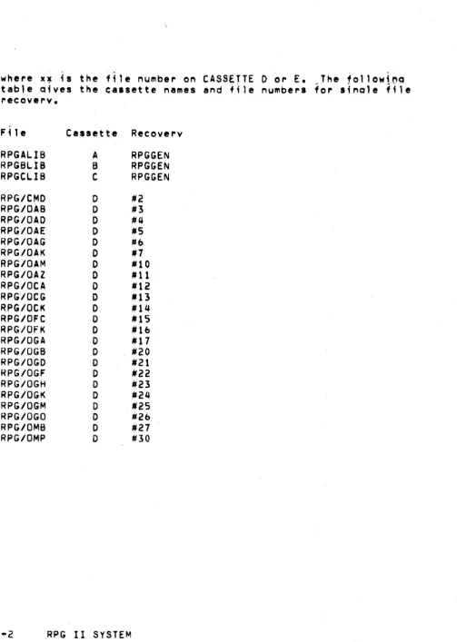
levels (or hioher) are reauired for full utilization of RPG II: RPGPREP 2.2 RPG Proaram Preparation Utility (DOS).
CRPGPREP 1.2 RPG Proaram Preparation Utility (Cassette). INDEX 2.1 DOS Index Utility.
REfORMAT 1.3 DOS Reformat Utility.
SORT 3.1 Disk Ooerat;na System Sort.
Note: Records sorted Ulina SORT ~.1 c.n~Qt exceed 249 characters in lenoth unless the
'1'
OPtion is specified to cre,te an AOOROUT file. The 'N' oPtion must be used for fixed format f;les when the'T' oct;on is om;tted. Unless soecif;ed otherwise, the outout wi"
be ;n ASCII seQuence.
1.3 WARNING'
R~~.II oenerates ,nd ~rocesses fi~ed disk iiles in a i~r~" ,hat differs_from the format used by RPG.II 1.1 and 1.~' .Al1 fi_ed format disk files.created by ~PG II Versjon 1 ~ust be conv~rted to tbe new format before processina as indexed, direct or outout
f; 1 es.
To convert to the new format:
1. Install the RPG II compiler.
2. Conver~ e~isting fixed disk files usinQ the DOS REFORMAT Utility.
" " , ' . ... J
The name of the source fil, should.be .ubstitu~ed for .. file-name-l. Ihe name of the converted out~ut file is substituted for
ti 1 .-name-2.
1.4 De~initi6n of Terms
. . .
EBCDIC (Extended Binary-Code-O,cimal Intercn,ne, Code)
Notati9nl Tn. 256-character maehine code u,ed inside the,
Oatapoint RPG II system.. Files are automati~~llY translated to EBCDIC when read, and from EBCDIC to ASCII (if necessary) when written.
Alohabetic Characters: The 26.alohabetfe EBCDIC charaeters and
the three EBCDIC characters ' . ' , '$', and '#'. Numeric
Charactersl The EBCDIC characters 0-9.
Special Characters:. The 217 EBCDIC characters not dei~ned as alohabetic or numeric.
Alohanumeric Characters: Any of the 256 EBCDIC characters.
. .
Alohanumeric Fields: All fieldS for which a d~cimal~posit~ons
soeci~ication ha,s not been made i~ th, approoriate c9lumn of the
soec;f;c~tions forms. Alohanumer;c fields can contain
alohabetic, numeric, or special characters •
... ~ ,~
Numeri~ F;~lds; All fields havine a decimal-positions
specifieation in the aooropriate columns of the specifications
forms.
Valid Oataooint RPG II Names: The folfowina rules aoelv to names used in RPG II oroarams:
RPG II f~lenamescan be from 1-8 characters 10naJ RPG II field names can be from 1-6 characters lana.
The first character of either a filename or a field name ~ust
be alphabetic (see ereced;na definitions of alphabetic
characters). The remainina characters can be any combination of alehabetic and numeric characters (seec;al characters are 'not allowed).
Blanks cannot apeear between characters in the name.
1.5 General Datapo;nt RPG II Proara~ Loaic
Everv Dataoo;nt HPG I I obiect oroaram has thp same aeneral
orOQra~ loaic. This loaic is based on the orocessina cycle
oerformed for each inout record read. Everv orOQram cycle involves three basic steos.
1. Readina information (;nput).
2. Performina calculations (processina).
3. Recordina results (outout).
In the RPG II cv~le, calculation and outout can occur at two different times in the cycle: total time and det~il time. 1.6 Ooeraions at Total Time
, .
Total calculation and output are normally oerformed on data accumulated for a Qroup of related records which form a c6ntrol arouo. When the fields of a record which determine the control arouo chanae, a control break occurs ;nd;cat;na a new control arouo is startino. When a break occurs (shown bv control level
;nd;cators beino turned on), calculation and output ooerat;ons are
oerformed usina information accumulated from all records in the previous control oroup.
1.7
ODerations at Detail Time_ .De~8il c~lculatioh~ ~nd detail putput.~re normally, Der~ormed
f 0 ~. i n d i v i d val data !'" ~ cor d s • Total 0 per a t i Q n S 8 rep e rf 0 r m ed,
before_de~a~l ooerat!ons. Thus 8 record W~ich_causes 8 co~~rol break is crocessed after the total operations for the previous
control oroup.
1.8 General Proaram Cvcle
An RPG obJeet "rooram proceeds throuah three major stees:
1 • I 1'1 it; 81 i z a t i on
2. ProcessinQ Cvcle
3. Termination
, "
In~ti.'tz8tion, co~.ists ofl 10adina,al1 nec!.sarv_~ables,
clearin9 all worktnQ area8, I~d ocenina al1.files_for ~h~
oroce.sina cvcle, The processina cvcle conststs of. writinQ 811
head~na and detail records, "eadina the neKt inout rec~rd and identijvina it. ceriorm~n9 t~tal ~"eratio~s ~~ 8 control break
occur., and then cal~ulatina all results,from the record .
previouslv read. This cvcle repeats until the last record ts processed.
The first ~nd last ~ycles are so~ewh8t d1ffer,nt from the nQr~al cvcle. Befor, the first record is read, deta~l outp~t co"~~tioned
bv the lP ind;cator and unconditioned detail out out is performed. Total, processina is bvpassed ul'ltil the cvcle afte,. the first
control bl"eak.
, ,
.
After.the last record has been read, the last record_indic~tor
(LR) is. turned on, as w!ll as all control levels, After totel
proc,ssi~a hal b,el'l performed, the norma' cvcle fs aborted and the termination routines are processed.
Termi~at;on conststs of: writina all necessarv tables and clos;na
all files.
. .
A detailed descrtption of the oblect proaram 10Qic is found in AcpendiK A.
1.9 Source File Order and Prooram Specifications
The source file consists of a source prooram, optionally followed by compi'e-time ~ables and arrays. The source file
contains UP to seven sections which can be coded on seven standard
RPG specification sheets and entered usino the RP~PRE~ uti lity proaram. The seven forms are:
1. Control ~ard Soecifi~ation. This soecification contains control information for the comoi1er.
2. File Descr;ption Soecification. Th;s specification conta;~~
file description information about all fi les used in the
prooram.
3. ;~tens;on Specification. This soecification contains extension
information about all tables and arraYs.
4. Li~e Counter Soecification. This specificat;on. contains
information about the number of lines to be printed on each form.
5. Input S~ecification. This specification contains information describino the recordsr~ad by the ~rooram.
b. talculation Specification. This specification describes all calculations performed by theprooram.
7. Qutput Format Specification. Th;s specification describes the format of all records written by the proaram.
The first part of the source prooram may end with: a normal EDIT end-of-file, a record containinQ '/*b' in co1u~ns 1-3, or a record containino '**b' in columns 1-3 (where,b indicates a
blank). The first two cases sianifv the end of the source .. orooram: the last ease s;onifies that a user library inclusion and/or comoile-time tables follow the source prooram.
If c90e from a user library ;s reouired, ($ee Apoendix F for details), a library inclusion record must immediately follow the
'**b' record. A user library is reouired .for SPECIAL jnput-output
devices and non-standard taoe labels. T~e EXIT operation (~ee
Chapter 8) also reouires a user library. The format of a library
;nclusio~ is: '*LIBRARY' in columns 1-8, followed by. one or m9~e
blanks, followed bv a DOS file name. If no e~tension ;s sUDPlied,
the extensio" 'RPG' is ~ssum!d. ,
If
eomoile·tim'tabl,~ are also used, a '~*b' record.sho~ld folJ9w the library incJy.i~n •.Comoile-time tables follow the first '!*b' r,cord if no libr.rv is
tnel~ded, ,or the second '**b' r,cord if one is u.,~. ~.ch
comoile-time table must aooear in the order soecified on the
extension !heets, .nd,mu,t be_seoarated bv '**b' records. See
Chapter 5 for a descr;otion of tables and .rravs.
-
. . ( , . ..After a~v of the orecedinQ ootional .sections have aop,a~,d, ~he
source ffle ,hQuld termi~.te with either a EDIT end-of-file or a record ~ontaininQ '/*b' in columns 1-3.
CHAPTER 2. COMMON FIELDS ON SUURCl
Th;S chapter defin~s entries common to all RPG coo1no sheets.
Each iodino sheet contains the followino entries: 1 • Columns 1-2 (PAGE).
2. Columns 3-5 CL I NE) •
.3. Column (:, (FORM TYPE).
4. Column 7 (COMME.NTS).
5. Columns 75-80 (PROGRAM IDE.NTIFICATIm~) • 2.1 Columns 1-2 (Paoe)
Entry Explanation
01-99 Paoe number.
Columns 1-2 are for number;no the soecificat;on sheets used in a lob. You can use more than one of each sheet, b~t atl sheets of the same type must be kept tooether. When all the specif;cations sheets are filled out, arranoe them in the followino order and number them in ascendina seauence:
1 • Control Card. 2. F; Ie Descriotion. 3. Extension.
4. Line Counter. 5. Input.
6. Calculation. 7. Output Format.
2.2 Columns 3-5 (Lfne)
Entry
~ny
numbers
. , .
Exclanat10n
Line numbers.
. '.
Columns 3~5 are ~,ed to ~umber the line.,on ~aeh sheet •. Column.
3-4
co~ta;~ creori~ted line numbers, so In m9st ea •• s linenumbe~ino is .'ready done. The~unnumb,r,d line, below t~e.
ereprinted numbers can be used for. additional lines or to insert a
line,~'twe,n tW9 ot~er eomplet,d lines. The contro) car~
sceetfieation lf~e is always Jine 01. Any other ltn~. on the sheets c,n be skioeed. The, line numQers used nee9 not be
eon,~eutive! but should be in a,cendino ord,r. ~'ne numbers are
optional •. Note: RPGPREP ~utomatieallY sueel;es, l;ne ~umbe~s. .
CQlumn 5
i,
always set to zero to allow later insertion of uo t~nine new lines.
2.3 Column b (Form Tyoe)
Entry Exel.nation
H Header
F File Deseriotion Soecifications.
E Exterision Soeeifieations.
L Line Counter Specifications.
. ... ,..
I Input So.eifie.tions.
C Calculation Soeeiiications.
0 Outout Format Soeeifieations.
Column b contains a code for each tvoe of source statement.
2.4 Column 7 (Comments)
Entry Exolanat10n
Comment line.
CHAPTER 3. CONTROL CARD SPECIFICATION
One. control card ;s required for every oroqram. It orovides information about your proqram and Your system to the RPG II
compiler. Without this information your source proqram cannot be translated into an RPG II object orooram.
3.1 Columns 1-2 (Paoe) and 3-~ (Line) Refer to Ckaoter 2.
3.2 Column b (Form Tvpe)
An H must aooear in column b. A control card with an H in column b must be entered for every oroor~m even if all other
columns are left blank. 3.3 Columns 7-9
Columns 7-9 are not used. The prOQram ;s comoiled in the available core storaqe.
3.4 Column 10 (Object Output)
Column 10 is checked and if it contains neit~~r C, D,.or
bl~nk, a ~arnino is produced, The PrOoram identification. is
;onored. No oblectprooram is oroduced when severe (terminal) errors are oresent ;n the source statements.
Entrv Blank
B
1. The Object orooram ;s oroduced (if no severe errors are fo~nd).
2. The orooram l;stino ;s printed.
1. The oblect orooram ;s prOduced (if no severe
errors are fo~nd).
2. The proqram listino is not printed.
Column 11 provides for listino options at the t·ime your source orooram is compiled. If any severe errors are found dur;no compilation, the system halts after completino the
listina (orovided a listina is to be orinted).
The blank entry ~s th!. usual case, oroducin~ en object orooram
(ii
no severe,errors are.found~ and a source ~roaram listina. The
orOQram listina consists of the,source orQQ~am, error mes.aae" and a core ~a~, The core mao lists such information as re'at,ve addresses of fields, eonstan,s, and
I/Q
areas~ The core mao is orinted only. if the or09ra~ is succ,ssfully comoiled •. The B entry~eans th,t no oroaram l;stina is orintedl however, an object
DrOQram is oroduced.
3.&
Cotumns 12-14 (Core Size to Execute)Core Size, to ~xecute is documentary only and does not affect oroaram execution in any way!
Entrv
Slank
01-13
Exolanation
The core s~oraae reauired for object oroQr,m
execution is the same al that used to comot'e the oroaram.
The,core s~oraae reouiredior oroqram ~~ec~ti~n
(ii
different from ;ore storaoe available for object oroaram aeneration).
Use columns, 13-14 to soecify s~me mult~ole of
lK
bytes of storaae (K=1024)~ Columns 13-14 document the core storaae required for oroaram execution. The entry must end in column 14.
3.7 Column 12
Entry
Blank,
o
Q
H
T
Exolanation
No additional 250-byte increments are needed.
One additional 25c-byte increment is needed.
Two additional 250-byte increments are needed (512
b~tes).
Three additional 25c-byte increments are needed (7&8
bytes).
Column 12 may be used to soecify additional 25b~bvte
increments of storace. These increments document an extra l/UKf
1/2K or ~/4K of storace to be recuired in addition to the storaae
specified in columns 13-14.
3.8 Column 15 (Oebuc) Entry
8lank DEBUG operation ;s not performed.
1 DEBUG ooeration ;s per.formed.· In order to oerform a DEBUG ooeration:
1. A 1 must aopear in column 15 when the source orocram ;s como;leo.
2. The DEBU~ ooeration code must aopear in calculation
specifications.
3.9 Columns 16-25
Columns 16-25 are not used. Leave them blank.
3.10 Column 26 (Alternate Collatina Secuence) Entry Explanat;~n
Blank Normal (EBCDIC) collatina secuence is used.
A ASCII collat;na seauence is used.
Use column 26 if lob ;ollatina secuence is in ASCII. Secuence check;nc, comoarisons and indexed disk files will be
processed in ASCII secuence. 3.11 Columns 27-74
Columns 27-74 are not used. Leaye them blank.
3.12 Columns 75-80 (Proaram Identification) See Chaoter 2.
CONTROL CARD SPECIFICATION
PIroGRAM _ _ _ _ -::--::=-=::-:-:c-_PAOGAAMMEA _ _ _ _ _ _ _ _ _ _ DATE _ _ _ _ _ POGE_Of'_PAGES ,~ ... TYPE At.. lERNATE COLLATING SEQUENCE fAJ
PO UNE
NO, NO.
FiQure 3-1. Examole of Control Card Soecificaiion.
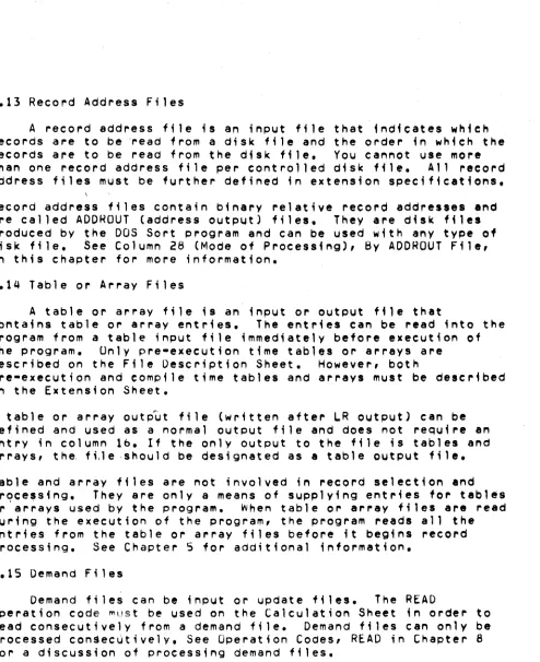
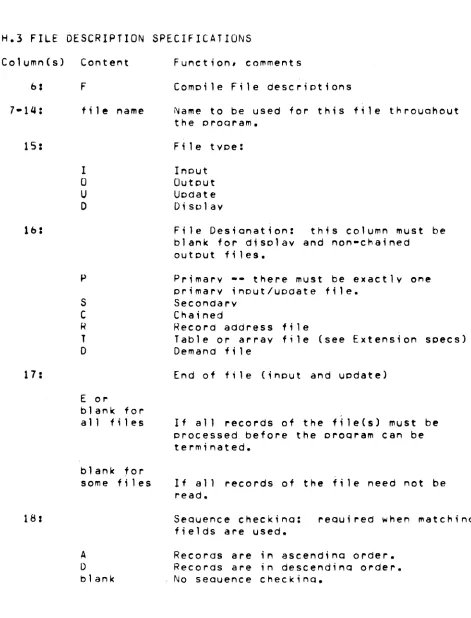
CHAPTER 4. FILe DESCRIPTION SPECIFICATIONS
file descriPtion specifications are required for every file used by a program. write these specifications on the File
Descr;pt;on Sheet. Only one line is needed to describe a file. 4.1 Columns 1-2 (Page) and 3-5 (Line)
Refer to Chapter 2.
4.2 Column b (Form Type)
An F must appear in column 6.
~.~ Columns 7-14 (File Name)
Use columns 7-14 to assign a unique filename to every file
used ;n your program except compile-time table and array files, which must not be named on the File Description Sheet. (Compile time tables and arrays are described on the Extension Sheet). The fi lename can be from 1-8 characters long, must begin ;n column 7,
and must be a valid RPG 11 name. The filename can be th~ same as 'a field name.
Pre-execution time table ana array files are described on the File Descr;pt;on Sheet.
When assigning file names for processing existing indexed files, the file name should refer to the index to be used. The assoe;ated data file wi1 1 be selected whenever the index ;s referenced.
4.4 Column 1S (F; Ie Type) Entry Explanation
I Input f ;,1 e U Output f ;1 e U Update til e D Display 1; 1 e
Use column lS to ident; fy the way in which your program uses the
file. All input file descriptions must preceed other file descriptions.
~.S Input File
Input files are records that a program uses ,s a souree of
data •. When input files are described in , program it indicates that records are to be read from the f;le. All input files except table and array files must be further described on the Input
Sheet. Table and array files must be further described in the Extension Sheet.
4.0 Output Files
Output files are records that are written or printed by a program. All output files, except table and array output files, must be further described on the Output-Format Sheet.
4.7 Update Files
Update files are disk files from which a program reads, record, updates fields in the record, and writes the record back
in the location from which it was read. Update files must be
further described on both the Input Sheet and Output-Format Sheet.
A chained file or a demand file may be upd,ted at detail time, at total time or exception time. All other disk files can be updated only at detail time during the same program eycle that reads the
record.
4.8 Display Files
A
display file ;s a collection of information from fields used by a program. The OSPLY operation code must be used on the Calculation Sheet in order to display a field or record direetlyfrom storage and/or key data into a field or record in storage. Display files need only be described on the File Description Sheet. The device associated with a display file must be a
keyboard-display (CONSOLE). See Operation Codes, DSPLY i~ Cha~ter
8 for more ;nformat;on.
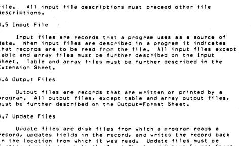
4,Q Column 10 (File Designation) Entry
p
S
Pr;mary file
Secondary file
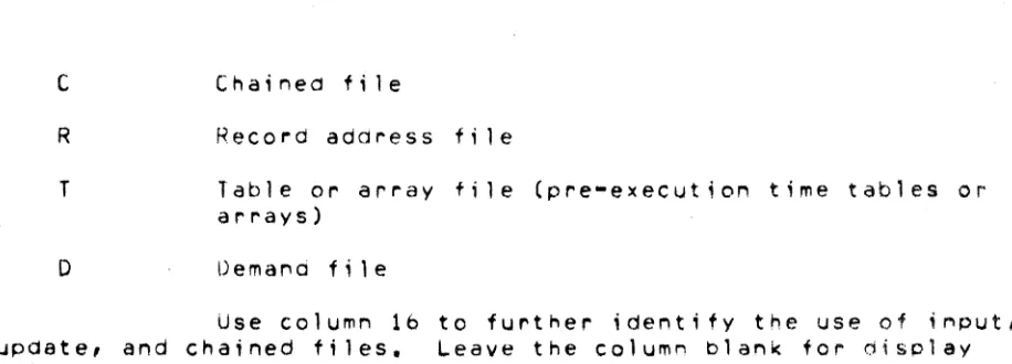
[image:24.612.51.546.95.382.2]C
R T
D
Record address fi Ie
Table or array file (pre-execution time tables or arrays)
Demal"d file
Use column 16 to further identify the use of input, update, and chained files. Leave the column blank for display files and all output files except Chained and table output files.
A primary file ;5 the main file from which a program reads records. In multifile processing the primary file is used to control the order in which records are selected for processing.
It can be an input or update file. In programs that read records from Only one file, that file is the primary file. Every program must have one and only one primary file. The primary file
descriPtion must be the first file ~escr;pt;onentry.
,
4.11 Secondary Files
Secondary files apply to programs that do multifile
processing. All of the fl1es involved i.n multifile processing, except the primary file, are secondary files. A secondary file can be an input, or update file. Sec~ndary files are processed in
the order in which they are written in the file descriPtion specifications, except when matching records (MR) or when the
FORCE operation ;s used. Note that table, chained, and demand
files are not involved in record selection. in multifile processing.
4.12 Chained Files
A chained tile is a disk file that ;s read or written
randomly via the CHAIN operation code. A c~a;ned file can be an input, o\Jtput, or update file. If H is output and indexed, ttole A option must be specified in column b6. This is because a chained,
indexed file must haVe an index built using the INDEX Utility Program. If this has been done, the file already exists and any records written are appended to the existing file.
[image:25.612.100.558.77.242.2]~.13 Record Address Files
A record address f;le is an input ffle that indicates which records are to be 'read from a disk file and the order in which the records are to be read from the disk file. You cannot use more
th~n one record address file per controlled disk file. All record
~ddress files must be further defined in extension specifications.
Record address fi,es contain binary relative record addres.e. and are called AODHOUT (address output) files. They are disk files produced by the DOS Sort program and can be used with any type of disk file. See Column 28 (Mode of Processing), By ADDRQUT File,
;n this chapter for more information.
4.14 Table or Array Files
A table or array file
;8
an input or output file thatcontains table or array entries. The entries can be read into the program from a table input f;le immediately before execution of
the program. Unly pre-execution timetables or arrays are
described on the File Description Sheet. However, both
pre-execution and compile time tables and arrays must be described in the Extension Sheet.
A table or array output file (wr;tten after ~R outPut) cen be defined and used as a normal output file and does not require an entry in column lb. If the only output to the file is tables and arrays, the, ftle ,should be designated as a table output fi Ie. Table and array files are not involved in record selection and prqce,sing, They are only a means of supplying ent~;es fo~ tables or a~rays used by the program, When table or array files are read during the execution of the program, the program readS all the entries from the table or array files before it begins record
processing. See Chapter 5 for additional information.
4.15 Demand Files
Demand files can be input or update files. The READ
operation code ~ust be used on the Calculation Sheet in order to read consecutively from a demand file. Demand files can only be processed con$ec~tively. See Operation Codes, READ in Chapter 8 for a discussion of processing demand files.
[image:26.612.54.548.40.646.2]4.16 Column 17 (End of File) tntry
E
~lan~
All records from the fi Ie must be processed before
the program can end.
1. The program can end whether or not all of the records from the file have been processed.
2. If column 17 is blank for all of the files, all records from every file must be processed before the program can end.
Column 17 applies to programs that perform multifile processing. Use it to indicate w~ether or not the program can end before all of the records from the file are processed. It applies only to input and update files that are
used as primary or secondary files.
If the recordS from all the files must be processed, column 17 must be blank for all files, or contain E's for 811 files.
A program that performs multifile processing could reach the end of one fjle before reaching the end of the others. It th~refore needs some indication of whether it is to continue reading records from the other files or end the program. An entry in column 17 in the descriPtions of the files provides that indication.
4.17 Column 15 (Sequence) Entry
A
o
~lank
Sequence checking is to be done. Records in the file are in ascendin9 order.
Sequence cheCking ;s to be aone. Records in the file are in descending order.
No sequence checking ;s to be done.
Lolumn 18 applies to update files, and all input files except table, array, chained, and aemand files. Leave column 18 blank for outputl display, table or array files, and chained files. Use;t to indicate whether or not t~e program ;s
to check t~e sequence of the records. Use columns bl-b2 on the Input Sheet to identify the matching fields containing the
sequence information. The proper collating sequenee for sequence checking (EBCDIC or ASCII) is determined by the column 26 in the Control Card Specification.
Sequence checking is required when matching fields are used in the records from the file. When a record from a matching input file is out of sequence, the program halts, and the operator has three optionSI
1. Bypass the record out of sequence and read the next record from the same file.
2. Bypass the record out of sequence, turn on the LR indicator and perform all end-of-Job and final total procedures,
3. Cancel the entire program.
See Appendix A for a detailed descriPtion of operating procedures.
4.18 Column 19 (File Format)
Entry Explanation
Fixed-length records.
v
Variable-length records.In Datapoint RPG II there are two types of file organizations, fixed and variable. Disk files may be either' cassette files must be variable, files on other d.vices must be fixed.
4.19 Fixed Format Files
These files have definite record length and are not subject to special processing, Disk files to be updated or processed
randomly must be fixed format. Se. Appendix G for further details about fixed-format disk f,les.
4.20 Variable Format Files
These files nave a maximum record lengtn and are compatible with Datapoint software using the seQuential record format sucn as
the general purpose editor program EDIT. On input, blanks are expanded; on output, blanks are compressed. See Appendix G for
furtner details about variable-format disk files.
4.21 Colum~s 20-23 (Block Le~gth)
entry Expla~ation
Number Length of block.
Blank Default bloek length.
These columns have differing interpretations depending on the device assig~ed for the file (see Columns 40-4b). 1+ an entry ;s specified, it must end in column 23. Leaoi~g zeros may be
omitted.
4.22 Disk Files
The blOCK length for fixed-format disk files may be a multiple of the record length. Th;s is allowed for language
compatibility, however, Datapoint RPG will always assign the most efficient block length. For variable-format disk f; les these columns must either be blank or equal to the record length.
Tape Files
These columns may either be blank or contain a multiple of the record length.
4.23 Uther Files
These columns must either be blank or contain the record
le~gth.
4.24 Colum~s 24-27 (Record Length)
~ntry
Number The number of characters used in each record (limited by the device used).
Use columns 24-27 to indicate the length of the records ;n the file. For variable-format files the record length defines the maximum size ofa record. The actual size is
dete~mined by the data read or written. ~or fixed-format files,
information ;s transferred in units of the record length. All of the records in one file must be the same length. (For update
filesl the length of a record after it i8 updated must be the same as before it was updated). The maximum reco~d length allowed and the size of the 1/0 area assigned depend upon the device aSligned to the file. The record length specified, may be shorter than the maximum length for the device. The entry placed in these columns must end in column 27. Leading zeros can be omitted.
4.25 Column 28 (Mode of Processing)
Entry
L.
R
Blank
Explanation
Sequential within limits.
1 • Random by relative record
2. Random by key.
3. By ADDROUT file.
4. Direct f11e load (random
1 • Sequential by key.
2. Consecutive.
number.
load).
Use column 28 to indicate the method by which records ar. to be procelsed. Only indexed disk files can be processed sequentially by key or within limits. Disk files that are indexed, chained or controlled bV an ADDROUT file can be
processed randomly. All other files must be processed
consecutively.
Colum~ 31 is used to further identify the processing method. See
column 31 (Record Addre.s Type) in this chapter.
4.2& Consecutive Method
The consecutive method applies to all files. During
consecutive processing records are read in the order in which they phY8ical'y appear in the file, The contents of spaces left for milsing records in direct (fixed-format) files are read as though the records were there. (Such spaces are filled with blanks).
The program reads records from tne file until either tne end of that file
;5
reached or the program ends due to tne end-of-f;le condition of another file. See column 17, End of File, i" tnfsenapter for more information about the seco~d co"dition.
4.27 By ADDROUT Fi 1e
An ADDRUUT (address output) f~le is a record address file produced by the DOS Sort Program. I t ; s a fi Ie of 3-byte disk
records containing binary relative record addresses of records in
a disk file. RPG II locates and reads the record at the spec,fied address in the original disk file. RecordS are read in this
manner unt; I eHher the end of the ADDRUUT fi Ie ;s reacheo or the program ends due to the end-of-file condition of another 'ile. See Column 17, t:.nd of File in this chapter for more ;nfOl"i,lat;on about the second condition.
4.28 Sequential by Key
Processing sequentially by key applies only to indexed disk files that are used as primarY, secondary or demand files.
Records are read in ascending key sequence established when the file ~as INDEXed by the INDEX utility program (See Appendix A),
The alternate collating sequence option (Column 26 in Control Card) must agree with the option used when INDeXing the fi Ie
(EBCDIC or ASCII). The program reads records from the file until .ither the end of that file ;s reached or the program ends due to the end-of-tile condition of another file. See column 17, End of File, in this chapter for more information about the second
cond;t;on.
4.29 Sequential ~;thin Limits
Sequential within 1 ;mits processing is accomplished using the SETLl operation code during calculations. The SETll operation code ;s used to establ;s~ a lower limit for sequentially processing primary, secondary, or demand files. The upper limit (if not end-of-file) must be checked using the CaMP operat;on code.
When using SETLl with primary and secondary files, care should be exercised to discard the first record read (as part of the norma'
input cycle) prior to entering calculations and executing the f;rst SETLL. (See Operation Codes, SETLL in Chapter B).
~.30 Random Method
Two methods, random by relative record number and random by key, apply to chained files only. They require the use of the CHAIN operation code. The records of a file to be read or written must be processed by the CHAIN operation code. The records are read or written onlY when the CHAIN statement~ that identify them are executed.
When processing fixed blocked disk files "directly" (without using an ISAM index), relative record numbers are used to identify the records. Relative record numbers identify the positions of the records relative to the beginning of the file. For example, the relative record numbers of the first, fifth, and seventh records in a file are 1, 5, and 7 respectively. (See Operation Codes, CHAIN in Chapter 8).
For indexed files, record keys must be used to locate the records. A record key is the information used to match ynique dat~ in a field in each record that ;s used to identify that record. Record key fields are defined when a fixed blocked disk file is indexed with the INDEX utility program (See Appendix A)~
Records are read during the calculation phase of the program. Therefore, fields from these records can be uaed during detail or total calculations. Note then, that fields of records read from chained update files can be read and altered during calculations and the records can be updated (written back on the file with alterations) during output.
4.31 Columns 29-30 (Length of Key) Entry
Number Length of record key or AODRQUT file record
Columns 29-30 apply only to inde_ed disk files and
record address f,les. Enter:
1. The length of the record keys ;n indexed files.
2. Tne length of the records in ADDROUT files.
All of the key fields in the records in an indexed file must be the same length. The maximum is qq bytes. All of the records in an
AOOROUT file have a length of three. A leading zero is never required.
4.32 Column 31 (Record Address Type) Entry
A
I
Blank
Explanation
Record keys ;n unpacked format are used ;n processing indexed tiles.
The file is being processed by means of an ADDROUl file or the file ;s an ADORUUT file.
1. Relative record numbers are used in processing sequential and direct files.
2. A sequential or direct file is being loaded. 3. RecordS are read consecutively.
Column 31 indicates the way in which recordS in a disk file are identUied.
Column 32 (File Organization or Additional 1/0 Areal 4.33 Column 32 (File Organization)
Entry Explanation
1 Indexed file.
T ADDROLJT file.
Blal'lk Sequential file or direct file.
Use column 32 to identify ;l'Idexed and AOOROUT files. See Column 28, Mode of Processing for further details.
4.34 Columns 33-34 (Overflow Indicator) Entry
OA-OG,
OV
Explal'lation
An overflow indicator is used to condition
records in the file. The indicator specified ;s the Ol"1e used.
Blank No overflow indicator is used.
Columns 33-3q apply to the output file assigned to the printer. Use these columns to indicate that you are using an overflow indicator to condition records being printed in the file. Any overflow indicators used 4n a program must be unique for the output file assigned to the printer. Note that only one overflow indicator can be assigned to a ffle. Do not assign overflow indicators to a console file.
4.35 Overflow Indicator
Overflow indicators are used only with printer files, primarily to condition the printing of heading lines. If you intend to use an overflow indicator to condition output lines on the printer, yOU must 88s;gn an overflow indicator to the printer file on the File Description Sheet (columns 33-3Q). The same indicator must be used to condition all lines that are to be written only when overflow occurs.
If the destination of a space/skip or print operetion is a line beyond the overflow 14ne, the overflow indicator
is
turned on andremains on until all overflow lines are printed, However, if a ak1por space is specified that advances the form palt the
overflow line to the first line or past the first line on a new page, the overflow indicator does not turn on.
If an overflow indicator is used as a conditioning indicator, it indicates that output is to be performed at overflow time. This applies whether or not the line conditioned by the indicator is in an AND or OR relationship with other indicators.
The o~erflow 1nd'cator may be set by the SETON or
SETOF
operetion code. After all total records nave been written, however, the indicator ;s set as it normally is in accord witn tne overflow line.4.3& Columns 35-38 (Key F;eld Starting Location)
Entry Explanation
1-255 Record pOSition in which the key field begins.
Columns 35-38 apply to indexed files only. An entry must be made in these columns for an indexed disk file. Enter the
location in which the key field begins ;n indexed file records.
The nu~be~ entered must end ;n column 38. Leading zeros can be omitted.
4.37 Cqlumn 39 (Extens;on Code)
E
L Line counter specifications further describe the file.
Column 39 applies to (l)table and array f;les that are to be read during program execution, (2)record address files, and (llthe output file assigned to the printer. Output fi les that are assigned to the printer can be described on the Line Counter Sheet, Tables, array, and record address files must be described on the txtens;on Sheet.
4.38 Column 40-46 (Device) tntry
P~lNTt~
CUNSOLE
DISK
READER
TAPE
CASSEll CASSET2
LOADER
SPECIAL
Keyboard Display. Disk.
Card Reader.
Industry·compatible 9 track tape unit. Rear tape cassette.
Front tape cassette.
Pseudo-device for use with the DOS CHAIN command Special input/output device not supported by RPG II.
(See Appendix F).
These columns are used to specify the input/output device to be used for the file. All entries begin in column 40.
The devices that can be used depend upon the record form.
AVAILABLE DEVICES
••••••••••••••••••••••••••••••••••••••••••••••••••••••••••••
FILE FORM DEVICES MAXIMUM
BL.OCK L.ENGTH
.-
...
---
...
-.-~-...
~...
-
....•.•.•...
...
Primary or Disk DISK (fhed or 9999
Secondary variable format)
Input
Cards READER 80
Tape TAPE 1024
Cassette CASSETl orCASSET2 249
Keyed In CONSOL.E 78
...
_-
...•...
_-
... .
Chained Input
F i1 es Disk DISK (fixed format)
9999
...
_-
...
---
...•...•....•....•
Update Files (Primary, Secondary, or Chained)
Disk DISK (fixed format) 9999
...
-.--.-
....
--
....
--
...
-~...•...
...
Output Files Disk DISK, (fixed or 9999
variable format)
·Tape TAPE 1024
Cassette CASSETl or CASSET2 249
Printed PRINTER 132
CRT CONSOL.E 60
..•...
-
...•.
---•...•...•....•.•
D;splay File CRT CONSOLE 80
--
...
--
...
-
....•...
DOS Chaining Pseudo-device LOADER 80
--
...
--
...
--
...
---...•.
Special Files ? SPECIAL q999
--
..
-
....
-.-
...
-
...
-~.-.-...
---.-
...
-
...
-
...
-
..
-
.
... .
4.39 Use of the LUADER Device for Program Chaining
This device may be used to construct a command line to be executed by the DUS command processor after the normal end of an RPG II object program. TMe LOADER must be used as an output file, and the command line can typically be written during the last total cycle (LR-time). The simplest use of the LOADER ;s to invoke some other program, for example, the DOS SORT. By
constructing a sequence of DOS commands on some disk file and then writing "CHAIN file" on the LOAD~R, where "file" ;s the DOS name of the command file, more complex sequences may be realized.
Only one record may be written on the LOADER during the execution of the object program. If the object program aborts, rather than concluding normally, the command line is ignored.
4.40 SPECIAL Dev;ce Support
You can process files using devices not supported by RPG II. To do this, you must indicate that the file will be handled by a SPECIAL device (SPECIAL in columns 40-46 of the File Descr;ption Sheet). You must also supply a subroutine to perform the 1/0
operations required to transfer data between the SPECIAL device and core storage (subroutine name in columns 54-59 of the File DescriPtion Sheet).
The following can be used with SPECIAL files: FORCE operation cod ••
READ operation code.
The following cannot be used with SPECIAL files: CHAIN operation code.
Spacing and skipping.
S~ECIAL files can only be processed consecutively. See Append;x F
for the conventions used by HPG II to call the input-output subroutine.
4.41 Columns 47-52
These columns are not used and should be left blank. 4.42 Columns 53-&5 (Continuation ~ines)
4.43 Column 53
Entry
A
o
S
N
U
K
Explanation
Assign disk file name at run-time.
Disk file name defined at run-time.
Standard labels are used.
Non-standard labels are uled.
No labels are used.
Continuation Record.
If tl'le file being defined;s a disk f1.1e, co1.umn 53 may contain 'AP or
'0'.
(If it fs left blank, 'A' is assumed.) When the'A'
.entry is used, the obJect program will ask for the DOS externa1 file name to assign to the current internal file. When the '0' ent ry, ; s used, t he ex t ernal f i 1 e name ; s assumed to be t he same as the internal file name. See Appendix A and the 'EXTORV' entry in
columns 54-59 for additional information.
Column 53 must contain '5', 'N', or
'u'
if the file is • tap. file. If non-standard labels are being used, columns 54-59 must contain the name of the user-supplied subroutine for processing the labels. (See Append;x E for calling conventions.)If the preceding File DescriPtion line describes an ASCII tape f11e, column S3 must contain 'K' and columns 54-59 must contain 'ASCII',
If the preceding File Descriptionl;ne describes a disk or printer
file, column 53 may contain a 'K', in which case colu~ns 54-&5 contain additional file specifications. See the following
discussion.
4.44 Columns 54-S9
Entry
EXTDRV
MAXSEC LOCAL
S~RVO
ASCII
Maximum number of sectors for new disk f;lef-The Local printer is used at object time The Servo printer ;s used at object time
(The DEVICt ;n the preceding rile Descript;on line must be PRINTER.)
TAPE file written in ASCII
For files assigned to the printer, you may specify whether a local or ~ervo printer will be usea at execution time by means of a
continuation card. If no specification ;s qiven, the local printer is assumed.
4.4S Columns 54-59 (~ame of Label Exit) Entry
RPG name
Explanation
Name of the user-written subroutine which w;ll perform the I/U operation for a SPECIAL
device, or which wi 11 process non-standard tape labels.
No SPECIAL device or non-standard labels are being used.
Columns 54-59 must contain an entry for each data file assigned to a SPECIAL device or to a TAPE file with
non-standard labels. These columns are ~sed to soecify the subroutine which will perform the input/output operations for a
file assigned to a SPECIAL device or the label processing. The subroutine name entered in columns 54-59 can be from one to s;x
characters long, and must be a valid RPG II name.
4,4& Columns ~O-&C (E~tens10n)
Use these columns on a continuation card with tne 'EXTORV' entry in columns 54-59 to specify tne e~tens;on to be used for e
defined disk file.
Use these columns to specify the drive for a defined disk file. Either entry can be specified, or left blank, in which ease
'/TXT' ;s assumed for the extension, and 'IORO' ;s assumed for the
drive. Do not specify the initial ' I ' on the extension, or the ' : ' on the drive. See,tnT DOS manuals for further details.
4.48 Columns bO-b5 (Number of Sectors)
Use these columns on a continuation card with the 'MAXSEC'
entry,in columns 54-S9 to specify the LRN 'imitto be used for any disk file which may be created by the object program, This entry
is needed only if yOU wish to limit dynamic f;le expansion to leI. than 9000 sectors.
4,49 Column ~b (file Add;tion) Entry
A New records are to be added to the file.
Column bb must contain A when new records are to be added to an e~;st;ng consecutive or indexed disk file,
Records added to a consecutive file are added to the end of the file. To add records to a sequentia' file, the file mUlt be an output file (0 in column 15 of the File DescriPtion),
Records added to an inde~ed file are added to the end of the file and tne index used for the operation is updated to refeet the addition, New records may be added ;n any order and will be
indexed into tne proper sequence, To add records to an indexed file, the file must be an output or update file (0 or U in column
15 of the File Description).
If an indexed file has more tnan one ;ndex (inde~ed on more than one key using the INDEX utility) the new records can not be
accessed using the other indice~ until the other indices have been
updated using the INDEX uti lity1 (See Appendt~ A).
Column 06 snould be blank for direct files
4.50 Columns 67-70
These columns are ignored.
Entry Ul-U8
~lank
The file is conditioned by the specified external indicator.
The file is not conditioned by an external indicator.
Columns 71-72 apply to primary and secondary- input (excluding table input files), update, and output files.
If
an output file ;s conditioned by an e~ternal indicator which is off, records will not be written on that file. Any calculationoperation whiCh should not be done when the file ;s not in us@ should also be conditioned by the same indicator. when the indicator ;s off, the fi Ie ;s treated as thOUgh the end of file had been reached; that is, no records can be read from or written into the file.
4.52 Ul-U8 (External Indicators)
Indicators Ul-U8 are external indicators. This means they are set during start-up. Their setting cannot be changed during processing. ThuS, the program has no control over them.
You may ~se these indicators as file conditioning indicators. They tell whether or not a certain file ;s to be used for a Job. For example, you may have a job which one time requires the use of two output (or input) files and another time the use of only one.
Instead of writing two aifferent programs (one using one file, the other two), YOU can condition a file (in the File Description
Specifications) by an external ind'cator. Wnen the indicator is
on, the file ;s used; when it ;s off, the file is not used.
In addition to using these indicators as file conditioning indicators, you use the~:
1. To condition calculation operations.
2. To condition output operations.
3. As field record relation indicators (columns ~1·b4 cf Input
Specifications Sh~et).
4.53 Columns 73-74
Columns 73-74 are not used.
4.54 Columns 75-80 (Program Identification) See Chapter 2.
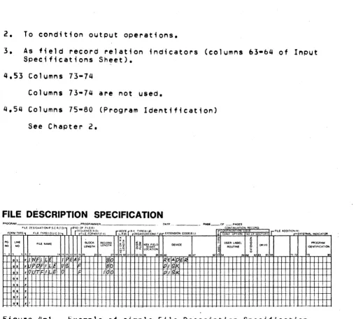
FILE DESCRIPTION SPECIFICATION
PP.()IlRAM PROGRAMMER
OAT' ... - - - - PAGE_OF CC;T:::U~~~ON R CQqO FILE D!SIGNATIOOtP S.C IU.D) rEIIIO OF FIL£/EI
5'EOUENCEtA. 01 MODE RA TYPE(A.lJj'1
ElCTIlN$1ON COOEIE.ll , FII.E "'OO&TIQt.I':~XTERNAlINO'CATOA
FOR~ TYPE FILE TVPEII.O.U C 0) FILE F()q~"TtFI/ 1I •. Rjl) ORGANIZATIONU.T ,JI NT OPT! liO CF E ""S
~
~ §
PO LINE Bl.OCK RECORD «% !5~ USER LABEL ~OGRAM
NO NO FILE NIoME LENGTH LENGTH ~i K\\I~1LD O£V1CE
ROUTINE § CAlVE IDENTIFICATION
~~ iS~ LOCATION 1"2., " , U''i l'it71P 19:i'O 3'-4 1:?1!O'930 31 3~ l
.
"
..
• " "50 .,..
'" "•
F II INFI LE Ilf E~F 0 ~IEA EI~2 • P FI LI~ us 80 IPII S
·
,
.q 'rr F I a F 100 pI, g• • F I
0,. •
t*
-F--
-.7 •
"W-"
,"7 F J .. -.-Example of simpl.e File Description Specification,
I
.1.
f I. . -. . .
0:$ • I
• • F T I If' F II.: P 1 11&
07 F 11:1"1'1
•
•
•0 ' F
,
..
f,I, F -
r-r
.1.
-
I l '.Figure 4-2. Example of continuation line usage in File
Description Spec;f1cat;on.
RPG II SYSTEM
[image:42.613.46.555.56.512.2]CHAPTER 5. EXTENSIUN SPECIFICATIONS
Extension seecifications are needed to describe the record address files, tables, and arrays YOU may use in your job. enter
these specifications o~ the Extension Sheet.
Pre-execution time tables and arrays are describ~d in columns 11-45. Comeile time tables and arrays are described ;n columns 19-45. If an alternatino table or array ;s to be seecified with another table or array, it ;s described ;n columns 46-57 of the same line as the first.
Record address files reQuire entries on the Extension Sheet in columns 11-26.
5.1 Columns 1-2 (eaoe) and 3-~ (Line) See Chapter 2.
5.2 Column b (form Type)
An E must appear in column b.
5.3 Columns 7-10
Columns 7-10 are not used. 5.Q Columns 11-18 (From Fi lename)
Entry
Record AQdress Filename.
Table or Array Filename Blank
The name of the record address f; Ie
def;~e~ on the F;le Descrietion
Soecification Sheet.
Table or array file loaded at pre-execution time.
1. T~ble or array loade~ at compil~tion time
if an entry appears in Number of Entries per Record (columns 33-35).
2. Array loaded at execution t~me (loaded via
[image:43.612.60.578.131.756.2]