66/DPS, 68/DPS
&
DPS 8
DATANET
6641/6651/6661/6678
OPERATION
SUBJECT
System Description, System Operation, and Operating Procedures for the Test and Diagnostic Programs for the 66IDPS, 68/DPS, and DPS 8 DATANET 6641, 6651, 6661, and 6678 Network Processors
SPECIAL INSTRUCTIONS
This revision supersedes Revision 1 of this manual dated October 1978. Due to the extensive nature of the changes incorporated in this revision, change bars have not been used.
ORDER NUMBER
Preface
This manual provides reference information consisting of hardware-oriented descriptive and instructional material for the DATANET 6641166511666116678 family of network processors used with the 66/DJ>S, 68/DPS and DPS 8 systems.
Section 1. System Description
System Components. . . .. 1-1 Central Processor. . . . .. 1-2 Memory . . . 1-2 Cache Memory. . . .. 1-2 Page Control Logic Unit (PCLU). . . .. 1-2 System Bus. . . .. 1-3 Input/Output Multiplexer (10M). . . . . .. 1-4 I/O Bus. . . .. 1-4 Peripheral Interface Adapter (PIA) . . . .. 1-4 System Support Controller (SSC) . . . . .. 1-4 Direct Interface Adapter (DIA). . . .. 1-4 Channel Interface Base (CIB)/
General Purpose Communication
Base (GPCB) . . . .. 1-4 System Software. . . .. 1-5 Built-in Tests . . . . . . .. 1-5
Section 2. System Operation
Power Distribution Unit. . . .. 2-1 Control. . . .. 2-1 Central Processor Control Panel ... , 2-1 Register Display . . . .. 2-3 Octal/Hex Keypad. . . . .. 2-3 Power Switch . . . .. 2-3 Panel Security Keylock Switch . . . .. 2-3 Indicators . . . .. 2-3 Push Buttons. . . .. 2-3
Operation . . . . . .. 2-4 Trap Mode . . . 2~4 Display Memory . . . .. 2-5 Change Memory . . . .. 2-7 Display Registers. . . . .. 2-7 Change Registers. . . . .. 2-8 Stop Program Execution. . . .. 2-8 Execute Single Instruction(s) . . . .. 2-8 Turn On Elapsed Timer. . . .. 2-9 Turn Off Elapsed Timer . . . .. 2-9 Check Timer Operation. . . .. 2-9 Basic Console. . . .. 2-9 Controls . . . . . . .. 2-9 Keyboard. . . .. 2-9 Control Keys. . . . .. 2-10 Autoshutdown . . . .. 2-11 Operation. . . .. 2-11 Applying Power. . . . .. 2-11 Removing Power. . . .. 2-11 Paper Loading. . . .. 2-11 Ribbon Replacement. . . . .. 2-12 Operator Maintenance. . . . .. 2-13 Heavy-Duty Console. . . .. 2-13 Controls and Indicators. . . .. 2-14 Keyboard. . . .. 2-14
Contents
Control Keys. . . .. 2-14 Control Panel. . . . . . .. 2-15 Mechanical Adjustments. . . .. 2-16 Operation. . . .. 2-17 Applying Power. . . . .. 2-17 Removing Power. . . .. 2-17 Forms Loading. . . .. 2-17 Ribbon Cartridge Replacement. . . . .. 2-18 Print Test ... '0' • • • • • • • • • • • • 2-19
Operator Maintenance. . . .. 2-20 Diskette Unit. . . . .. 2-20 Controls . . . .. . . .. 2-20 Operation . . . .. 2-20 Applying Power. . . . . . . .. 2-20 Removing Power. . . .. 2-20 Diskette Unit Loading. . . . .. 2-21 Diskette Unit Unloading. . . . .. 2-21 Operator Maintenance. . . .. 2-21 Care and Handling of Diskette.. . . . .. 2-21 Power Up/Power Down/System Initialization
Procedures. . . .. 2-22 Initial Power Up Procedure. . . .. 2-22 Complete Power Down Procedure. . . . .. 2-22 Normal Power Up Procedure ... 2-22 Normal Power Down Procedure ... 2-23 System Initialization Procedure. . . . .. 2-23
Section 3. Fault Isolation and Diagnostics
Initial Fault Analysis. . . . .. 3-1 Quality Logic Tests. . . .. 3-2
QLT Operating Procedures. . . .. 3-3
Accessing and Checking Boards. . . .. 3-3
Extended QL Ts. . . . . . .. 3-6 Operating Procedures. . . .. 3-7 T&D Guidelines. . . . . .. 3-7 DATANET Offline Tests . . . 3-8 Loading Procedures. . . .. 3-11 Operating Procedures. . . .. 3-12 T&D Options . . . 3-23
END OF MESSAGE (CARRIAGE
PRG xx . . . 3-25 PRINT . . . 3-25 PTAL/RTAL . . . 3-25 RESET . . . 3-26 RUN . . . 3-26 SEQ (BOS Only) . . . . . .. 3-26 SKIP/NOSKIP . . . 3-26 SLOOP /NSLOOP . . . . . . . . . .. 3-26 SNAP /NOSNAP . . . .. . . . . .. 3-26 START . . . 3-26 TEST xx . . . 3-26 TRA xxxxx . . . 3-26 TYPE/PRINT . . . . . . . . . . . . .. 3-26 Dumps . . . 3-27 XDUMP XXXXX YYYYY . . . .. 3-27 Errors . . . . . . . . . . . . . . . . . . . . . . .. 3-27 P AS Standard Error Message. . . . . . .. 3-27 P AS Unexpected Fault Error
Message. . . . . . . . . . . . . . . .. 3-28 P AS Abbreviated Error Message . . . .. 3-28 IDS Standard Error Message. . . . .. 3-28 Explanation of lOS Standard Error
Printout. . . . . . . . . . .. 3-28 Additional lOS Error Messages . . . . . . .. 3-30 Nonstandard Errors. . . . . . . . . . . . . .. 3-30 Extra Interrupt. . . . . . . . . . . . . .. 3-30 Too Many Options . . . 3-31 Halts in DIS Instruction . . . . . . . .. 3-31 L/P Trouble. . . . . . . . . . . . . . .. 3-31 Partial Online (POL) Tests. . . . . . . . . . . . .. 3-31 Loading Procedures. . . . . . . . . . . . .. 3-31 Operating Procedures. . . . . . . . . . . . . .. 3-32 Restrictions/Limitations. . . . . . . . .. 3-32 Bootloading. . . . . . . . . .. 3-36 Normal Execution. . . . . . . .. 3-36 Program Input. . . . . . .. 3-36 Communication with the FNP. . . . . .. 3-36 POL Offline T&D (Monitor) . . . . . . . . .. 3-36 3BT Operator Interface. . . . . . . . . . .. 3-36 Execution Sequence of Primitive,
Loader, I/O Package and
Executive. . . . . . . . . . . . . .. 3-37 Interface Sequence (FNP Initiated). . . .. 3-38
Write To/Read From L66 Console and Print Operations . . . . .. 3-38 Interface Sequence (L66 Initiated) . . . .. 3-38 Options Request at L66 Console. . . .. 3-38 Communications Online Testing
System (COLTS). . . . . . . . . .. 3-39 Loading Procedures. . . . . . .. 3-39 Operating Procedures. . . . . . . . . . .. 3-39
HMLC Subchannel Wraparound . . . .. 3-39 10M Channel Adapters . . . . . . . .. 3-39 Keyboard Type Devices. . . . . . . . .. 3-39
VIP/TTY Devices. . . . . . . . .. 3-39 VIP Direct Access Log-On
Procedure. . . . . . . . . . . .. 3-39 TTY Direct Access Log-On
Procedure . . . . . . . .. 3-40 Non-Keyboard Type Devices. . . . . . .. 3-40 RC /RLP Devices Only. . . . . . . . . .. 3-40 Test Initiation Procedure. . . . . . . .. 3-41
Test End Request . . . .. 3-41 Standard Test Options. . . . . . . . . . . .. 3-41 Special Test Options. . . . . . . . . . . . .. 3-42 Common Control Mnemonics ... 3-42 Special Control Mnemonics. . . . .. 3-43 Notifying the Response Center . . . .. 3-43
Appendix A. System Configuration Form
Appendix B. Channel Fault Status Bit Definitions
Appendix C. Programming Considerations
CPU-I/O Conflict on DN66 . . . . . . . . .. C-l Instruction Counter during Faults. . . . . . .. C-l New Instructions. . . . . . . . . . . . . . . . .. C-l DN66 T&D Instructions. . . . . . . . . .. C-l
CAQC - Copy Accumulator and
Quotient to Channel 533200s . . ... C-l Summary. . . . . . . . . . . . . . .. C-l Indicators . . . C-2 CCQ - Copy Channel to Quotient
(533300s ). . . . . . . . .. C-2 Summary. . . . . . . . . . . . .. C-2 Indicators. . . . . . . . . . . . .. C-2 eRA - Copy Register to A
(7332XXs ) . . . . . . . . . . . . . . . . . .. C-2 CAR - Copy A to Register
(1332XXs ) . . . .. C-2 Summary . . . C-2 Page Address Table Update. . . . . . . .. C-3 PIA Base Address . . . . . . . . . . . . . .. C-4 PIA Transfer Timing Errors. . . . . . .. C-4 Absolute Addressing. . . . . . . . . . . .. C-4 Store Mask Register. . . . . . . . . .. C-4 Initializing HMLC . . . . . . . . . . . . . . . .. C-4 Optional ASYNC Baud Rates and
European Baud Rates . . . . . . . . . .. C-5 Parity Generation for Communication
SUbchannels . . . C-5 Current Loop Adapter . . . C-5 Break from ASYNC Terminals . . . C-5 Last Communications Character
Transmission. . . . . . . . . . . .. C-6 Subchannel ID Codes . . . C-6 Auto Baud Detection (13.4.5 Baud). . . . . .. C-6
Figures
1-1 DATANET Network Processor. . .. 1-1
1-2 DATANET System Components. .. 1-3
2-10 Paper Positioning Controls ... 2-16 3-16 I/O T&D (PRG M2) Console
2-11 Paper Loading . . . 2-18 Printout . . . 3-21
2-12 Ribbon Cartridge Replacement .... 2-19 3-17 Console Typeout for Multi
2-13 Diskette Media Handling ... 2-21 I/O T&D MI ... 3-22
3-1 Fault Isolation Overview ... 3-1 3-18 DN66 T&D Memory Map ... 3-22
3-2 Opening Control Panel ... 3-4 3-19 Example of Host Console
3-3 Board Locations . . . 3-4 Typeout for POL T&D lOS ... 3-32
3-4 QL T and Error LED Locations .... 3-5 3-20 Example of Host Console Typeout
3-5 T&D Overview . . . 3=8 for POL T&D BOS ... 3-34
3-6 BOS Console Typeout Including 3-21 Example of Host Console Typeout
Cache PRG 80 ... 3-13 for POL T&Ds 80 (Cache)
3-7 Memory T&S 86 Testing 64K and 86 (Memory) ... 3-35
Memory . . . 3-14 r"I ...
\..1-.1 Subchannel ID Codes ... C-6
3-8 Console Typeout for Console T&D
CO . . . 3-15
3-9 Console Typeout for DIA T&D, \
Tables
DA and DI. . . 3-16
3-10 . Console Typeout for EIA-HMLC 2-1 Summary of Control Panel
T&Ds HI-H4 ... 3-17 Operations . . . 2-6
3-11 Console Typeout for T&D HI with 2-2 Multicopy Adjustment Level ... 2-17
Active Channel Table Printed 3-1 QL T Fault Table . . . 3-3 Out . . . 3-18 3-2 CP Error Light Combinations ... 3-5
3-12 Console Typeout for BSC-HMLC 3-3 10M Error Light Combinations .... 3-5
T&Ds HA, HB, H5, H6 ... 3-19 3-4 PCLU Error Light
3-13 Console Printouts for HMLC-HDLC Combinations ... 3-6
T&Ds H7-H9 ... 3-20 3-5 DATANET Offline Test &
3-14 Console Typeout for Extended Diagnostic Programs ... 3-9
Addressing T&D EA ... 3-21 3-6 DN66 Configuration Chart ... 3-18
3-15 Console Typeout for Diskette B-1 Channel Fault Status Bit
Section
1
System Description
The DATANET Network Processor encompasses a whole family of compact, powerful net-work processors which can provide Honeywell 66IDPS, 68/DPS and DPS 8 systems with large-volu..TIle network communications power. Based on Honeywell's minicomputer technology for reduced space, greater reliability, and easier serviceability, the DATANET is logically compat-ible with the system software and user-generated programs of the DATANET 6600 family of network processors (see Figure 1-1).
The DATANET provides the variety of interfaces required by the elements and protocols ofa distributed system, as well as a facility for dialog with the central system. By performing the tasks of message management and message handling, the processor relieves the central system for other processing functions. The resources of the central system are called upon only when the message is submitted for information processing. However, some networking functions (e.g., a message switch) can be accommodated by the processor without any involvement of the host processor.
SYSTEM COMPONENTS
• Central Processor
• Memory
• Cache Memory (if present)
• Page Unit (if present)
• System Bus
• Input/Output Multiplexer
• 110 Bus
• Peripheral Interface Adapter (if present)
• System Support Controller
• Direct Interface Adapter
• Channel Interface Base (CIB)/General Purpose Communication Base (GPCB)
CENTRAL PROCESSOR
The central processing unit is a solid-state, interrupt-driven, 18-bit machine operating asynchronously under firmware control. Its instruction repertoire is designed for efficient processing of a wide variety of communication network applications and is fully upward-compatible with the instruction sets of other Level 66 or Level 68 network processors. The processor design accommodates a high-speed cache memory which, together with the appropriate configuration and optimum instruction mix, provides an execution rate of up to 1,000,000 instructions per second - nearly double that of other DAT ANETs.
Standard features include a flexible bus structure, power failure/automatic restart, EDAC (Error Detection and Correction) memory, processor faults (internal interrupts), program inter-rupts (external interinter-rupts), a real-time clock, and a watchdog timer.
MEMORY
The high-speed, random access, semiconductor memory subsystem performs all storage func-tions without restricfunc-tions on address sequences, data patterns, or repetition rates. Memory features include single- and double-fetch, self-contained initialize and refresh logic, and stan-dard EDAC functionality. The DATANET may be configured with up to 256K words maximum.
CACHE MEMORY
The cache memory (if present) provides intermediate high-speed storage, which improves the performance of the central processor unit by decreasing the time required to receive (i.e., fetch) instructions and data from main memory. This decrease in time is achieved both by anticipatory main memory reads and by storage of previously used data and instructions for future iterations of the currently executing program.
The cache memory contains copies of selected (recently referenced) memory locations. It has a system bus interface which allows it to make memory read references on behalf of the central processor unit and to monitor the system bus, copying main memory write data if it currently contains a copy of the location addressed. The cache memory also has a private interface allowing it to communicate with the central processor unit to which it is dedicated. It receives memory read requests across this interface, thereby becoming committed to locate the data for the central processor unit in its local cache array or in main memory. In either case, the request.ed data is delivered to the CP for processing. The cache memory overlaps its read requests to main memory and is invisible to software.
PAGE CONTROL LOGIC UNIT (PCLU)
n
PERIPHERALI
INTERFACE ADAPTER
I
I
SYSTEM~
SUPPORT CONTROLLER
II) ::>
lD II)
::>
I-lD 0.. ::>
:a: 10M
I-w ::>
I- 0
II) ;::
DIRECT
32K-WORD >-II) ::> INTERFACE HOST SYSTEM MEMORY 0..
ADAPTER
~
32K-WORD MEMORY
CIB/GPCB
I
UP TO 8 LINESADDITIONAL 32K-WORD MEMORY MODULES
U
ADDITIONAL CIB/GPCBsFigure 1-2. DATANET System Components
SYSTEM BUS
The system bus allows communication between the CP, memory, and the input/output multiplexer. The system bus is bidirectional, permitting any two units to communicate with each other at a given time. The transfer of information between units forms a master/slave relationship (i.e., the unit requesting and receiving access to the bus becomes the master; the unit being addresed by the master becomes the slave). If the communication requires a response, the responding slave unit assumes the role of master and the requesting unit (previous master) becomes the slave.
All information transfers are from master to slave and each transfer is referred to as a bus cycle. This cycle is the period of time in which the requester (master) asks for use of the bus. Ifno other unit of a higher priority is making a bus request, use of the bus is granted to the requester (master). The master then transmits its information to the slave and the slave acknowledges the communication.
informa-The granting of time on the bus is done on a priority basis. If two components on the bus simultaneously request time, the one with the higher priority will be granted the time. This priority is determined by the physical position of the component on the bus. On the system bus, the lower the physical position, the higher the priority. The priority is established relative to the rate at which the components transfer and/or receive data.
INPUT/OUTPUT MULTIPLEXER (10M)
The 10M performs all operations required for the transfer of data between input/output devices and the DATANET memory. The advanced technology of the DATANET gives it a transfer rate of2,000,000 bytes per second. The 10M is the interface between the system bus (to processor and memory) and the I/O bus (to which the various I/O devices are connected). Attached to the I/O bus are the System Support Controller for the console and diskette; the Direct Interface Adapter (DIA), which provides connection to the central system; the Channel Interface Bases/General Purpose Communication Bases, through which the network devices enter the system; and the Peripheral Interface Adapter (PIA), which provides connection to the central system's mass storage processor. Internally, the 10M operates asynchronously in an interrupt-driven fashion.
I/O BUS
The I/O bus is basically the same as the system bus, differing only in the units that interface on the bus and the operations that take place between the units.
The I/O bus allows communication between the I/O controllers and adapters to the system through the 10M. Operations on the I/O bus are initiated by the 10M or DIA, depending on the activity that is required.
The components on the bus are positioned relative to their priority. The highest priority component is placed at the bottom of the I/O bus next to the 10M; the lowest priority component is placed at the top of the I/O bus farthest from the 10M. The I/O bus is at the top of the chassis; the system bus is at the bottom of the chassis.
PERIPHERAL INTERFACE ADAPTER (PIA)
The PIA, which is an option, provides the interface between the DATANET input/output bus and the central system's mass storage processor. Up to two PIAs can be installed in a system; however, the software will utilize only one PIA. The PIA provides the disk access required by the NPS (Network Processing Supervisor) software.
SYSTEM SUPPORT CONTROLLER (SSC)
The SSC is a peripheral controller for the console and diskette. The console is used to control and monitor DATANET activity. The diskette unit is used to load the system offiine test and diagnostics (T&Ds).
DIRECT INTERFACE ADAPTER (DIA)
The DIA provides the interface between the DATANET input/output bus and the Level 66 or 68 host system for the transfer of data and control i!lJormation, The DATA_NET cont.rols all transactions and normal data transfer activities through the DIA except for ~~initiate bootload" or program interrupts from the central system. A second DIA can be installed in a system; however, the software will utilize only one DIA.
CHANNEL INTERFACE BASE (CIB)/GENERAL PURPOSE COMMUNICATION BASE (GPCB)
The CIB/GPCB enables low-, medium-, and high-speed data communications terminals and
communica-tions control procedures. The CIB/GPCB enables the connection of up to eight communicacommunica-tions lines depending upon the functions required. Additional CIB/GPCBs can be configured.
The CIB/GPCB accepts up to 4 (or up to 2 double-size) communications adapters in any combination. A dual channel can connect two lines. The various communications adapters are as follows:
• 20 rnA Current Loop - dual • RS-232-C Synchronous - dual
e RS-232-C Asynchronous - dual
• Automatic Call Unit - dual
• MIL-STD-188C - broadband
• MIL-STD-188C - synchronous
• MIL-STD-188C - asynchronous, dual
• MIL-STD-188C - HDLC
• Bisynchronous - dual
• Broadband
• Broadband CCITT -V.35
• HDLC - voicegrade
• Bisynchronous - broadband
• Broadband - HDLC
• HDLC CCITT-V.35
• Direct Connect - asynchronous • Direct Connect - synchronous Note:
Direct connect capability is via cable.
SYSTEM SOFTWARE
Either the Remote Terminal Supervisor (GRTS II3I; GRTS I! ReI. 1) or the Network Processing Supervisor (NPS), Release NT2 (or greater), depending upon network require-ments, can control the operation of the DAT ANET Network Processor and provide a software interface to the central system. GRTS III! is a high-performance, low-overhead system for users who do not need the full networking capabilities of NPS. Both systems support remote job entry, message concentration, transaction processing, and time sharing dimensions. NPS offers completely unique device control parameterization facilities and other outstanding customization features. By utilizing a DATANET Network Processor channel to the central system's mass storage processor, NPS can provide journalization and message switching capabilities.
BUILT-IN TESTS
A portion of the fIrmware on the CP, memories, 10M, Channel Interface Bases, and System Support Controller boards is reserved for two types of hardware verification routines called Quality Logic Tests (QLTs) and Extended QLTs (E-QLTs). Their purpose is to verify basic data paths and to provide a go/no-go visual identification of a hardware failure.
Channel Interface Base boards, each of the eight lines has program-usable loop-back of data transmit to data receive to facilitate diagnosis.
Section 2
System Operation
DATANET Network Processor operation is controlled by the software except for occasional operator interventions. The operator duties and responsibilities in regard to the DATANET system are normally governed by the rules and regulations in effect for the Series 60 Level 66 or Level 68 system on the site. All subsystem maintenance required on the equipment is performed by the Honeywell Field Engineer, except routine site cleaning which is the responsibility of the operating personnel. The operator is also required to execute the E-QLTs and to load and run the system test and diagnostic programs. These procedures are explained in Section 3.
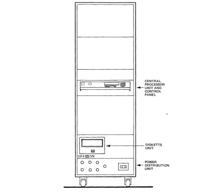
To operate the DATANET, the operator must know how to operate the following controls and equipment (see Figure 2-1):
• Power Distribution Unit
• Central Processor Control Panel
• Console (Basic or Heavy-Duty)
• Diskette Unit
It is also the operator's responsibility to routinely do the following:
• Power up the system
• Initialize the system
• Power down the system
POWER DISTRIBUTION UNIT
For the system to operate, all power supplies and the Power Distribution Unit (PDU) must be turned on.
Power is applied to the system in the following order:
1. Power Distribution Unit
2. Central Processor Unit
3. Peripherals (Console and Diskette Unit)
The PDU is located in the bottom of the rack (see Figure 2-1).
CONTROL
ON/OFF Switch The operator must set the PDU ON/OFF switch to the ON position.
This action must be taken before power is applied to the central processor.
CENTRAL PROCESSOR CONTROL PANEL
The DATANET has a control panel that provides for the following (see Figures 2-1 and 2-2):
• Powering up and initializing the system
• Starting and stopping the CP
• Entering and displaying registers/memory information
• Single stepping a program
• Bootloading a program
PllW£I
I
~D
0II
II
E3
OFFCDON
0 0 0
0 0 0
0
~U
J
0
la:nl
ld
CEN PRO
TRAL CESSOR
AND TROL EL . - UNIT
CON PAN
DISK ETTE
T
UNI POW ER
RIBUTION
~DIST
[image:13.620.73.496.35.413.2]UNIT
Figure 2-1. DATANET Rack Layout
[image:13.620.77.489.453.675.2]REGISTER DISPLA Y
The register display is divided into two sections - one labeled LOCATION and the other CONTENTS.
• LOCATION - A 2-digit display which indicates the specific CP register selected. The display consists of a left hexadecimal digit indicator and a right octal digit indicator.
• CONTENTS - A 6-digit octal display which indicates the contents of the selected register.
OCTAL/HEX KEYPAD
The octallhex keypad consists of 16 keys and is divided into two groups - an octal digit key cluster and a hex alphabetic key cluster.
• Octal Digit Key Cluster - The digits 0-7 are used to enter address or data into the CONTENTS and LOCATION displays.
• Hex Alphabetic Key Cluster - The digits 8-F are used to enter digits into the LOCA-TION display.
POWERswrrCH
The power switch is used to apply or remove ac power to or from the system. In the up position, power is on; in the down position, power is off.
PANEL SECURITY KEYLOCK SWITCH
The left (locked) position disables panel switches and push-buttons except for POWER. The right (unlocked) position enables panel switches and push buttons.
INDICATORS
The indicators are long-life, light-emitting diodes (LEDs).
DC ON
CHECK
INT
CP
CHANGE
TRAP
WRITE
READ
STOP/STEP
READY
PUSH BurrONS
CLR
(Master Clear)
S (Select)
C
Indicates that dc power is applied to the system.
Indicates that the system is performing or has been unable to success-fully complete its QLTs after a system initialization.
Indicates that the control panel interrupt is active. If indicator stays lit, the system is in a ((hung" or non-interruptible ((fault" state. (Refer to ((System Initialization Procedure").
Indicates that the CP is executing instructions.
Indicates that key cluster information may be entered into the CON-TENTS display.
Indicates that the CP is in the trap mode.
Indicates that the CP is in the write mode.
Indicates that the CP is in the read mode.
Indicates that the CP is in the stop mode.
Indicates that the CP is in the ready mode.
Press to initialize the system.
Press to allow key cluster information to be entered into the LOCATION display.
T
(Trap)
w
(Write)
R
(Read)
S
(Stop/Step)
R (Run)
E
(Execute)
OPERATION
Press to place the CP in a constant panel interrupt mode after every interruptible instruction to allow the CP to stop for a variety of predetermined comparisons.
Note:
Not for normal operator use; for reference purposes only.
Press to place the, CP in the write mode so that CONTENTS informa-. tion is written into CP registers or into main memoryinforma-.
Press to place the CP in the read mode so that the contents of the CP registers or main memory are read and displayed in the CONTENTS display.
Press to remove the CP from the run, ready, write, or read mode and place it into the stop mode.
Press to place the CP in the ready mode.
Press to place the CP in the run mode, allowing it to execute instruc-tions and interrupts according to its internal state.
The functions that can be performed from the control panel are: displaying/changing memory, displaying/changing registers, executing single instructions, restarting programs, and master clearing the processor. Before any operation is performed from the control panel (except for powering up/down), it must first be unlocked u~ing the panel security key.
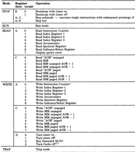
Table 2-1 lists the various operations that can be performed via the operator control panel. The table lists the five operating modes, all the DATANET registers that an operator can select, and the resulting operation that can be performed.
TRAP MODE
Trap mode is a special mode which enables the field engineer or a programmer to stop on an address or a data pattern.
It is possible to trap on a special value of the instruction counter, index register 1, 2, or 3, A register, Q register, indicator register or a given value at location ~~X" in memory.
When the specified condition is met the CP will go into stop mode. However, if an interrupt occurs, the CP (ifnot in inhibited mode) will continue operation.
CAUTION
Trap mode causes the DATANET system to run 10 times slower, and heavily loaded systems may cause other unknown problems.
Examples:
Instruction Counter: stop ifIC=001000
Select AO: change, 001000~ trap, execute.
Index Register: stop if X = 001000
Select Al (respectively A2, A3), change, 001000, trap, execute.
A Register, Q Register, Indicator Register: stop if _ _ =001000
Select A4 (respectively A5, A6) change, 001000, trap, execute.
Main Memory: stop if location 000100= 123456
Notes:
1. Ifrunning a program and compare is made the STOP/STEP LED will come on.
2. When the CP is in stop mode, if an interrupt comes along it could send the CP into run mode again.
3. CP can only compare addresses between interruptible instruction. For example:
1000 1001 1002
10010
10020
Any attempt to trap on instruction counter=10010 will fail because all the above instructions except LDA are non-interruptible. Conversely, if the LDI was loading the indictors with the ~~compared" value, the CP would stop only at the end of the LDA at 10020 and the instruction counter would indicate 10021 because it would be the first interruptible instrution where the condition is met.
DISPLAY MEMORY
Any memory location may be accessed and displayed from the control panel by entering the memory address to be accessed into register CO (actually memory location 000634) and then reading or writing that location by selecting C 1. Sequential memory locations can be read or written by selecting C2 instead ofC1 for incrementing memory locations, or C3 for decrement-ing memory locations.
1. Press §.elect.
2. Press octallhex-pad keys CO. This enters the 2-digit selection code for the memory address register.
3. Press £hange. This places the processor in change mode preparatory to keying in the address of the memory location to be displayed. The CHANGE indicator lights when the Change control key is pressed.
4. Key in, via the octal hex-pad keys, the 6-digit octal value representing the address of the memory location to be read. This address appears in the CONTENTS field of the REGISTER display.
5. Press Write.
6. Press Execute. 7. Press Select.
8. Key in, via the octallhex-pad keys, the 2-digit selection code for the desired memory data register (C1, C2, C3, C4, C5, C6, or C7).
TABLE 2-1. SUMMARY OF CONTROL PANEL OPERATIONS Mode Register Operation
(hex) (octal)
STOP B 0 Bootstrap with timer on 1 Bootstrap with timer off
A,C, Step submode - executes single instructions with subsequent pressings of or D Stop key
RUN Run mode
READ A 0 Read Instruction Counter
1 Read Index Register 1 2 Read Index Register 2 3 Read Index Register 3 4 Read Accumulator 5 Read Quotient Register 6 Read Indicator/Select Register 7 Display parity error
C 0 Read ~~AOR" unpaged
1 ReadMM
2 Read MM unpaged AOR + 1 3 Read MM unpaged AOR - 1 4 Read ~~AOR" paged
5 Read MM paged
6 Read MM paged AOR + 1 7 Read MM paged AOR - 1
WRITE A 0 Write Instruction Countera
1 Write Index Register 1 2 Write Index Register 2 3 Write Index Register 3 4 Write Accumulator 5 Write Quotient Register 6 Write Indicator/Select Register
C 0 Write "AOR" unpaged 1 Write MM unpaged
2 Write MM unpaged AOR + 1
3 Write MM unpaged AOR - 1 4 Write "AOR" paged
5 Write MM paged
6 Write MM paged AOR + 1
7 Write MM paged AOR - 1
D 0 Turn timer on 1 Turn timer ofFi 2 Run Extended QLTsa 3 Turn Cache offa, b
TRAP Trap mode
aDo not perform this operation while running system software. b'fhis operation will also ligpt the CHECK LED.
Notes:
1. The operator should never write into register C4 and then read/write into any of the following registers: Cl, C2, C3, C5, C6, or C7. Rather, write into CO, then read C4 for the correspondence bet\:lleen paged and unpaged addresses.
2. Memory address register CO is at times loaded with an invalid memory address by the T&Ds; therefore, never perform a read operation of CO before writing in a valid memory address; otherwise, an illegal memory operation fault will occur.
10. Press Execute. This loads the data contents of the selected memory location into the selected register and displays it in the CONTENTS field of the REGISTER display.
Note:
If an increment or decrement memory data register code was entered in step 8, subsequent pressings of the Execute key will increment or decr:ement the display as appropriate.
CHANGE MEMORY
Any memory location may be accessed and changed from the control panel. As mentioned previously, the memory address register (CO) is the only visible register that can be used to access memorj locations from the control panel.
The following procedure describes a method for changing the contents of one memory location and, as an option, changing the contents of subsequent memory locations.
1. Press Write. This places the processor in write mode and instructs that the contents of the me~ory location addressed by the memory address register (CO) are to be changed. The WRITE indicator lights when the !yrite control key is pressed.
2. Press Select. This places the processor in select mode as a necessary preliminary to
selecti~g the memory address register. This step is not necessary unless the CHANGE indicator is lit.
3. Press octal/hex keys CO. This enters the 2-digit selection code for the memory address register. Digits CO appear in the LOCATION field of the REGISTER display.
4. Press Change. This places the processor in change mode preparatory to keying in the address of the memory location to be changed. The CHANGE indicator lights when the Change control key is pressed.
5. Key in, via the octallhex keys, the 6-digit octal value representing the address of the memory location to be changed. This address appears in the CONTENTS field. of the REGISTER display.
6. Press Execute.
7. Press Select. This returns the processor to select mode as a necessary preliminary to selecting the memory data register. The CHANGE indicator turns off when the §elect control key is pressed.
8. Press octal/hex keys. This enters the 2-digit selection code for the memory data register. The digits appear in the LOCATION field of the REGISTER display.
9. Press Qhange. This places the processor in change mode preparatory to keying in the data for the memory location that is to be changed. The CHANGE indicator lights when the Qhange control key is pressed.
10. Key in, via the octal/hex keys, the 6-digit octal value representing the new data that is to be entered into the memory location to be changed. The data entered appears in the CONTENTS field of the REGISTER display.
11. Press Execute. This loads the new data contents into the selected memory location.
12. If successive memory locations are to be changed, repeat steps 10 and 11 for each sequential memory location to be changed.
DISPLAY REGISTERS
The contents of any of the visible registers may be displayed on the control panel. A register may be displayed when the processor is in any mode.
The following procedure describes a method for displaying the contents of a register. The same procedure applies regardless of the processor mode.
2. Key in, via the octal/hex keys, the 2-digit selection code for the desired register to be displayed. The selection code appears in the LOCATION field of the register display.
3. Press Bead.
4. Press Execute. This displays the data contents of the selected register in the CONTENTS field of the REGISTER display.
CHANGE REGISTERS
The contents of software-visible registers may be changed from the control panel. The following procedure describes a method for changing the contents of a register.
1. Press Write. The WRITE indicator lights when the Write control key is pressed.
2. Press Select. This places the processor in the select mode as a necessary preliminary to selecdii.g the register to be changed.
3. Key in, via the octal/hex keys, the 2-digit selection code for the desired register to be changed. The selection code appears in the LOCATION field of the REGISTER display.
4. Press Change. This places the processor in change mode preparatory to keying in the data to the-register that is to be changed. The CHANGE indicator lights when the Change
control key is pressed.
-5. Key in, via the octallhex keys, the octal value representing the new data that is to be entered into the selected register. The data entered appears in the CONTENTS field of the REGISTER display.
6. Press Write.
7. Press Execute.
STOP PROGRAM EXECUTION
While a program is running, program execution can be stopped at any time by pressing Stop and Execute. The STOP/STEP indicator lights and the RUN, READY, and CP indicators
turn
off. Wheri this action is initiated, the processor completes the execution of the current instruc-tion and enters the stop mode. After this mode is achieved, the following condiinstruc-tions exist.1. The processor is automatically placed in a step mode (i.e., ready to execute one instruction ata time).
2. The instruction counter (AO) contains the instruction to be executed next.
Note that when a program is running and a DIS instruction is encountered (RUN indicator remains lit, but the CP indicator turns oft), the processor does not enter the stop mode, but rather
enters an id.le condition. In this condition, the DIS instruction is continuously re-executing and the processor is subject to external interrupts, etc. The .§.top control key must be pressed in order to set the processor into a stop mode.
EXECUTE SINGLE INSTRUCTION(S)
When running a program, it may be desirable to stop processing and step through the execution of one or more instructions. This procedure is accomplished from the control panel, as follows:
1. Press Stop and Execute. (Refer to the previous procedure, UStop Program Execution," for
relev~t inform";tion concerning processor/panel status after a stop mode is achieved.) 2. Determine whether the processor has stopped at a point (address) from which you wish to
begin executing single instructions. Display and view the contents of the instruction counter (AO) using the procedure previously described for displaying registers.
TURN ON ELAPSED TIMER
1. Press §elect. 2. Key-in, DO.
3. Press Write.
4. Press ~xecute. (Timer is now turned on.)
TURN OFF ELAPSED TIMER
1. Press Select.
2. Key-in,D1. 3. Press Write.
4. Press !dxecute. (Timer is now turned off.)
CHECK TIMER OPERATION
1. Press Select.
2. Key-in, CO.
3. Press Qhange. 4. Key-in, 000451.
5. Press Select.
6. Press Write.
7. Press Execute
8. Key-in, C1. 9. Press Read.
10. Press Execute several times. Note that the display should change each time Execute is pressed. Ifnot, timer is turned off. However, if the timer is not running and has not been turned off (assuming the control panel is operational), either the 10M is hung or a breakdown in communication between the 10M and CP has occurred since the last Master Clear. To determine if the 10M is hung, attempt to turn the timer on twice from the control panel. If the INT indicator does not light after the second Execute, the 10M is
not hung.
BASIC CONSOLE
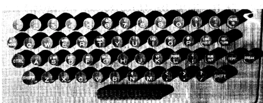
The basic console (see Figure 2-3) has a 64-character ASCII code set, prints at 10 characters per second and has 72 print positions. It uses a paper roll 8.5 in. (21.6 cm) wide and 5 in. (12.7 cm) in diameter. The basic console is also equipped with an automatic shutdown feature which can extend console life and reduce maintenance costs.
CONTROLS
Console controls are described below.
KEYBOARD
Figure 2-3. Basic Console
Figure 2-4. Keyboard Layout
CONTROL KEYS
The control keys used for normal teleprinter operation include the following:
LINE/OFF/LOCAL This switch, located on the right side of the front panel, is the main power switch for the device.
• In the OFF position, the device is disabled.
• In the LINE position, the device is enabled to send to or receive from the central processor in the full-duplex mode.
[image:21.621.75.499.372.539.2]CTRL (Control)
SHIFf
LINE FEED
RETURN
RUB OUT
REPr (Repeat)
ALTMODE
BREAK
AUTOSHUTDOWN
Pressing the control key does not generate any code, but allows some of the keys to generate nonprintable function characters. When CTRL is pressed, inappropriate keys (mostly those having uppercase char-acters) are locked out.
Pressing the SHIFT key causes all the ASCII keys to generate their associated uppercase characters.
Pressing the LINE FEED key causes the paper to advance vertically. The carriage does not return to the left margin (see RETURN).
Pressing the RETURN key generates a carriage return character. The type unit returns to the left margin but the paper does not advance vertically. The RETURN key should be used with the LINE FEED key to advance the paper vertically.
Pressing the RUB OUT key generates an octal code 377 each time. For example, by backspacing a paper tape and punching RUB OUT over an error, the error is converted to octal code 377 and is ignored upon subsequent reading.
Pressing the repeat key simultaneously with another key causes the normal action of the other key to be repeated as long as the two keys are pressed.
Pressing the ALT MODE key produces an octal code of 375. When ALT MODE is pressed simultaneously with the CTRL key, an octal code of275 is produced.
Pressing the BREAK key interrupts output on the console from the system.
The basic console is equipped with an automatic shutdown feature which turns the device off
in the absence of activity from the central processor for a I-minute period (when operating with the control switch set to the LINE position).
The central processor activates the console whenever activity is awaiting transmittal. The operator can also activate the device by pressing the BREAK key.
OPERATION
Operating procedures for the teleprinters are described below.
APPLYING POWER
Set LINE/OFF/LOCAL switch to LINE or LOCAL position.
REMOVING POWER
Set LINE/OFF/LOCAL switch to OFF position.
PAPER LOADING
To install a new paper roll, follow these directions. Figure 2-5 illustrates the components discussed in the text.
1. Set LINE/OFF/LOCAL switch to OFF position.
2. Install a new paper roll in the unit by inserting the spindle into the new paper roll.
4. Raise the clear plastic lid over the typing unit.
5. Fold and crease the leading edge of the paper to present a smooth threading edge for feeding.
6. Release the tension of the typing unit platen by moving the pressure lever.
7. Push the paper under the platen roller as far as possible and move the pressure lever backwards to reapply roller tension.
8. Push the platen knob to feed the paper forward until it can be passed under the unit paper guide.
9. Ifnecessary, again release the tension on the pressure rollers and straighten the paper.
10. Reapply roller tension.
11. Close the cover.
12. Set LINE/OFF/LOCAL switch to LINE or LOCAL position.
ROLL OF PAPER
This illustration from Technical Manual Models 32 and 33 Tele-typewriter Sets Keyboard Send-Receive (KSRI Receive-Only (ROI Automatic Send-Receive (ASRI. Copyrighted by Teletype Corpo-ration; used with permission.
Figure 2-5. Installation of Paper Roll
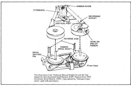
RIBBON REPLACEMENT
To install a new ribbon, follow these directions. Figure 2-6 illustrates the components discussed in the procedures.
1. Set LINE/OFF/LOCAL switch to OFF.
2. Raise the cover lid.
3. Pull both spools off the friction spindles.
4. Wind the ribbon onto one of the spools. 5. Discard the old ribbon.
6. Unwrap a new ribbon and engage the hook ai ihe end oi the ribbon in the hub of the empty spool.
7. Wind a few iurns oiribbon onto the empty spool in the dir~ection indicated by the arrow in the hub. Be sure that the reversing eyelet has been wound onto the empty spool.
8. Place the spools on the shafts so that the ribbon feeds to the rear from the right side of the right spool and from the left side of the left spool.
9. Turn each spool slightly until the spool driving pin engages the hole in the spool.
10. Guide the ribbon around the right vertical post and throygh the slot in the reverse arm.
11. Place the ribbon in the ribbon guide behind the typewheel.
13. Rotate the spool to take up any slack.
14. Set LINE/OFF/LOCAL switch to LINE.
TYPEWHEEL
SPOOL DRIVING PIN
HOOK ON ENDOF RIBBON
[image:24.618.111.546.79.370.2]This illustration from Technical Manual Models 32 and 33 Tele-typewriter Sets Keyboard Send-Receive (KSR) Receive-Only (RO) Automatic Send-Receive (ASR), Copyrighted by Teletype Corpo-ration; used with permission.
Figure 2-6. Ribbon Installation
OPERATOR MAINTENANCE
Operator maintenance includes such preventive maintenance as normal checking and clean-ing performed periodically on a routinely scheduled basis. This maintenance will keep the teleprinter in the best operating condition.
The following list is a general guide to operator maintenance:
• Always plug the device into a 3-wire grounded outlet.
• Ensure that all covers are secured and closed during operation.
• Never operate the teleprinter without paper.
• Avoid leaning on or placing objects on any part of the teleprinter.
• Turn the power OFF before replacing paper or ribbons.
• Never put food or beverages on or near the device. • Keep the outside covers clean and free of debris.
• Clean and dust the inside areas of the print, punch, and reader mechanisms.
HEAVY-DUTY CONSOLE
CONTROLS AND INDICATORS
Console controls and indicators are described in the following paragraphs.
KEYBOARD
The 64-character keyboard is shown on Figure 2-8.
"
':'\:\:';'",:,'\'~';:;;:::\'\':',"~;\:'
\..~:\;'? ~:\0:. : .. ~,,~,~~ :...
Figure 2-7. Heavy-Duty Console
Figure 2-8. Keyboard Layout
CONTROL KEYS
The control keys used for normal operation include the following:
CTL Pressing the CTL (control) key generates the control function codes of
the ASCII code set.
RPT Pressing the RPT (repeat) key simultaneously with another key
LF
BRK
RETURN
DEL
CLR
HERE IS
ESC
CAPWCK
CONTROL PANEL
Pressing the LF (line feed) key advances the last line upwards one line position.
Pressing the BRK (break) key allows the operator to generate an interrupt to the system.
Pressing the RETURN key causes the carriage to return to the first character position of the same line that it is positioned on.
Pressing the DEL (delete) key together with the SHIFT key generates an ASCII hex code of IF.
Pressing the CLR (clear) key generates an ASCII hex code ofOC. The same code can also be generated by pressing the CTL key together with the L key.
This key is not used.
Pressing the ESC (escape code) key generates an ASCII hex code of lB. The same code can also be generated by simultaneously pressing the CTL, SHIFT, and [ (left bracket) keys.
Pressing the CAP LOCK key locks the keyboard in an uppercase-only operating mode.
The console control panel is shown in Figure 2-9. The controls and indicators include the following:
MAIN POWER
START
STOP
LOCAL
TEST
READY
STANDBY
LOCAL
OFFLINE
SHIFf
Paper-Out Sensor
Pressing this switch (located on the rear of the console) applies or removes power to or from the device.
Pressing the START button causes a transition from the standby state to ready state and enables communication with the system.
Pressing the STOP button causes a transition from the ready state to standby state. It is also used to reset to local condition.
Pressing the LOCAL button allows the console to be used indepen-dentlyfrom the system (STANDBY lights).
Pressing the TEST button (preceded by LOCAL) causes a printout of the complete (uppercase and lowercase) character set. Refer to PRINT TEST procedures.
Indicates that the console is in ready state, logically connected to the system, and ready to communicate with the system.
Indicates that the device is powered up, physically connected to the system, but not ready to communicate with the system.
Indicates that the console is in the local mode and can be operated independently of the system.
Indicates that the console is powered up but not physically connected to the system.
Pressing the SHIFf key with an applicable key generates its asso-ciated uppercase character.
Figure 2-9. Control Panel
MECHANICAL ADJUSTMENTS
There are several mechanical adjustments located in the printer mechanism (Figure 2-10) for the control of printing and paper feeding.
Paper Width Knob
Paper Advance Knob
Multicopy Adjust-mentLever
U sed to lock/unlock the right tractor so it may be adjusted to accom-modate the paper width.
Used to manually advance paper one or more lines.
Used for manual adjustment of the platen in relationship to the print head. The lever is designed with five individual settings (1 through 5) which correspond to the thickness of the applicable form (single through 4-ply). The lever should be checked whenever forms are changed or when the device is turned on to ensure the proper setting.
See Table 2-2.
OPERATION
TABLE 2-2. MULTICOPY ADJUSTMENT LEVEL Media Thickness
0.07 mm to 0.11 mm (0.003 in. to 0.0043 in.) 0.12 mm to 0.22mm (0.0051 in. to 0.0087 in.) 0.23 mm to 0.32 mm (0.0091 in. to 0.0126 in.) 0.33 mm to 0.42 mm (0.0130 in. to 0.0165 in.) 0043 rmn to 0.52 mm (0.0169 in. to 0.0205 in.)
Lever Position 1
2
3
4
5
Operating procedures for the heavy-duty console are described below.
APPLYING POWER
1. Set power switch on rear of console to ON (STANDBY lights).
2. Refer to ~~Forms Loading" procedure; otherwise press the START button (READY lights).
REMOVING POWER
1. Press the STOP button.
2. Set power switch on rear of console to OFF (STANDBY turns ofi).
FORMS LOADING
1. Press the STOP button (ifnot already stopped).
2. Remove the paper slide.
3. Move the right tractor to accommodate the paper being used by adjusting the paper width knob.
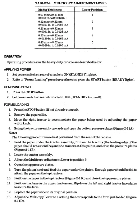
4. Swing the tractor assembly upwards and open the bottom pressure plates (Figure 2-11A).
Note:
The following procedures are best performed from the rear of the console.
5. Feed the paper under the tractor assembly, fit it on the tractors (the leading edge of the paper should not extend beyond the tractors at this point), and close the pressure plates (Figure 2-11B).
6. Lower the tractor assembly.
7. Adjust the Multicopy Adjustment Lever to position 5.
8. Open the top pressure plates.
9. Turn the platen knob and feed the paper under the platen. Enough paper should be fed to attach the paper on the top tractors.
10. Position the paper in the top tractors (Figure 2-11 C) and close the top pressure piates.
11. Position the form on the upper tractors and flip down the left and right tractor face plates to secure the form.
12. Replace the paper slide to its original position.
14. Press the START button.
Note:
If the paper is not properly positioned, the initial loading under the lower tractors may be difficult. If the form does not catch under the tractor properly, begin form loading again with the paper repositioned under the tractors. It may be necessary to apply some pressure to multipart forms as they have a tendency to separate while being introduced.
c
[image:29.621.64.495.138.513.2]B D
Figure 2-11. Paper Loading
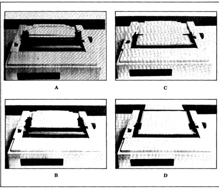
RIBBON CARTRIDGE REPLACEMENT
Ribbons are supplied as operator-replaceable cartridges. The cartridge (M3918-1I4" or
Figure 2-12. Ribbon Cartridge Replacement
The operator replaces the cartridge as necessary to ensure high-quality printing. Cartridge loading includes the following steps:
1. Remove power from the console.
2. Lift off the cover over the print mechanism.
3. Slacken ribbon tension via the ribbon tension knob.
4. Remove worn ribbon cartridge.
5. Slacken ribbon tension on new ribbon cartridge.
6. Position the ribbon between the platen and the print head mechanism. 7. Gently draw the cartridge away from the print mechanism.
8. Carefully position the cartridge on the reference pin and plastic locking clips.
9. Adjust ribbon tension.
10. Replace cover.
11. Apply power to the console.
PRINTTEST
To check print quality and print the entire character set, do the following:
3. Press the TEST button.
4. Press the START button (printing begins).
5. Press the STOP button to terminate the print test.
OPERATOR MAINTENANCE
Operator maintenance includes such preventive maintenance as normal checking and clean-ing performed periodically on a routinely scheduled basis. This maintenance will keep the console in the best operating condition thereby reducing the possibility of downtime.
The following list is a general guide to operator maintenance:
• Always plug the console into a 3-wire grounded outlet.
• Ensure that all covers are closed and secured during operation.
• Never operate the console without paper.
• Avoid leaning on or placing objects on any part of the console.
• Turn power OFF before replacing paper or ribbon cartridge.
• N ever put food or beverage on or near the console. • Keep outside covers clean and free of debris.
• Clean and dust the inside areas of the print mechanism.
DISKETTE UNIT
The single, rackmounted diskette unit is used by the operator solely to load the system offline test and diagnostic (T&D) programs which are recorded on the magnetic oxide coated surface of the Mylar disk (or diskette). The T&D programs for the DATANET are contained on three separate diskettes.
The flexible disk is packaged in an 8-inch-square protective nonremovable jacket. Both diskette and jacket contain a center hole with an access slit that extends from the center to the outer edge. When loaded and operative, the magnetic heads on the diskette unit come into physical contact with the recording surface of the diskette. The jacket becomes immobile and is held stationary while the diskette unit spindle automatically engages the diskette and rotates it at a speed of360 rpm.
CONTROLS
Diskette unit controls include the following:
POWERON/OFF This two-position switch is used to either apply or remove power. In non-tabletop configurations, power is applied from the control panel of the central processor.
Access Cover Button Pressing this button opens the diskette unit access cover to enable either the insertion or removal of the diskette. The access cover is closed manually.
OPERATION
Operating procedures for the diskette units are described below.
APPLYING POWER
Set POWER switch to ON position.
REMOVING POWER
Set POWER switch to OFF position.
Note:
DISKETTE UNIT LOADING
Prior to loading, visually check the condition of the flexible disk. It should not be torn, folded, or creased. Do not use a damaged diskette.
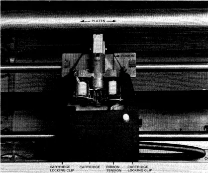
1. Remove the diskette from its protective envelope (Figure 2-13).
Note:
Diskette remains inside its nonremovable jacket.
2. Press the access cover button on the diskette unit.
3. Carefully insert the diskette squarely and completely into the diskette unit.
4. Close the access cover. (The diskette unit spindle automatically engages the diskette and the device is ready for operation.)
PROTECTIVE NONREMOVABLE ENVELOPE JACKET
~\
~
-0
~
-'I"
.. II
[image:32.620.115.545.200.465.2]Jl!!.
Figure 2-13. Diskette Media Handling
DISKETTE UNIT UNLOADING
1. Press the access cover button on the diskette unit.
2. Grasp the diskette jacket and remove it from the diskette unit. 3. Close the access cover ifno other diskette is to be inserted.
4. Return the diskette back into its envelope.
OPERATOR MAINTENANCE
• HOLD HERE
Preventive maintenance includes the checks and cleaning done periodically on a scheduled basis, even though diskette unit operation may be satisfactory and not in need of attention.
CARE AND HANDLING OF DISKETTE
Proper handling and storage of a diskette will increase its life expectancy and reduce the possibility of errors. Observe the following rules for proper media handling and storage.
• Write on labels before adhering them to the nonremovable jacket since writing pressure from a pencil or pen on the jacket may damage the diskette. It is preferable to use felt-tipped pens to minimize contamination.
• Place labels so that they do not obstruct the index sensing hole or adhere the diskette to its jacket.
• It is best not to smoke in the computer room or near the device but, if you must, be extremely careful as smoke and ashes are dirt. Hot ashes are destructive to disks. Food and drink should not be placed on or near the device.
• To reduce the problem of damaged or defective diskettes, never bundle them during storage. Avoid the use of elastic bands or paper clips and store each in its envelope when not in use. Do not stack diskettes on top of other packages.
• Store diskettes in an environment that is the same as the diskette unit operating environ-ment. The recommended environment is from 50°F to 115°F (lO°C to 46°C) with a relative humidity of5% to 90%. Abrupt changes in relative humidity must be avoided.
• Do not expose diskettes to direct sunlight or intense heat.
POWER UP/POWER DOWN/SYSTEM INITIALIZATION PROCEDURES
WrrMLPOWERUPPROCEDURE
Note:
Diskette media should not be inserted in unit until after step 5.
1. Open lower front cabinet door.
2. Set Power Distribution Unit ON/OFF switch to the ON position.
3. Close lower front cabinet door.
4. Insert key into panel security keylock switch and turn key to the maximum clockwise position to unlock the control panel.
5. Set control panel POWER switch to the on position (up). DC ON indicator lights. System is now powered up.
Note:
Power up console next.
COMP~EPOWERDOWNPROCEDURE
1. Power down console and diskette (diskette media should be removed first).
2. Set control panel POWER switch to the off (down) position. DC ON indicator turns off.
3. Open lower front cabinet door.
4. Set Power Distribution Unit ON/OFF switch to the OFF position.
5. Close lower front cabinet door. System is now completely powered down.
NORMAL POWER UP PROCEDURE
Note:
Diskette media should not. be inserted in unit until after step 2.
1. Insert key into panel security keylock switch and turn key to maximum clockwise position to unlock the control panel.
2. &tcontrol panel POWER switch to the on position (up). DC ON indicator lights. System is now powered up.
Note:
NORMAL POWER DOWN PROCEDURE
1. Power down console and diskette (diskette media should be removed first).
2. Set control panel POWER switch to the off (down) position. DC ON indicator turns off. System is now powered down.
SYSTEM INITIALIZATION PROCEDURE
1. Be sure STO P/STEP indicator is lit. If it isn't, press the S (Stop/Step) key.
2. Press CLR (Master Clear) key. This initiates running of QLTs (approximately 10-20 seconds).
Section
3
Fault I solation and Diagnostics
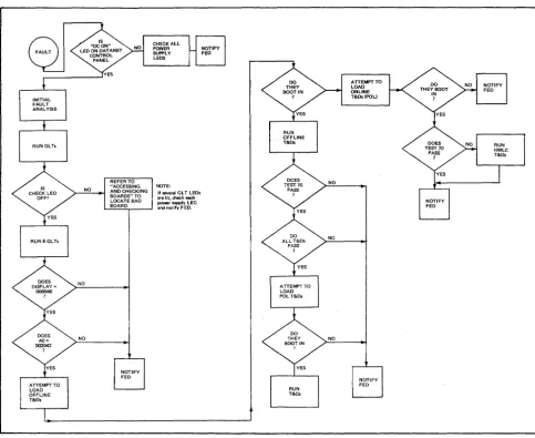
[image:35.617.89.573.176.572.2]This section describes the fault isolation process and the operation of the various test and diagnostics (T&Ds) that an operator must be familiar with. Figure 3-1 shows the proper path to follow.
Figure 3-1. Fault Isolation Overview
INITIAL FAULT ANALYSIS
On the occurrence of any failure, the first step is to determine the resultant state of the subsystem via the DATANEToperator's control panel.
1. Check whether the DC ON LED is lit. If it is lit, proceed to step 2; otherwise open the rear DATANET cabinet door and check the power supply LED indicators (located in the lower right-hand comer). Note which power supply LED indicators are unlit and notify FED. 2. Check that the control panel is operational by displaying and recording the contents of the
following registers:
• Instruction Counter (AD)
• Index Register 2 (A2) • Index Register 3 (A3)
• A-Register (A4) • Q-Register (A5)
• Indicator Register (A6)
3. Check that the elapsed timer is running (refer to ((Check Timer Operation" in Section 2).
4. Display the level zero interrupt location (000400) from the DATANETcontrol panel and take appropriate action:
• If the location = 000000, go to step 5.
• If the location =1= 000000, display and record the channel fault status words in locations
000420-00437. Note:
Status bit interpretation of the channel fault status words is given in AppendixB.
5. Perform a memory dump and have the results, along with the register information from step 2, analyzed by the appropriate personnel.
Note:
Ifmemory parity errors are indicated in the memory dump, the actual memory location of the fault can be determined by selecting register A 7 and pressing Read and Execute. The location displayed will be that of the first memory fault encountered and memory location 000000 will be overwritten with the channel fault status word associated with the fault. This test involves memory only, not the pager or cache. If this test does not indicate a memory parity error, then either it is an intermittent error or one caused by the CPU, pager, or cache.
6. Run Quality Logic Tests next. Note:
If at any time the INT LED indicator remains lit after pressing the Execute button, the CP is either in a ((hung" or non-interruptible ((fault" state. Press the CLR key. Display and record AO and the type of instruction at and before that location.
QUALITY LOGIC TESTS
After the Initial Fault Analysis, the QLTs must be run. The QLTs are firmware-resident test programs residing on all the boards in the DATANET (except memory and DIA). Although the memory and DIA boards do not have QLT functions, they do accept the QLT signal and pass it onto the bus. QLTs are initiated on each board by the receipt of a Master Clear signal from the bus. The Master Clear signal can be initiated from the DATANET operator's control panel via the CLR (Clear) button, from the Host system via the DIA, or from the Power Valid signal sent by the DATANET power supplies to the operator's control panel.
QLTOPERATINGPROCEDURES
QLToperating procedures are as follows:
1. Press CLR (Master Clear) key. The QLT indicators on all applicable boards light and QLTs are running.
Note:
A diskette device with its media inserted and the door closed will reset to track zero, which results in a noticeable click.that indicates the diskette device is powered up. If the diskette door is open, the SSC QLT light may remain on until the second execution ofQLTs.
2. Note that the CHECK LED on the control panel stays lit for the duration of the test (a few seconds).
3. Note that the CP LED extinguishes (if it was lit) and after a few seconds lights and then goes off.
4. Note that the INT LED should not be lit.
5. Note that the register display shows the 18-bit contents of the Instruction Counter (AO); however, the CPU resets the upper three bits of the IC after Master Clear.
6. Refer to the QLT Fault Table (Table 3-1) if the CHECK or CP LED stays lit after a few seconds; otherwise, run the Extended QLTs next.
7. The panel should end up in select, step, and AO.
Control Panel Indication CHECK LED lit CP LED lit (and control panel unusable)
TABLE 3-1. QLT FAULT TABLE
Explanation and Action
Look for board(s) with QLT indicator(s) and/or error light combinations lit. Refer to "Accessing and Checking Boards." Notify FED of results.
Memory may have been destroyed and all. interrupt may have occurred. Parity error may be pointed to by displaying AO. Attempt to Master Clear again and ifunsuccess-ful, power down and up. Consider memory and CP suspect. Run mainframe and memoryT&Ds.
ACCE~/NG
AND CHECKING BOARDS
The operator is required to check and identify malfunctioning boards inside the DATANET Network Processor. The accessing and checking procedures are performed with the power on; therefore, observe the warning note.
WARNING
Do not touch or permit tools to make contact with the logic cards; to do so may cause serious bodily injury. Note also that jewelry, neckties, or other articles of loose clothing should not be worn when performing these procedures.
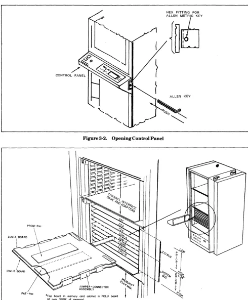
To open the control panel, proceed as follows:
1. Swing open the top and bottom cabinet doors.
2. Locate the release latch assembly on the right-hand side of the system control panel (see Figure 3-2).
3. Insert~ 4-mm Allen key (provided) into hexagonal fittings on latch and press inward. The control panel release latch will disengage and the panel will open.
5. Check the boards in the cabinet for any lit LED indicators. If there are no LED indicators lit, proceed to step 6; otherwise refer to Figures 3-3 and 3-4, and Tables 3-2,3-3, or 3-4 as appropriate. Notify FED which board is defective.
Note:
If several LED indicators are lit, check each power supply LED. Notify FED if any are not lit.
HEX FITTING FOR
ALLE~fEY
ALLEN KEY
}~"
[image:38.620.36.527.107.701.2]/
"
Figure 3-2. Opening Control Panel
PAT-Pac
BF418B Board
(See Table 3-3)
OLT
•
OLT LED
•
CIB Board
Op Code Fetch LED OLT LED
•
•
SSC Board
ROS Parity LED
3
•
QLT LED,
2 1
• •
BH2PRKCache Error Light On = Failure of Cache or Cache is turned off.
CIB/HMLC Error Light ON = OL T Failure SSC Error Lights Either Light On = Failure
=---pa-ri-ty-E-rro-r-LE-o-S--~3 -~2--1--BF410A (See Table 3-3) • • •
BF410B
10M Boards
----~R~O~S-:P~a~rit~v~LE!!':!O~-:O~L~T!"""':"'L~EO~s---BF418A
3 2 1
(See Table 3-2)
•
•
•
BH2PRK- - - -_ _ _ _ _ _ BF418B
CPU Boards
PATU LEOs 10M CP
•
•
OLT LED
---.---~=---BF4PCL (Level 2.1) PATU LEOs
PCLU ROS Parity LED OTL LED 10M CP
• •
- - - - . . - . - - - . - -... - - . . . . - . - - - BF4PCL (Level 2.2)
PCLU Boards
Figure 3-4. QLT and Error LED Locations
TABLE 3-2. CP ERROR LIGHT COMBINATIONS
Definitions
QLT Successful
ROS Parity(PROM board BH2PRK defective) BF418A Board Defective
BF418B Board Defective
CP or Control Panel Failure (cannot determine defective board)
Error Lights
3 2
OFF OFF ON
*
OFF OFF OFF ON OFF ON [image:39.615.118.543.38.354.2]*Indication irrelevant
TABLE 3-3. 10M ERROR LIGHT COMBINATIONS
Error Lights
Definitions 3
QLT Successful OFF
ROS Parity (PROM board BH2PRK defective) ON
BF410A BF4IOA Board Defective
OFF
Board BF4IOB Board Defective OFF
10M Failure (cannot determine defective board) OFF
BF410B Address Parity on I/O Bus *
Board Data Parity Byte 0 on I/O Bus *
Data Parity Byte 1 on I/O Bus ON
*Indication irrelevant
Note:
lOB board LEDs indicate parity errors on memory writes from I/O bus units.