Litho in U.S.A.
3
~Z
COpy NO. ~=-~
_____ __
DATAmoHc 1000
PROGRAMMING MANUAL
VOLUME I
Copyright - 1957
DATAmatic
A Division of Minneapolis-Honeywell Regulator Company 151 Needham Street
Newton Highlands 61, Massachusetts
PREFACE
This manual is intended to serve as textbook and reference for the programmer who will be working with a DATA mat i c 1000 Electronic Data-Processing System. To avoid duplication, attention will be focused upon the system operations, but a basic description of the various units and functioning of the system will be included.
Volume I describes primarily the computational handling of data within the system and defines the various DATA mat i c 1000 instructions available to the programmer. Operation of the Central Processing System is discussed in Section I; the Peripheral Equipment is treated in Sections II - VII.
TABLE OF CONTENTS
INTRODUCTION
Elements of the System ... 0-1 Magnetic Tape Storage ... 0-2 Input Section ... 0-3 Binary Notation ... 0-4
Output Section ... 0-6 Model 1300 ... ,... 0-6 Model 1400 ... 0-6 Integrated Checking ... 0-6 Central Processing Section ... 0-5
SECTION I - CENTRAL PROCESSOR
The DATA mat i c Word ... . Numeric ... . Alphanumeric ... . Instructions ... . Constants ... _.
Registers and Addresses . __ ... _ ... _._ ... _. IZegisters ... _ ... _ Addresses ... .
Sequence Register and Order of Executing Instructions ... _ ... __
Change of Sequence ... . Programming ... .
Classification of Instructions ... _ ... _ .... _ .. _ ... _ ... _.
Arithmetic Instructions ... _ ... . Add (ADD) ... -... . Instruction Modification ... . Flow Diagrams ... _ ... . Speed ... _ ... . Decimal Point .. _ ... _ ... . Subtract (SUB) ... . Multiply (MUL) ... . Decimal Point ... , ... . Rounding Positive Numbers ... . Non-Positive Numbers ... __ Divide (DIV) ... . Decimal Points ... _ ... . Shift ... _ ... . Shift Left Preserving Sign (SLP) ... . Shift Right Preserving Sign (SRP) ... . Shift Left Word (SLW) ... . Shift Right Word (SRW) ... . Substitute (SST) ... _ ... .
Tape and Transfer Instructions ... . Interlocks ... . Read Forward (RFA, RFB, RFD) ... . Read Backward (RBA, RBB, RBD) ... . Read Forward Key Channel (RFK) ... . Read Backward Key Channel (RBK) ... .
1-1 1-1 1-2 1-2 1-2 1-3 1-3 1-3 1-3 1-4 1-5 1-5 1-6 1-6 1-6 1-7 1-8 1-8 1-8 1-10
l-io
1-11 1-11 1-11 1-11 1-12 1-12 1-12 1-12 1-13 1-13 1-15 1-15 1-15 1-18 1-18 1-18Transfer Instructions ... -.. . Transfer In (TIA, TIB, TIS, TID) ... . Sentinels
Weight Count Error ... _. Transfer In Bypassing Interlock
(TBA, TEB, TBS, TBD) ... _ ... . Transfer Internally (TXI) ... . Transfer and Subsequence Call (TXS) ... . Transfer Out (TXO) ... . Write Forward (WFA, WFP) ... _ ... . Rewind Tape (REW) ... . File Maintenance Instructions ... _ ... . Sorting Instructions ... . Switch Tape Half ... " ... . Switch to First Half (SWF) ... . Switch to Second Half (SWS) ... .
Decision Instructions ... _ ... . Numeric Comparisons ... _ ... . Less Than Comparison, Numeric (LCN) ... . Inequality Comparison, Numeric (ICN) .... _. Alphabetic Comparisons ... . Less Than Comparison, Alphabetic (LCA) .. Inequality Comparison, Alphabetic (ICA) ... . Counting ... _ ... _ ... . Tally ... _ ... . Programming and Coding ... _ ... . Marking ... _ ... _ .... _._ ... . Variable Remote Connector ... . The Cyclic Counter ... .
File Maintenance .... , ... -... . Search Instructions ... _ ... . Search Forward Reading (SFR) ... _ ... . Search Forward Writing (SFW) ... . Search Backward Reading (SBR) ... _ .... . Search Backward Writing (SBW) ._ ... _ ... . Key Comparisons ... . First Key Comparison (FKC) ... _ ... . Second Key Comparison (SKC) ... _ ... .
TABLE OF CONTENTS
(Cont·inued)
Sorting Instructions _______________________________________________ _ Double Transfer and Select
(DTA, DTB, DTS, DTD) _________________________ _ Internal Select (ISL) _____________________________________ _ Transfer and Select (TSA, TSB, TSS, TSD) Bypass Interlock (DBA, DBB, DBS, DBD,
BSA, BSB, BSS, BSD) _______________________________ _ Twin Transfer (TTX) __ ~ _______________________ ... .
Control Instructions .. __ .. _ .. __ .. __ .... ____________ .. ____ ._ .. ______ _ Pass (PSS) ... _ ... _. __ ... _ ... _. __ ._._ ... _. __ .... __ ... _. __ . ____ .. _ Sequence Change and Subsequence
Call (SCS) .... _. __ . ___ .. _._._ .. __ .... _ ... __ ... __ . ____ .. __ _ Branch and Return (BAR) ... ___ ... _ .... _ ... _____ .. __ _ Optional Stop (OST) _._._. ____ ... __ . __ .. ___ ... _._. __ . ____ _
Print Instructions . __ . __ . ____ . _____ . ___ .. _____ .... __ . _____ .. _. _______ . Print Numeric (PRN) ___________ . ___________________ . ___ _ Print Alphabetic (PRA) _______________ .. ______________ .
1-32
1-32 1-33 1-33
1-35 1-35
1-35 1-35
1-35 1-35 1-37
1-37 1-37 1-37
Addresses of Significance .. __ . __________ . ___ . ___________________ _ 0000 _________________________ ._. _______________________________________ _ 1981 ________ . ________ . ______________ . ___ ._. __ .. __ ._. ___ . ____ .. __ ._._ ... _ 1982 ... __ ... __ ... __ ... _ ... ____ ... ___ ... __ .. __ ... . 1983 . ___ ... __ ... ___ ... ___ ... __ . ______ . ___ .. _ .. ___ . ______ ._ .. ___ . __ . __ _ 1984 ____ .. ___ ... ________ ... _. ___ .. ___________ . ___ .. ___ . ___ . ____________ _ 1985 ... ___ ... _. ___ ... __ . ___ . ______ ... ___ .. ___ .. ____ . ______________ . 1986 ___ .. ____ ... ___ ... __ .. _______ . ___ ._ .. _. __ . ______ . ____ . _________ _ 1987 __ . ________ ... _._ ... ___ . ____ . ___ ._. __ ... ___ . __ . ___ ._. __________ _ 1988 ___ .. ____ .... _ .. __ ._._._. _________ .... _ .... ____________ . __ .. _______ . 1989 . _______________ ._._. ___ . __ . ________ ._._. ______________ . __ . ________ _ 1990 - Control Register _______________________________ _ 1992 - Output Buffer Register ________ . ____________ _ 1993 - Extractor Register _________ . __ . ______ . ___ .. ____ _ 1994 - Select Instruction Register ________ . ______ _ 1995 - Remainder Register ___ .. ___ . __ . _______________ _ 1997 - Sentinel Register ___ . __ ._ .. ___________ . _________ _ 1999 - Current Instruction Register . __________ .
Summary of Instructions . ___________ . __________________________ _ 1-37 1-38 1-38 1-38 1-38 1-38 1-38 1-38 1-38 1-38 1-38 1-38 1-38 1-38 1-39 1-39 1-39 1-39
1-39
SECTION " -
MODEL 1200 CARD INPUT SYSTEM
Introduction ______ . __ . ____________________ . ___ ._. __________ . __ . ___ ._______ 2-1 Identification and Checking .___________________________________ 2-4
Control Panels __ . ____ ... ______ . ____ . __ . __ ... _ ... _, _____ .________ 2-1 Identification .. __ .. ______________________________________________ 2-4
Card Reader and Card Reading Control PaneL__ 2-2
Checking _______ ._ .. _____________ . __________________________ . ____ .___ 2-6
Application . _____ ._________________________________________________________ 2-7 Conversion Control Panel _ .. __________________ . ______ .... ______ 2-2 Tape Editing ____________________________________________________________ 2-L~
Typical Layout of a DATA mat i c 1000 Electronic Data-Processing System.
INTRODUCTION
The DATA mat i c 1000 is a high-capacity elec-tronic data-processing system designed specifically for application to the increasingly complex problems and procedures required in modern business. The system incorporates significant new systems techniques as well as several basically new component developments. One of the primary features of the DATA mat i c 1000 is its exceptionally large capacity to store information on magnetic tape, coupled with its ability to feed informa-tion from magnetic tape to the processing secinforma-tion and back to magnetic tape at a sustained rate of 60,000 decimal digits per second. In addition, the operational speed of the processing section maintains full compati-bility with this high speed of information transfer.
Two of the most cumbersome aspects of most busi-ness problems are sorting and file maintenance. The DATA mat i c 1000 is equipped with ,an extensive and flexible set of instructions, designed specifically to excel in the performance of these functions and many others. These instructions may be automatically assembled into complete programs by the DATA mat i c ABC-1 Auto-matic Business Compiler. Thereafter, a task which is repeated daily or weekly is initiated simply by reusing the program from its storage on the program magnetic tape.
In the DATA mat i c 1000, reliability is a prime consideration throughout every aspect of engineering and design. The design of electronic circuitry is highly conservative. Every transfer of information within the system is carefully checked to insure that the informa-tion is transferred without alterainforma-tion. In addiinforma-tion, all arithmetic and logical operations are completely checked. All units of the system are constructed of easily replaced standard packages to facilitate maintenance. A system of marginal checking includes circuitry and a special program which may be run periodically to locate any package which should be replaced because of marginal performance. With proper use of this facility, most machine malfunctions will be corrected before they occur.
Elements of the System
The system may be conceived functionally as com-prising three main sections, the Input, Central Processor, and Output Sections, although its physical layout will generally not correspond with such a conception. Data is initially fed into the Input Section in the form of punched cards. This' section, which includes a Card Reader, an Input Converter, and one Magnetic File Unit, reads the data from the cards, translates it into machine language, edits and arranges it into the de-sired format, and records it on magnetic tape.
A High-Speed Memory Amplifier package representative of the modular construction used throughout the DATA mat i c 1000 system.
The Central Processing Section includes (1) Arith-metic and Control Units, (2) the High-Speed magnetic-core Memory, (3) Magnetic File Units, (4) Input and Output temporary storage Buffers, and (5) the Central Console. The Central Processor reads data stored per-manently on magnetic tape, performs all manipulations of data, controls the sequence of functions performed, stores information temporarily while it is being processed and, after processing, stores it permanently on magnetic tape. By means of the Central Console, the operator may monitor the overall operation of the system. As needed, Magnetic File Units may be used by auxillary equipment. Such action is controlled by switches.
The Output. Section converts data from magnetic tape into either punched-card form or printed form, performing considerable editing in the process. The Model 1300 Output Converter, which feeds standard punching and/or printing equipment, may either replace or supplement the Model 1400 Output Printing System, depending on the quantitative requirements of the sys-tem for output information. One Magnetic File Unit . may be considered a part of the Output Section.
Magnetic Tape Storage
The basic medium for the storage of information in the DATA mat i c 1000 is magnetic tape. The particular tape used, the method of recording informa-tion on it, and the tape-handling equipment have all
0-2
been designed or selected to be mutually compatible and to provide high capacity, ease and speed of access to information, ultra-reliable storage and recovery of information, and maximum utilization 'of space on the tape.
Type VTR-179 magnetic tape has been selected for the DATA mat i c 1000 because of its reliability and long life. This tape consists of a layer of iron oxide bonded to a tough, durable Mylar plastic base. A reel of tape is three inches wide and 2700 feet long and can store over 37,000,000 decimal digits of information, the equivalent of data which would require 465,000 punched cards.
Stored information is recorded on the magnetic tape in groups of magnetized spots. The length rather than the strength of these spots is used to form a dot-dash code representing the encoded digits, letters, and symbols. This, the first of a series of unique reliability features, assures that variations in the recorded signal strength will not result in errors .
INTRODUCTION
DATAmatic 1000 Magnetic File Units
block while the tape travels in one direction and in the blocks omitted while the tape travels in the reverse di-rection. The blocks not filled in a given direction of travel provide the space for starting and stopping the tape in that direction. As a result, information is re-corded on almost the entire area of the tape. Moreover, since the reversal of tape direction is accomplished automatically, all of this information is written or read sequentially and the tape is positioned at its physical beginning at the conclusion of this process.
Information is recorded lengthwise to the tape in 31 channels, a system which greatly speeds the transfer of information and facilitates searching processes. Specif-ically, as many as ten tapes may be searched simultan-eously, which means that the system is actually passing over 600,000 decimal digits per second while seeking the particular item desired. The read-record head will write on the tape at the sustained rate of 60,000 decimal digits per second and will recover this information at the same rate. The reading or searching operations may be performed with the tape travelling either forward or backwaFl.
The tape-drive mechanism and the read-record head are contained in the Magnetic File Unit. An
in-stallation may include from four to one hundred Mag-netic File Units, all directly connected into the system. They may be divided in any manner and at any time between the reading and recording operations. The volume of transactions and the complexity of operations govern the number of Magnetic File Units required for a given system. Furthermore, these units may be added to or removed from the system at any time as these requirements vary.
In order that any Magnetic File Unit may be in-terrogated and information recovered from it without interrupting the operation of the Central Processor, a File Reference Unit is available. Thus a Magnetic File Unit may, at different times, be recording data received from the Input Converter, reading data to the Output Converter, recording data from the Central Processor, reading data to the Central Processor, or reading data to a File Reference Unit. Also available is a File Switching Unit which increases the flexibility with which Magnetic File Units may be arranged into the various functional groups.
Input Section
Data enters the DATA mat i c 1000 on standard 80-column punched cards which are initially read by
INTRODUCTION
the Card Reader. In this unit the card is read twice, the two readings are compared, and the card is stacked. The input system will produce a signal to indicate any card whose two readings are not identical. The Card Reader holds batches of over 3000 cards at one time and passes them at the rate of 900 fully punched cards per minute.
The information which is read from the punched cards is translated into the language of the system and arranged in the format of the magnetic tape by the Input Converter. In this process, it passes through two control panels and two temporary storage locations, providing great flexibility for transposition, duplication, and discarding of information. The operator manually sets an identifying control number into the Input Con-verter, which includes this number in the information to be written on magnetic tape. The control number may then be written on the batch of cards which' it represents, in case it is desired later to cross-reference these cards with their corresponding tape.
The encoded information is first arranged in a 100-column format within the converter. In this conversion any number of card columns may be duplicated
pro~
vided that the total number of columns does not exceed 100. Triplication of columns is not permitted. Thirteen conversion rules are available for the translation of punch code into machine code. Any single card column may be translated by anyone of these thirteen rules. The information is then translated into the final tape format, the contents of two punched cards being fed to each block on the magnetic tape. Several automatic checking features are built in to detect improperly punched cards or errors either in reading or in one of the conversion steps. The operator controls the settingsof a group of panel switches which direct the course of action that the machine is to follow in each of these situations.
It must be emphasized that the operation of the Input Converter is strictly "off-line". That is, it pro-ceeds entirely independently of and simultaneously with the data-processing and/or output functions. Normally, one or more specific Magnetic File Units are assigned the function of writing on tape all raw data received from input and communicating it to the Central Pro-cessor.
Binary Notation
Information which is manipulated, stored, or com-municated other than by electronic systems is generally written using 10 decimal digits, 26 alphabetic characters, and a number of punctuation marks and other special symbols. Basic to the adaptation of information to elec-tronic systems is the fact that such information can be written entirely in terms of two symbols, generally called zero and one. This presentation is called binary notation and is analogous to the presentation of information in the more familiar Morse code, in which the two symbols used are called dots and dashes. The symbols used in a binary notation are called binary digits or bits. For example, the ten familiar decimal digits, 0 through 9, are represented in binary notation as follows:
5550
00161
56561
10116
66516
26111
76611
31500
86166
41561
9Bars will be placed over binary digits to distinguish them from decimal zeros and ones.
OAT A mot i c 1000 Central Processor Section
The storage of information by electronic equipment depends upon the ability to distinguish between two states which represent the two symbols used in binary codes. There are many electronic devices which can make such a distinction. An example of such a device which is both fast and reliable is the tiny, ring-shaped magnetic core. This core may be magnetized in either of two senses; in one sense it is considered to be storing a binary zero and in the other sense a binary one. These tiny magnetic cores constitute the principal element for the storage of information in the High-Speed Memory and buffer storage units of the DATA mat i c 1000 Central Processor. In a group of four such magnetic cores, ten of the sixteen possible combinations of states may be used to represent the ten decimal digits.
Central Processing Section
The Central Processor has already been defined to include the Arithmetic and Control Units, the Input and Output Buffer Storage Units, the High-Speed Memory, the Magnetic File Units, and the Central Console. Together, these units contain the electronic elements and circuitry for high-speed performance of the stored programs.
The fast and reliable internal memory is composed of over 100,000 magnetic cores and has a capacity of 24,000 decimal digits. Access is in parallel for rapid readout of stored information. Processing of data stored on magnetic tape is also enhanced by the inclusion of two Input and two Output Buffer Storage Units. These buffers, which are each capable of storing 744 decimal digits, permit a steady flow of information to and from memory and enable the memory to read from one tape and write on another simultaneously.
INTRODUCTION
The design of the Central Processor and the pro-vision of certain special instructions are specifically aimed at the attainment of high sorting, merging, and file-maintenance speeds. Some examples of the speeds achieved are:
Sort - 60,000 decimal digits per second (equiva-lent to 750 fully punched cards per second). Merge - 60,000 decimal digits per second. File Maintenance - 600,000 decimal digits per
second.
Arithmetic instructions are carried out by the Arithmetic Unit. The sequence of performance of the stored instructions is directed by the Control Unit. The Central Console is the means of human communi-cation with, and control over, the system. It affords active human control over starting and stopping the machine and passive communication in displaying a continuous picture of the status of the DATA mat i c 1000 as it processes a program instruction by instruction. The latter property is an exceptionally useful diagnostic tool for program debugging. The Central Console also mounts a special automatic typewriter which is used for the manual insertion of data to the machine and for the interrogation of the machine. The components of the system can be checked out by running the marginal check program. The Console displays the results which indicate whether any package in the system is approach-ing an unsatisfactory level.
A fundamental reliability feature of the system is the fact that each basic unit of information includes a check digit called the weight count. This weight count is recomputed after each transfer of information within the Central Processor. The arithmetic comparison of
DATA mat i c 1000 Central Console showing simplicity of layout achieved through functional design
INTRODUCTION
the original and the recomputed weight counts is an extremely positive and economical means of verifying all internal information transfers, plus arithmetic and logical operations.
Output Section
The Output Section, like the Input Section of the DATAmatic 1000, operates entirely "off-line". It accomplishes the conversion of information stored on magnetic tape into the form of punched cards or printed copy. Two alternative output sections are available which may be purchased either singly or to-gether, depending on the quantity and speed require-ments of the application. These are the Model 1300 Output Converter, which provides the required output to drive a standard card punch and/or a standard 150-line-a-minute printer, and the Model 1400 Output Printing System which includes a special DATA mat i c High-Speed Printer capable of printing 900 lines per minute. As is the case in the Input Section, one or more Magnetic File Units are normally assigned to communicate between the Central Processor and the Output Converter.
MODEL 1300: The Model 1300 Output Converter re-duces data stored on magnetic tape to a form accept-able to a standard 150-line-per-minute tabulator and/or a standard 100-card-per-minute card punch. The tabu-lator and card punch functions, governed by standard control panels, are preserved.
Information is read from magnetic tape to the converter in quantities of up to 192 decimal digits, 128 alphabetic characters, or equivalent. Each of these sets of data is processed individually and becomes the basis of one line of printed output and/or one 80-column punched card.
The data is then read into converter output storage through a code translator, controlled by a conversion control panel. There are 14 rules for the translation of machine language into standard punch-card codes.
The output storage section simulates 120 columns of punch-card data, in which form the information leaves the converter. Format arrangement and all other standard printout functions are governed in normal fashion by the control panels associated with the readout equipment. In the case of the card punch, the data is converted into the standard 80-column format and transposition and duplication of columns are effected, as desired, by proper wiring of the card punch control panel.
MODEL 1400: The Model 1400 Output Printing System operates from a completely flexible tape format and performs a considerable amount of editing and format arrangement while preparing information to be printed at the rate of nine hundred 120-character lines per minute. In fact, the most complicated printed formats are obtained with a minimum amount of pre-editing required in the Central Processor. Special symbols and legend material can be emitted. Also the printing of certain parts of the form may be suppressed, dependent
0-6
upon the content of other data within the particular record. Furthermore, the same output tape may be used for several differept types of printing runs by wiring and using all of the control panels in the equip-ment. The sequence of information on magnetic tape need not have any relation to the sequence of printing of information within a given line. It is, moreover, possible to scan a record on the tape several times, on each occasion deriving diffel'ent combinations of data to be printed on a given form; data from the tape may be rejected or printed severa 1 times at will.
From the moment that information is read from the magnetic tape to the actual printing process, a complete train of information monitoring exists to pre-clude the possibility of printing erroneous information. This system includes a read-back signal from the actual printing hammer to the original stored information to verify the correctness of the character being printed in every column of the form.
The High-Speed Output Converter reads informa-tion from magnetic tape in discrete quantities of up to 192 decimal digits. These quantities may be read from any part of the block and are handled as separate units of information throughout the conversion process. Three control panels are used to select the input in-formation, translate it into the language of the High-Speed Printer, edit and position it, and store it in the 120-position print storage. There are 160 printing posi-tions available on the High-Speed Printer, of which any 120 may be used during a given run. Two addi-tional control panels are used to select the particular 120 print positions to be used and to perform further editing.
Integrated Checking
SECTION I
SECTION I - CENTRAL PROCESSOR
THE DATAmatic WORD
The fundamental parcel of information which the DATA mat i c 1000 can manipulate is called a word. It is an assemblage of 52 bits which can have different interpretations depending upon the use of the word in the DATA mat i c 1000. The three basic types of words are numeric, alphanumeric, and instruction, each of which has a prescribed bit structure. Moreover, the bits of a word may be arbitrarily grouped to serve a specific function.
NUMERIC: In a numeric word, the 52 bits are grouped into thirteen 4-bit sets called digits. The leftmost digit contains a code which represents the sign of the number; 1101 equals plus (+) and 0101 equals minus (-). The rightmost digit performs a special checking func-tion, to be described shortly. The eleven remaining digits are interpreted as eleven decimal digits. Thus the number
+
78901234567is represented in the system as shown in Figure 1-1.
In order to perform most arithmetic operations on numeric words in the system, it is necessary that these words be signed as indicated above. Frequently, a numeric word contains reference information only and is not normally included in arithmetic operations. Under these conditions, the leftmost digit does not have to, be a sign and can contain another decimal digit. W or-ds of this type are called unsigned numeric, as distinguished from the more common signed numeric words.
A group of four bits can have 16 distinct configura-tions, and therefore can be used as a code having 16 different values. When a group of four bits has one of 16 different values, it is called a hexadecimal digit. (The term hexadecimal is frequently abbreviated as hex.) Numeric words are interpreted as eleven (signed) or twelve (unsigned) digits where each digit is represented by four bits. Therefore, a numeric word could also specify eleven (signed) or twelve (unsigned) hexadeci-mal digits. The external symbols which are used to express hexadecimal digits include the normal decimal digits plus an arbitrary selection of values to represent
Bit Position 52 51 50 49 48 47 46 45 44 43 42 41 Binary Digit
i i
0
i
0
i
I
I
I
0 0 0
Bit Position 28 27 26 25 24 23 22 21 20 19 18 17 Binary Digit 00
1
0
0
0
i I
0
i
0
0
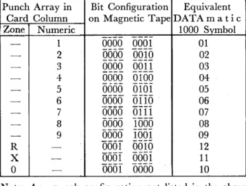
the hex numbers between 10 and 15. The complete table of hexadecimal codes is given in Table 1-1.
The rightmost four bits are called the Weight Count and represent a decimal digit used to check the correctness of the rest of the word. It is computed by adding the numeric values of the first twelve
hexa-Special Numeric E
Bit Code Normal Symbols Value
0000
0 0 00001
1 1 10010
2 2 2oOli
3 3 3oioo
4 4 40101
5 5 5ariD
6 6 6oiii
7 7 7iooo
8 8 8Iooi
9 9 91010
B$
@
ioil
C@
lioo
D@
litH
E +@
iiio
F (space)0
il11
G*
@
e
The circle is p lac e d around 10 in this column in order to stress the fact that@
corresponds to the four bits,UHo,
rather than the eight bits0001 0000.
Similarly for@ ,
etc.Table 1-1
40 39 38 37 36 35 34 33 32 31 30 29
I
0 0
I
0 0
0
0
0 0 0
1
16 15 14 13 12 11 10 9 876 5 4 3 2 1
o
i
o
1
0
1
I
0
a I I I
XXXX
Figure 1-1
SECTION I - CENTRAL PROCESSOR
THE DATA mat i c WORD
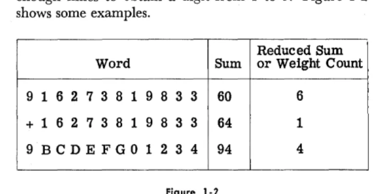
decimal digits and reducing the sum by subtracting enough nines to obtain a digit from 1 to 9. Figure 1-2 shows some examples.
Reduced Sum Word Sum or Weight Count
9 1 6 2 7 3 8 1 983 3 60 6
+ 1 6 2 738 1 983 3 64 1
9BCDEFG01234 94 4
Figure 1-2
In the case where ·the first twelve hexadecimal digits are all zeros, the weight count will be nine. It is important to note that every word, numeric, alpha-numeric, or instruction, is treated as numeric for the computation of its weight count. The weight count is computed by the Input Converter and attached to the word before recording on magnetic tape. There is no requirement for the manual computation of weight count. Whenever the word is moved from one part of the system to another, the weight count is recomputed and checked. As soon as an incorrect weight count is detected, the machine will stop immediately to permit corrective action.
ALPHANUMERIC: In an alphanumeric word the 52 bits are grouped into eight 6-bit groups and one 4-bit group. The 4-bit group comprises the four rightmost bits and, as in the case of the numeric word, is used to specify the weight count of the word. The eight 6-bit groups are called characters and contain codes which are in-terpreted as alphanumeric characters by the associated DATA mat i c 1000 equipment. There are 64 possible configurations of the six bits in a code. All 64 configura-tions and the corresponding alphanumeric symbols are listed in Table 1-2.
The codes which are specified as unassigned have no interpretation. However, these unassigned codes should not be substituted for space codes in output data because they may stop the operation of the peripheral equipment. As an example of alphanumeric binary coding, the name John H. Smithers would be stored internally as shown in Figure 1-3.
INSTRUCTIONS: Words can be interpreted as instruc-tions by the system, in which case the word directs the machine to perform a certain operation involving other words to be found at specified locations. Two hexa-decimal digits are used to specify the internal operation which is to be performed. The rightmost four-bit group, as in all words, specifies the weight count of the word. The remaining digits are used to specify the location 6f words or to specify numbers required to perform the· instruction. Prior to any further discussion of the interpretation of a word as an instruction, it is necessary to define registers and addresses.
CONSTANTS: A DATA mat i'c word whose contents
1-2
000000 0 (Zero)
oooooI
1ooooIo
2oOOOII
3oooIoo
4OOOIOI
5OOoIIo
6OOoIII
7OOIOOO
8OOIOOI
9OOHHo'
{JOIOII
#OOIIOO@
ooIIoI
+OOIIIo
(Unassigned)001111
(Unassigned)010000
(Space)oIoooI
AoIooIo
BOIoOII
C010100
DoiOIOI
EOIOIIo
FOIoIII
G{JIIOOa
HOIIooI
IOIIOIo
Cr.OIIoII .
(Decimal Point or Period)oIIIoo D
a IIIol (
OllIla)
alII II
(l!nassigned)Iooooo -
(HYPhen-:lMinus)vJ.
I
IooooI
JIoooIo K
IOOOII,L
Iaoloo
MIooIoI
N100110
0 (letter)100111
PIoIooo Q
IoIoOI
RIoIoIo
=IoIoII
$101100
*
101101
~I.oIIIO
(Unassigned)IoIIII
(Unassigned)IIoooo
&IIOOOI/
IIooIo
SIIooII
TIIoIoo U
IIoIoI
VIloIlo W
IIoIII
XIIIoOO Y
IIIooI
ZIIIoIo :
IIIoII ,
IIIIoo
%
IIIIoI
1/2IIIIIo
(Unassigned)IIIIII
(Unassigned)Table 1-2. Alphanumeric Binary Code
SECTION I - CENTRAL PROCESSOR
REGISTERS AND ADDRESSES
Alphanumeric Code
Alphanumeric Symbol
IooooI IooIIo oIIooo IooIoI oIoooo oIIooo oIIoII oIoooo
J 0 H N (space) H (space)XXXX
Alphanumeric CodeAlphanumeric Symbol
II06Io IooIoo oIYooI IIooII oIIooo oIoIoI IoIooI IIooIo
S M I T H E R Sxxxx
Figure 1-3
REGISTERS AND ADDRESSES
REGISTERS: The DATA mat i c 1000 word requires a set of 52 elementary storage devices. Such a set of storage devices is called a register. In the process of executing. a typical instruction, information is taken from selected registers, manipulated, and stored in other registers. In order to select the proper words for each instruction, each register in the High-Speed Memory must have a unique identification, called an address. The internal High-Speed Memory consists of two banks of 1000 registers each, designated as bank
a
and bank 1. ADDRESSES: Within each bank, the registers are as-signed decimal numbers from 000 to 999, called sub-addresses .. An address consists of a bank designator,0
orI,
followed by a subaddress. For example, 1100 is the address of the word in register 100 of bank 1. Note that the bank designator is specified by a single bit, so that the complete address requires only 13 bits in an instruction.Registers between 1990 and 1999 have special uses and are called special function registers. Of this group
Bits
52
51-49
48-41
40-29
of registers, 1991, 1996, and 1998 do not exist. Special use is also made of registers 1981 to 1989. A bar has been placed over the first digit of each address to re-mind the reader that this digit represents one bit rather than four. When there is no danger of confusion, this bar will be omitted.
When a word is specified as an instruction, it has the format shown in Figure 1-4. The hexadecimal code which selects the internal operations is specified in bit positions 48 to 41. The A address is composed of the bank designator, bit 51, and the subaddress, bits 40 to 29. Similarly, the B address comprises Bits 50 and 28 to 17 and the C address bits 49 and 16 to 5. The space in an instruction which is usually reserved for an address is sometimes used for other purposes. Examples will be discussed in the detailed discussion of the DATA mat i c 1000 instructions. Bit 52 is interpreted as the sign of an instruction and is used when an instruction is to be modified by addition or subtraction.
28-17
16-5
4-1
Function Sign ABC Operation Code ASubaddress B Subaddress C Subaddress Weight Count
.A.
( bank designators Figure 1-4
SEQUENCE REGISTER AND ORDER OF EXECUTING INSTRUCTIONS
Before proceeding to describe all the instructions in detail, it is important to know how an instruction is executed and how the Central Processor knows which instructions to perform and in what sequence. There are two registers which are important in this regard. One is the Control Register (1990); the other is a special register (containing one address) which is called the Sequence Register. We start with the instruction to be performed in the Col1trol Register. The process of executing the instruction includes:
(1) analyzing it to :determine its type (2) performing it
(3) selecting the next instruction and placing it in the Control Register.
In regard to the last step, instructions fall into two classes: "normal" instructions and "subsequence call"
instructions. For a normal instruction, step (3) consist!j of putting into the Control Register the instruction whose address is in the Sequence Register and then adding "one" to the address in the Sequence Register. Thus a succession of normal instructions would be per-formed from consecutive registers. For a subsequence call instruction, step (3) consists of putting the instruc-tion in the C address into the Control Register, ignoring the Sequence Register completely. Thus, a series of sub-seq\l.ence call instructions can be taken from a set
or
randomly chosen registers in the internal memory and the address in the Sequence Register is left unmodified during the execution of these subsequence call instruc-tions .. The execution of any normal instruction auto-matically leads to the use of the Sequence Register for the selection of· the next instruction. The ability toSECTION J - CENTRAL PROCESSOR
SEQUENCE REGISTER AND ORDER OF EXECUTING INSTRUCTIONS
DsDaDbDc Operation Code A Subaddress B Subaddress C Subaddress Weight Count
i 0
0 0
0000 0000
0000 0000 0000
0000 0001 0001 0000 0010 0000
XXXXFigure t-5
perform a sequence of instructions in the subsequence mode and then to return to the main thread of pro-gramming via the Sequence Register without any addi-tional instructions required to direct this operation is a unique feature of the DATA mat i c 1000. In some cases, it leads to a significant reduction in the number of instructions and to considerable increase in speed.
CHANGE OF SEQUENCE: The function of certain instruc-tions is to change the contents of the Sequence Register. Such instructions make it possible to perform instructions in any sequence desired by the programmer who pre-pares the program. Thus, in summary, normal instruc-tions are performed in sequence unless one of them changes the contents of the Sequence Register in some fashion other than to add "one" to it. Subsequence call instructions are performed in the sequence determined by the C address of the instruction. The subsequence call instructions will be defined as each instruction is discussed. The normal instructions are all other in-structions plus subsequence call inin-structions whose C address is zero. Certain instructions (e.g. ADD) result in a subsequence call to a special address under certain circumstances. These will be described in detail later.
At this point it would be well to define the Sequence Change and Subsequence Call instruction to illustrate the above remarks about the sequence of performing instructions. This instruction is designated SC2.~:..! t~.9p~r
ation code is 00 (appearing in bits 48-41 as 0000 0000). The A address is not used in this instruction. Prior to step (3), the B address is put in the Sequence Register unless it is zero, in which case it is ignored. If C is not zero, the instruction is a subsequence call and C is the address of the next instruction. If C is zero, the instruc-tion is normal and the Sequence Register contains the address of the next instruction. For example, in the instruction shown in Figure 1-5, the A address is
o
00050050 0550
or 0000, which is written as O. The B address is0 0505 005T 555T
or 0011, which is written as 11. The C address isa m)Qo
0010 0050
or 0020, which is written as 20. The operation code indicates that the .. instruction is SCS. The instruction can then be written in hexadecimal form:DsDaDbDc Operation A Sub- B Sub- C Sub-Code address address address
8 00 000 011- 020
It is simpler yet to write it~ SCS/0/11/20 This is a shorthand notation to indicate the type of
1-4
instruction and its addresses which are SCS, 0, 11, and 20, respectively. After a few more examples, this kind of notation will be used consistently without referring to the binary form of the word. The instruction SCS/0/11/20 causes the Central Processor to put 11
(the B address) into the Sequence Register and then to get its next instruction from register 20 (the C ad-dress) .
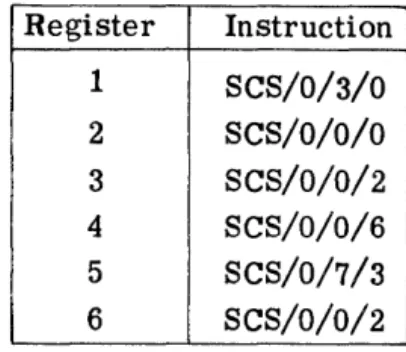
Figure 1-6 illustrates the sequence of performing a series of SCS instructions. S. R. stands for the Sequence Register and C. R. for the Control Register .. It is as-sumed that initially zero is in the Control Register, one is in the Sequence Register, and registers 1 through 6 contain the following instructions:
Register Instruction
1 SCS/0/3/0
2 SCS/O/O/O
3 SCS/O/0/2
4 SCS/O/O/6
5 SCS/O/7/3 6 SCS/O/0/2
First instruction, SCS/O/O/O: The instruction is recognized to be type SCS in step 1. In step 2, the Sequence Register is not altered since the B address of the instruction is zero. In step 3, since this instruction is normal (its C address is zero), the next instruction is selected from register 1 (the address in the Sequence Register) and one is added to the address in the Se-quence Register.
Second instruction, SCS /0 /3/0: In step 1, the instruction is recognized to be type SCS. In step 2, B is put into the Sequenee Register since B is not zero. In step 3, since this instruction is normal, the next instruction is selected from register 3 (the address in the Sequence Register) and one is added to the address in the Sequence Register.
A Set up
SECTION I - CENTRAL PROCESSOR
CLASSIFICATION OF INSTRUCTIONS
Put next instruction Make final adjustment to d Current Contents of Sequence Register in Control Register Sequence Register d Instruction Sequence
r ,in Control Register If B
F
0, If B = 0, If C 1= 0, IfC = 0, If current If current Instruction e Register at start put B in let S. R. put con- put con- instruction instructions at start S. R. stand tents of tents of is normal, is a
subse-s C in C.R. S.R. add- Add 1 to quence call,
ress in C. R. S. R. let S. R. stand. 1
9
First 9 SCS/O/O/O 1 1 SCS/0/3/0 2
0
Second 1 SCS/0/3/0 2 3 SCS/0/0/2 4
Third 3 SCS/0/0/2 4 4 SCS/O/O/O 4
Fourth 2 SCS/O/O/O 4 4 SCS/0/0/6 5
Fifth 4 SCS/0/0/6 5 5 SCS/0/O/2 5
Sixth 6 SCS/0/0/2 5 5 SCS/O/O/O 5
Seventh 2 SCS/O/O/O 5 5 SCS/0/7/3 6
Eighth 5 SCS/0/7/3 6 7 SCS/0/O/2 7
Ninth 3 SCS/0/0/2 7 7 SCS/O/O/O 7
Tenth 2 SCS/O/O/O 7 7 Instruction 8
from 7 Eleventh 7 Instruction 8
from 7
Figure 1-6
PROGRAMMING: The process that the programmer goes through to prepare a problem for solution consists of writing the necessary instructions to execute, step by step, the operations required. These instructions are then placed in the internal memory and the DATA mat i c 1000 proceeds to execute the instructions in the sequence specified by the programmer. In order to do this work successfully, the programmer must be well aware of the distinction between normal instructions and subsequence call instructions. The use of normal and subsequence call instructions is illustrated further in a later section. At this point, it is worth considering how a word is distinguished as an instruction, a number, or an alpha-numeric. The operator determines which instruction will be first when he starts the system. After the com-puter has started, each instruction, in conjunction with the Sequence Register, determines which instruction
will be next. Thus, one by one, the words which are to be interpreted as instructions are brought into the Control Register, analyzed, and executed. If by mistake the programmer (or machine) has put a number or a name into a register where an instruction should be, the system will put this number or name into the Control Register. The system may discover that the word cannot be an instruction and halt with an error indication. It is conceivable that a number could be interpreted as a legitimate instruction, but the programmer takes pre-caution to avoid this situation. In preparing a problem, he also needs certain numbers which are placed in the memory at desired locations by a series of appropriate instructions. The process of determining the appropriate instructions is called programming. In brief, then, it is the programmer who determines which words are instructions, numbers, or alphanumerics.
CLASSIFICATION OF INSTRUCTIONS
The instructions may be conveniently classified into six functional groups: Arithmetic Instructions, Tape and Transfer Instructions, Decision Instructions, Sorting Instructions, Control Instructions, and Print Instruc-tions. In the detailed discussion of these groups, it must be realized that the address of a register is, of course,
not the same as the word in the register. In order to avoid the confusion which sometimes arises, the symbol (A) will be used when referring to the word in the register at address A. This symbol represents the con-tents of A or the word in A.
SECTION I - CENTRAL PROCESSOR
ARITHMETIC INSTRUCTIONS
ARITHMETIC INSTRUCTIONS
ADD: Add is typical of the arithmetic instructions. Its operation code is FF or
III5 T110.
This instruction is written ADD/ A/B/C and it is read: "Add (A) to (B) and put the answer in C." That is, add the number in A to the number in B and store the sum in C. Ifthe sum of the numbers at A and B is too large to store in a single register, there is said to be an overflow. In this case, the high-order digit of the sum is lost and there is an automatic subsequence call to 1988, the Accumulator Overflow Register. The programmer will presumably have stored in 1988 the first instruction of a special action to take care of this situation. The Add instruction does not disturb the words at A and B. In fact, it is a general rule that the machine does not alter the contents of a register just to use them.
Previously, it was noted that any string of
48
bits with four extra check bits is called a word and that groups of four of these bits can be used to represent decimal digits betweena
and 9 inclusive. It was also noted that a group of four bits may also represent six other hexadecimal quantities which have been arbitrarily designated as B, C, D, E, F, and G. These obviously are not decimal digits. The arithmetic instructions were designed basically to perform decimal arithmetic. This means that they will perform proper arithmetic opera-tions on decimal numbers with valid signs(llof
for plus and5f51
for minus) in digit positions 52 through 49. It has further been noted that certain words in the machine, instructions in particular, will contain hexa-decimal digits which are not proper hexa-decimal digits. Unless he wishes to modify an instruction, the user will not normally attempt to add two words which are not honest decimal numbers. If he does attempt to add two words which are not legitimate decimalnum-bers, the machine may stop and indicate an error. INSTRUCTION MODIFICATION: Instructions usually have illegitimate signs since the first four bits are sign bit and bank designators and could be any hexadecimal char-acter. The two characters of the operation code can be hexadecimal digits. Furthermore, the subaddress posi-tions of certain instrucposi-tions can contain non-decimal characters. Since the D A TAm a tic 1000 is basically a decimal machine with decimal arithmetic, it has been necessary to make special provision for modifying in-structions by addition and subtraction and these special provisions include certain restrictions which the pro-grammer must understand.
( 1) The instruction must be in address A and the number to be added in address B; other-wise the machine may stop.
(2) If a hexadecimal digit in the word at address A is added to any digit, decimal or hexa-decimal, from the word at address B, the sum must not exceed hex G; otherwise the machine will stop.
(3) Addresses greater than 999 cannot be ob-tained (because of the position of the bank designator) by adding to addresses less than
1000.
With these three restrictions in mind, the programmer will have no difficulty modifying instructions as desired. EXAMPLE: As an example of the use of the Add instruc-tion, assume that in registers 1 through 8 the words shown in Figure 1-7 (in binary form) have been placed. When it does not matter what is in certain words, a dash instead of
a:
digit is used. Ds is the sign bit for instruc-tions. Da , Db, and Dc are the bank designators foraddresses A, B, and C, respectively. The first three
R CONTENTS OF REGISTER
e
Dsn
g
Weight·
i a
l1n
Instruction A Subaddress B Subaddress C Subaddresss Type Count
t c
e
r 52-49 48-41 40-29 28-17 16-5 4 -1
1 TTUT UUUU UUUU UUUU UUUU UUUU UUUU UUUU UUUU UUUU UUUT UUTU
----2 TTUT UUUU UUUU UUUU UUUU UUUU UUUU UUUU UUUU UUUU UUUU TUUT
---3 UTUT UUUU UUUU UUUU UUUU UUUU UUUU UUUU UUUU UUUU UUTIT UUTT
----4
----
----
----
----
----
---- ---- ---- ----
----
----
----
----5
----
----
----
---- ---- ----
---- ----
----
----
----
----
----6 TUUU TTTU T1TU UUUU UUUU UUUl: UUUU UUUU UUTU UUUU UUUU UTUU
----7 TUUU TTTU T1l:U UUUU UUUU UUUl: UUUU UUUU UUTT UUUU UUUU UTUT
----8 TUUU TTTU TTTU UUUU UUUU UTUU UUUU UUUU UTUl: UUUU UUUU UTUT
.-SECTION I - CENTRAL PROCESSOR
ARITHMETIC INSTRUCTIONS
Register Contents of Register
*
Instruction A Sub- B Sub- CSub-Type address address address
1 + 00 000 000 012
2 + 0.0 000 000 009
3
-
o
0 000 000 0134
-
-
-
-
- -
-
- -
-
-
-5
-
-
-
-
-
-
-
-
--
-
-6 8
FF
001 002 0047 8
FF
00 1 003o
0 58 8
FF
004 005 005*
This column represents the sign if the word is a number and it represents the sign bit and bank designators if the word is an instruction. It represents unspecified bits in words 4 and 5 .Figure 1-8
words are numbers and therefore their bits 52-49 are signs; the last three words are instructions which manip-ulate these numbers. The headings Ds , Da , Db, Dc, Instruction Type, etc., refer only to the instructions.
These instructions are shown in the more compact hexadecimal form in Figure 1-8. Even more compactly,
+
12 could be written as a shorthand notation for the word in register 1. Furthermore, as mentioned above it will be convenient and helpful to the reader's memory to write ADD instead of FF and 1 instead of 0001 for the A address of the instruction in register 6, etc. Thus Figure 1-8 could be further condensed to the form of Figure 1-9.If 6 (i.e. 0006) is put in the Sequence Register and the computer is started, it will execute the instruc-tions in registers 6, 7, and 8 successively, and then go on to whatever instruction is contained in register 9. As a result of performing the instruction in register 6,
+
12+
9=
+
21 will be sent to register 4, replacing whatever may have been there. The contents of registers 1 and 2 are not affected by this instruction. Similarly, the result of the next instruction in register 7 is to putRegister Contents
1 +12
2 +9
3 -13
4
----5
----6 ADD/l/2/4
7 ADD/l/3/5
8 ADD/4/5/5
Figure 1-9
+
12+ (
-13) = -1 in register 5 and the result of the instruction in register 8 is to put+
21+ (-
1) =+
20 in register 5, replacing the - 1 which was there temporarily. Thus these three instructions may be summarized as shown in Figure 1-10.FLOW DIAGRAMS: It is useful, especially in more com-plicated situations, to summarize the effect of the
in-Register
Instruction (SymboliC Form)
Effect of Instruction
.,
6
ADD/l/2/4
(1)
+
(2)
=
+21~47
ADD/1/3/5
(1) + (3)
=
-1---.5
8
ADD/4/5/5
(4) + (5)
=
+20---5
SECTION I - CENTRAL PROCESSOR ARITHMETIC INSTRUCTIONS
structions still more compactly by means of a flow dia-gram. The flow diagram is a basic programming tool, the usefulness of which will soon become apparent. Other basic elements of programming will be introduced as they are needed. Figure 1-11 is a flow diagram of the example above.
AA
(1) + (2)--.4
I 2 (1) + (2)
+
(3)~5I
I
1 + 12 1 + 12
2 + 9 2
+
93 - 13 3 - 13
4 4 '+ 21
5 5 + 20
Figure 1-11
The rectangle labelled AA is called an operation box because it summarizes some operations to be per-formed by the machine. The instructions which it rep-resents will put the sum of the contents of registers 1 and 2 in register 4 and the sum of twice the contents of register 1 plus the contents of registers 2 and 3 in register 5. The rectangles attached by dotted lines to the flow diagrams are called storage tables. They show the pertinent storage of information in certain registers before and after the operation box. Thus, operation box AA did not affect registers 1, 2, and 3, but put
+
12+
9 = +21 into register 4, and put +24+ 9 - 13 =
+
20 into register 5.SPEED: In Figure 1-54 (page 1-40), which summarizes a description of the instructions, is a column labelled "Word Cycles", and under this column opposite "Add" is 8. A word cycle is 28.8 microseconds (millionths of a second). Addition requires eight word cycles or about 230 microseconds. This is the time for the complete operation of obtaining the instruction, obtaining the number from the A address, adding it to the number in the B address, storing the answer in the C address, and changing the contents of the Sequence Register. In the preceding example there are three Add instruc-tions which would require 24 word cycles or about 690 microseconds. The time required for the SCS instruction described earlier is six word cycles, except that it will be reduced one word cycle if the Sequence Register is
not changed and reduced another word cycle if there is a subsequence call. In fact, it is a general timing rule that a change in the Sequence Register adds one word cycle and a subsequence call subtracts one word cycle from the time required to perform any instruction. The instruction times stated in this manual are the
1-8
so-called "maximum'~ times for the case in which there is a change in the Sequence Register but no subsequence call.
DECIMAL POINT: When performing addition on a desk computer or in an electronic computer, the decimal point can be in any position provided it is the same for both numbers added. The answer, of course, also has its decimal point in the same place. No bits are used in the number to specify the decimal point. It is the programmer who knows where he wants it and it is his responsibility to place numbers correctly so that their decimal points line up. It is po.ssible to print decimal points where desired in the o.utput process. This will be described in the Output Converter sections
(Sections III and IV) .
SUBTRACT: The Subtract instruction is written SUB/ A/B/C, where SUB stands fo.r the o.peration code GG; in o.ther words, bits 48-41 will be
TIil TTTT.
The effect of the Subtract instruction is to. put the co.n-tents of A minus the conco.n-tents o.f B into C.(A) - (B)
The result has the correct sign if the contents of A and B are decimal numbers with either legitimate sign,
+
or - . As in the case of an Add instruction, an overflow results in the loss of the high-ordei and an automatic subsequence call to 1988. of the Subtract instruction for ynodifying instructx· analogous to the use of the Add instruction ..be remembered that if bit 52 equals 1, the instrFct!.on will be considered positive by the Arithmetic U ni~, and if bit 52 equals 0, the instruction will be considered negative. Bit 52 of the instruction will be used with the sign of the number to determine the proper com-putation to be performed in accordance with standard algebraic rules.
EXAMPLE: An example of the use of the Subtraction instruction is shown in Figure 1-12. The function of operation box AA is to subtract from the week's pay of each of 500 individuals the amount of their charity deductions in order to obtain their net pay after this deduction. Before entering box AA, the amounts of the week's pay for the 500 individuals are in registers 0 to 499 with the pennies in the far right of the registers, that is, register 0 contains +00 000 008 921, etc. Reg-isters 500 through 999 contain the charity deductions for each individual. Thus, the charity deduction of $1.20 in register 500 corresponds to the gross pay of $89.21 in register
o.
The instructions in registers 1000 through 1499 are labelled AA1, AA2, etc., to indicate that they accomplish the operations required by operation box AA. In other words, they replace $89.21 in register 0 by $88.01 in register 0; $71.56 in register 1 by $69.16 in register 1; and so on.A A
SECTION i -·CENTRAL PROCESSOR ARITHMETIC INSTRUCTIONS
I (0) - (500) ~o I
I (1) - (501) ~1 I
0 8921 0 8801
1 7156 1 6916
2 5791 2 5691
(499) - (999) ~499
499 500
501
502
999
8900
120
240
100
100
499 8800
Space Descripti ve Form Effect of Instruction in
Instruction Assignment of Instruction Instruction Hexadecimal Form
AA1 1000 SUB/0/500/0 8801~O 8 GG 000 500 000
AA2 1001 SUB/1/501/1 6916~1 8 GG 001 501 001
AA3 1002 SUB/2/502/2 5691---..2 8 GG 002502 002
AA499 1499 SUB/499/999/499 S800~499 8 GG 499 999 499
Figure 1-12
makes the first bit a one. The three addresses in each of these cases are less than 1000, so that the bits 51, 50, and 49 are zero in all of these examples. GG is the operation code for the Subtract instruction.
It should be noted in this example that 500 instruc-tions have been used to perform 500 subtracinstruc-tions. The Subtract instruction, like the Add instruction, requires eight word cycles, so the time required to make 500 subtractions is 0.12 seconds. If it were always necessary to write down 500 instructions in order to perform 500 operations, the memory capacity of 2000 words would not suffice to perform complicated operations. For this reason, another method which may be used is shown in Figure 1-13.
SECTION I : - CENTRAL PROCESSOR
ARITHMETIC INSTRUCTIONS
Instruction Location
AA1 1000
AB1 1001
AB2 1002
1003
Descriptive Form
of Instruction
(SUB/0/500/0)
ADD /1000/1003/1000
SCS/0/1000/0
... 0 1, 1, 1
-Instruction in
Effect of Instruction Hexadecimal Form
8801 -0 8 GG 000 500 000
8 GG 001 501 001--+1000 G FF 000 003 000
( return to 1000 for 2 00 000 000 000
next instruction) + 00 001 001 001
Figure 1-13
a normal instruction since the C address is zero. The next instruction is then taken from register 1000. How-ever, the instruction which is now in register 1000 has been changed since originally written there. Therefore, the effect of performing the instruction in register 1000 is not the same as it was the last time.
To stress the fact that this instruction keeps chang-ing and is not entirely determined by what originally was there, parentheses are put around it. It can now be seen that the second time the instruction in register 1000 is performed, $2.40 is subtracted from $71.56, obtaining $69.16, which will be placed in register 1. Next, the instruction in 100 1 will be performed and this time it will again modify the instruction in register 1000. Thus, step by step, the same arithmetic operations are per-formed, but now only three instructions are used.
The set of operations in boxes AA and AB is called a loop and the D AT A mat i c 1000 goes through the loop AA and AB 500 times in this example. It should be noted that this is not a practical code at this point, because after going through the loop 500 times, the instruction in 1000 will be SUB/501/0/500(see Figure 1-14). This illustrates the fact that adding one to ad-dress 999 does not yield adad-dress 1000. Figure 1-14 shows that when an instruction is modified by addition, over-flow ones are carried to the left through all nine sub-address digits (bits 40-5), just as though both words were numeric.' For this reason, the programmer must exercise caution in crossing from one memory bank- to another.
8 GG 499 999 499
+
0 0 001 001 001
8 GG 501 000 500
Figure 1-14
Note that the time required to go through the loop once is 22 word· -cycles: and the time required to go through it 500 times is 0.33 ,seconds. In other words, it took 2.75 times as long to accomplish the task with three instructions repeated 500 times as it took to do it with 500 instructions performed once. After discussing the Branch and Return instruction, this example will be reexamined and a method introduced to make it
practi-1-10
cal. The process of preparing a problem for solution by a digital computer, known as programming, involves making economic compromises between various methods of accomplishing the same goal.
MULTIPLY: MUL/ A/B/C. The operation code of Multiply is FE. This instruction causes the computer to multiply the number at A by the number at B and put the answer at C.
(A)
e
..
(B)
--~.~
CThere is no provision for multiplying anything but legitimate decimal numbers with 4-bit signs. The time required for the Multiply instruction is 35 word cycles. DECIMAL POINT: Just as on a desk computer, the deci-mal point of each number may be anywhere and the decimal point of the answer must be computed as fol-lows: if the decimal points of (A) and (B) are a and b places, respectively, to the right of the sign, then the decimal point of C is c places to the right of the sign, where c = a
+
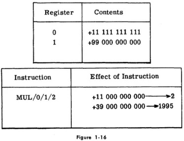
b; a, b, and c may be positive or nega-tive. Thus suppose that registersa
and 1 contain+
12 000 000 000 and + 13 000 000 000; the instruction MUL/0/1/2 will cause +01 560 000 000 to be put in register 2 (see Figure 1-15). This act may be interpreted in many different ways. For example, if+
12 000 000 000 in register 0 stands for+
12. 000 000 000 and + 13 000 000 000 in 1 stands for+
13. 000 000 000, then the number +01 560 000 000 which instructionRegister Contents
0 +12 000 000 000
1 +13 000 000 000
Instruction Effect of Instruction
MUL/0/1/2 +01 560 000 000~2