© 2017, IRJET | Impact Factor value: 6.171 | ISO 9001:2008 Certified Journal | Page 1435
Novelty method of speed control analysis of Permanent Magnet Brushless
DC Motor
R. Ganesan
1, Dr.S.Senthilkumar
2, F.Vijay Amirtharaj
3, S.Pandeeswari
41,3,4 Assistant Professor, Department of EEE,RVS college of Engineering and technology, Coimbatore.
2Assosiate Professor, Department of EEE, Bannari Amman Institute of Technology,Sathy.
---***---ABSTRACT: In this paper presents the parameter monitoring and speed control of Permanent Magnet Brushless DC Motor (PMBLDC) which is one of the best electrical drives that have increasing popularity, high efficiency, reliability, good dynamic response and it has very less maintenance [1]. Brushless DC motors become popular in every application from home appliances to aerospace industry. The PI controller is used for speed control of PMBLDC motor. The drive system fed from the PWM based Bridge Inverter, which gate pulses to be controlled by duty cycle ratio. The complete mathematical model of the drive system is developed and simulated using LabVIEW software.
Keywords: PMBLDC motor, PI controller, Duty cycle, LabVIEW, Speed control.
INTRODUCTION:
[image:1.612.346.557.318.449.2][1]Brushless DC motor (BLDC) is one kind of permanent magnet synchronous motor. Permanent magnet synchronous motors are classified on the basis of the wave shape of their induced emf, i.e, sinusoidal and trapezoidal. The sinusoidal type is known as permanent magnet synchronous motor and the trapezoidal type goes under the name of PM Brushless DC machine. Permanent magnet DC brush and brushless motors incorporate a combination of PM and electromagnetic fields to produce torque (or force) resulting in motion. Current in the DC motor is automatically switched to different windings by means of a commutator and brushes to create continuous motion. In a brushless motor, the rotor incorporates the magnets, and the stator contains the windings.
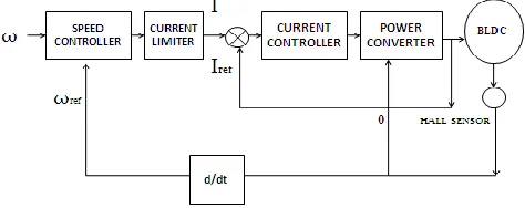
Figure: 1 Basic closed loop control
[1] Basic structure for closed loop control of the PMBLDC motor drive consists of an outer speed control loop, an inner current control loop for speed and current control respectively. Speed loop is relatively slower than the current loop. Hall Sensors detect magnetic fields, and can be used to sense rotor angle. The output is a digital 1 or 0 for each sensor depending on the magnetic field nearby which are mounted 120 degrees apart on the back of the motor.
[image:1.612.330.570.497.596.2]
Figure: 2 Elecronic commutator fed PMBLDC.
Figure : 3 Speed vs Torque characteristics
[image:1.612.51.288.600.694.2]© 2017, IRJET | Impact Factor value: 6.171 | ISO 9001:2008 Certified Journal | Page 1436 amplitude required to maintain the desired speed. When
using PWM outputs to control the six switches of the three-phase bridge, variation of the motor voltage can be achieved easily by changing the duty cycle of the PWM signal. In case of closed loop control the actual speed is measured and compared with the reference speed to find the error speed. This difference is given to the PI controller, which in turn determines the duty cycle. PMBLDC motor is popular in applications where speed the control is necessary and the current must be controlled to get desired torque.
1.1 Switching Sequences of Hall Sensor
Table: 1 Switching order of Hall sensor.
Hall A Hall B Hall C Phase
A Phase B Phase C
1 0 0 NC + -
0 0 0 + NC -
0 1 1 + - NC
0 1 0 NC - +
1 1 0 - NC +
where
NC: No connection +: Positive voltage
-: Negative voltage
1.2 PID Controller
[1] Proportional integral controller is a control loop feedback mechanism widely used on industrial control systems. The PI controller is the most commonly used feedback controller. A PI controller calculates an “error” value as the difference between a measured process variable and a desired set point. The combination of proportional and integral terms is important to increase the speed of the response and also to eliminate the steady state error. The proportional and integral terms are given by
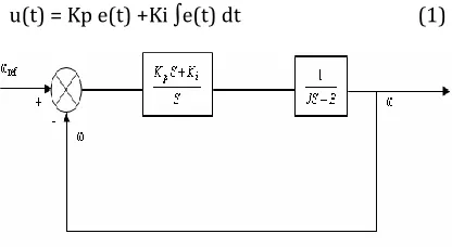
u(t) = Kp e(t) +Ki ∫e(t) dt (1)
Figure: 4 Block diagram of PI controller
The proportional term makes a change to the output that is proportional to the erroneous current error value. The proportional band response can be adjusted by multiplying the error by a constant Kp called the proportional gain. The model of PI speed controller is given by,
G(s) =Kp+(Ki / s) (2)
where G(S) is the controller transfer function.
The Kp is the proportional gain and Ki is the integral gain. The tuning of these parameters is done by using Ziegler Nichols method used. The specifications of the drive application are usually available in terms of percentage overshoot and settling time. The PI parameters are chosen so as to place the poles at appropriate locations to get the desired response. These parameters are obtained using Ziegler Nichols method which ensures stability[1].
[1]From the dynamic response obtained by simulation, the percentages of overshoot and settling time which are the measures of transient behavior, are obtained. The speed loop of the typical PMBLDC motor under no load condition of speed loop in a typical PMBLDC motor.
The closed loop transfer function of the system is given by
T(s) = (Kp S + Ki)/ [J (S2 + (B + Kp/J) S + (Ki /J )] (3)
where
T(s) : Closed loop transfer function Kp :Proportional gain
Ki : Integral gain. J: Moment of inertia B : Coefficient of friction.
1.3 Effects Of Co-Efficients
[image:2.612.57.265.578.692.2]
© 2017, IRJET | Impact Factor value: 6.171 | ISO 9001:2008 Certified Journal | Page 1437
1.4 Multi-Pulse Width Modulation
The gate signals are produced by comparing reference signal with triangular carrier wave. The frequency of the reference signal sets the output frequency (fo) and carrier frequency (fc).
1.5 PMBLDC Motor Speed Control
[1]In speed control applications position feedback is used in the position feedback loop. Velocity feedback can be derived from the position data. This eliminates a separate velocity transducer for the speed control loop. A PMBLDC motor is driven by voltage strokes coupled by rotor position. The rotor position is measured using Hall sensors. By varying the voltage across the motor, speed of the motor can be controlled. When using PWM outputs to control the six switches of the three-phase bridge, variation of the motor voltage can be obtained by varying the duty cycle of the PWM signal. The speed and torque of the motor depend on the strength of the magnetic field generated by the energized windings of the motor, which depend on the current through them, while adjusting the rotor voltage and current , motor speed is being varied.
Mathematical Modeling
For modeling and simulation purpose assumptions made are the common star connection of stator windings, three phase balanced system and uniform air gap. The mutual inductance between the stator phase windings are negligible when compared to the self-inductance and hence neglected in designing the model [12].
The PMBLDCM is modeled in the form of a set of differential equations given as
= R + p + (4)
= R + p + (5)
= R + p + (6)
In these equations, p represents the differential operator (d/dt), , and are currents, , and are flux linkages, and , and are phase-to-neutral back EMFs of PMBLDCM, in respective phases; R is the resistance of motor windings/phase. Moreover, the flux linkages can be represented as = − M ( + ) (7)
= − M ( + ) (8)
= − M ( + ) (9)
Where the self inductance/phase and M is is the mutual inductance of PMBLDCM winding/phase. The developed torque in the PMBLDCM is given as (10)
where is the motor speed in radians per second. Since PMBLDCM has no neutral connect + + = 0 (11)
From (4), (10) and (12), the voltage ( ) between the neutral point (n) and midpoint of the dc link (o) is given as = { + + − ( + + )} /3 (12)
From (7), (10) and (11), the flux linkages are given as = ( + M) , =( + M) , = ( +M) (13) From (4), (6) and (13), the current derivatives in generalized state-space form are given as p =( )/( +M) (14)
where, x represents phase a, b or c. The back EMF is a function of rotor position (θ) as = (15)
where, x can be phase a, b, or c and accordingly represents a function of rotor position with a maximum value ±1, identical to trapezoidal induced EMF, given as =1 for 0 < θ < 2π/3 (16)
= {(6/π) (π − θ)} − 1 for 2π/3 < θ < π (17)
= −1 for π < θ < 5π/3 (18)
© 2017, IRJET | Impact Factor value: 6.171 | ISO 9001:2008 Certified Journal | Page 1438
The functions and are similar to with
phase differences of 120◦ and 240◦ respectively.
Therefore, the electromagnetic torque expressed as
(20) The mechanical equation of motion in speed derivative form is given as
(21)
where is the derivative of rotor position θ, is the number of poles, is the load torque in newton meters, is the moment of inertia in kilogram square meters, and is the friction coefficient in newton meter seconds per radian. The derivative of rotor position is given as
(22)
Equations (4) to (22) represent the dynamic model of the PMBLDC motor.
3. Simulation
The Software used in the this paper is LabVIEW (Laboratory of Virtual Instrumentation Engineering Workbench). LabVIEW ties the creation of user interfaces (called front
panels) into the development cycle. LabVIEW
programs/subroutines are called virtual instruments (VIs). Each VI has three components: a block diagram, a front panel and a connector panel. The last is used to represent the VI in the block diagrams of other, calling VIs. Controls and indicators on the front panel allow an operator to input data into or extract data from a running virtual instrument. However, the front panel can also serve as a programmatic interface. Thus a virtual instrument can either be run as a program, with the front panel serving as a user interface, or, when dropped as a node onto the block diagram, the front panel defines the inputs and outputs for the given node through the connector panel. This implies each VI can be easily tested before being embedded as a subroutine into a larger program. The graphical approach also allows non-programmers to build programs by dragging and dropping virtual representations of lab equipment with which they are already familiar. The LabVIEW programming environment, with the included examples and documentation, makes it simple to create small applications.
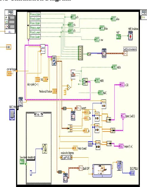
3.1 Simulation Diagram
Figure : 6 Graphical service code of Speed control of PMBLDC motor.
PMBLDC motor speed is controlled through the PWM switching pulse sequences of Bridge Inverter. According to the duty cycle, the speed range varied. The following table shows the varies speed for corresponding duty cycle ratio.
[image:4.612.326.573.91.406.2]3.2 Tabulation of Various Parameters
© 2017, IRJET | Impact Factor value: 6.171 | ISO 9001:2008 Certified Journal | Page 1439
3.3 Duty Cycle Vs Speed
[image:5.612.328.571.338.471.2]Figure: 7 Duty cycle vs Speed (rad/sec)
Figure 7 shows the relations between duty cycle and speed (rad/ sec). When the duty cycle ratio increased the corresponding speed value also increased.
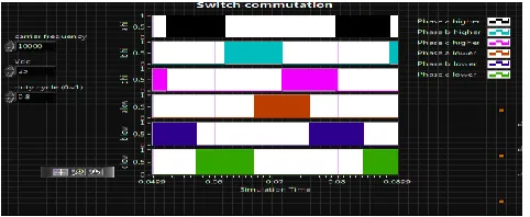
3.4 Switching Commutation
[image:5.612.43.284.415.514.2]The figure 8 shows the switching commutation of PWM based Bridge inverter. The upper and lower group of switches namely phases A, phase B, phase C Commutation sequences displayed. There are 6 sequences ,during the first interval switching commutation for Duty cycle 0.8 , Carrier frequency 10 kHz and DC voltage 25 V.
Figure: 8 Switching sequences of Bridge Inverter vs Time
3.5 Speed, Armature Current And Torque Characteristics
Figure : 9 Output waveforms of Speed , Armature current and Torque vs Time
The figure 9 shows the Speed, Armature current and Torque waveforms at duty cycle 0.8, carrier frequency 10kHz and DC voltage 25 V.
3.6 Rotor Speed
Rotor Speed graph represents the Speed (in rad/sec) vs time (in sec) . The speed of the motor has varied in between rated speed 0 to 150 rad/sec. At 0.089 sec Speed 81 rad/sec. By changing the duty cycle value in between 0 to 1 and obtain the various Speed range.
3.7 Armature Current and Torque
As shown in the figure 9 the speed precisely follows the acceleration ramp. At 0.084 sec the nominal load toque has applied 4.5 Nm. At 0.084 sec speed set at 80.2 rad/sec and the armature current 30 A. The mechanical load passes from 0 Nm to 10 Nm.
3.8 Back emf and Current Characteristics
Figure : 10 Output waveforms of Back emf and Current vs Time
Figure 10 shows the back emf and stator phase current waveforms taken for 0.8 duty cycle, for corresponding voltage and current values. Phase A voltage(VAB)=1.75V at 0.06 sec phase B voltage(VBC)=0.75V at 0.072 sec and Phase C voltage (VCA)=1.75V at 0.08 sec. Phase A current =80 A at 0.06 sec phase B current=49 A at 0.07 sec and phase C current -45 A at 0.06 sec. The phase current values are varied in between 0 to 100 A.
5. Conclusion
[image:5.612.37.290.563.685.2]© 2017, IRJET | Impact Factor value: 6.171 | ISO 9001:2008 Certified Journal | Page 1440
6. References
[1] MS. Julising“ Analysis The Speed Control Of Bldc Motor Drive Using Sensors”
[2] C. Sheeba joice, S.R. paranjothi and V.Jawahar senthil kumar(2013.) ” Digital control strategy for four quadrant operation of three phase BLDC Motor with Load variations”.
[3] Pooja Agarwal,Arpita Bose(2013)” PMBLDC motor speed control using PI and fuzzy controller”VIT Univ .
[4] Alexander rowe, Rourab sen Gupta.(2011) ” Instrumentation and control of a High Power BLDC Motor for Small vehicle applications”.
[5] M.V.Ramesh, J. Amarnath control of BLDC Motor by using fuzzy .”
[6 ] Lin Bai (2011) “Electric drive system with BLDC Motor”.
[7] Salih Baris Ozturk & Hamid A.Toliyat(2011),”Direct Torque and Indirect flux Control of Brushless DC Motor “.
[8] Tingna shi,Yuntao Guo,Peng Song and changliang xia,(2010) ”A New Approach of Minimizing Commutation Torque Ripple for Brushless DC Motor Based on DC-DC Converter”.
[9] Salih Baris Ozturk & Hamid A.Toliyat(2011), ”Direct Torque and Indirect flux Control of Brushless DC Motor”.
[10] Tingna shi,Yuntao Guo,Peng Song and changliang xia(2010), ”A New Approach of Minimizing Commutation Torque Ripple for Brushless DC Motor Based on DC-DC Converter”
[11] Jiancheng Fang,Wenzhuro and Haitao Li(2014) “Self_Compensation of the Commutation Angle Based on DC-Link Current for High_Speed Brushless DC Motors with Low Inductance”
[12] H.M.Cheshmehbeigi & e.Afje (2013) “Design Optimization of a Homopolar Salient-pole Brushless DC Machine Analysis,Simulation and Experimental Tests”.