© 2017, IRJET | Impact Factor value: 5.181 | ISO 9001:2008 Certified Journal | Page 74
Parametric study on behaviour of box girder bridges using CSi Bridge
Kiran Kumar Bhagwat
1, Dr. D. K. Kulkarni
2,
Prateek Cholappanavar
31
Post Graduate student, Dept. of Civil Engineering, SDMCET Dharwad, Karnataka, India
2
Professor, SDMCET Dharwad, Karnataka, India
3
Assistant
Professor, SDMCET Dharwad, Karnataka, India
---***---Abstract - Box girder bridges are the widely used bridge
deck systems because of cost effective and artistic solutions for over passage, under passage, separation structure and viaducts found in today’s modern highway systems. The behaviour of box girder bridges is complex in nature due to the non-uniform distribution of stresses in longitudinal and transverse directions. Recent literature on box girder bridges suggests that finite element method is suitable and effective in analyzing box sections. In this study linear analysis of three box girders (Rectangular, Trapezoidal and Circular) has been carried out using finite element software CSi Bridge 2017 as per Indian Road Congress (IRC) provisions. The behavior of box girders with uniform increments in depth has been discussed. Detailed study is conducted for various parameters such as deflection and longitudinal stress. The validity and accuracy of the present work has been also accessed by comparing the software results with manually calculated results.
Key Words: Box girder bridge, Non uniform distribution, Linear analysis, Longitudinal stress
1. INTRODUCTION
In box girder bridges the main beams consist of girders which are in the form of hollow box. The box girders may be of reinforced concrete, structural steel or pre-stressed concrete. The box is single cell, multi-cell or multi-spine with rectangular or trapezoidal cross-section. The main advantage of the box girders are mainly its structural efficiency due to high torsional rigidity by virtue of this a box girder can resist forces produced by the vehicular loading. The hollow section of the box girder can also be utilized for services such as water supply pipes, telephone lines, electric supply cables, sewers etc. and the section has an additional advantage as being light weight structure.
1.1 Methodology
1) Validation of rectangular box girder section by comparing the obtained results using CSi Bridge 2017 finite element software with manually calculated results.
2) Modeling and analysis of rectangular, trapezoidal and circular box girders for dead load and live load of IRC Class 70R loading using CSi Bridge 2017.
3) Parametric study for deflections, longitudinal bending stresses for the above cross-sections of the box girder bridges.
2. MODEL VALIDATION
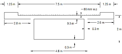
Courbon’s method is used for model validation in the present study. Courbon’s method is the rational method for determining the live load bending moments and shear forces in the bridge girders. This method is applicable when the span to width ratio of the deck is between 2 to 4.The dimensions of the box girder bridge which is used for model validation is as shown in Fig-1. The details of the box girder bridge is as given below
Span of the bridge = 20 m Width of the bridge = 10 m Width of carriageway = 7.5 m Thickness of pavement = 80 mm
Live load = IRC Class 70R tracked vehicle Grade of concrete = M 25
[image:1.595.312.561.528.638.2]Grade of steel = Fe 500
Fig -1: Cross sectional details of the box girder
Bending moments and shear forces obtained by manual calculations are compared with the CSi Bridge software results as shown in Table -1.
© 2017, IRJET | Impact Factor value: 5.181 | ISO 9001:2008 Certified Journal | Page 75
Table -1: Comparison of manual calculation and CSi Bridge software results
calculation Manual CSi Bridge Max. Dead load Shear Force (kN) 502.5 686.05 Max. Dead load Bending Moment
(kN-m) 2512.5 2356.4
Max. Live load Shear Force (kN) 529.25 651.9 Max. Live load Bending Moment
(kN-m) 2552.74 2341.7
3. ANALYSIS OF BOX GIRDER BRIDGES USING CSi
BRIDGE 2017
3.1 Box girder bridge details
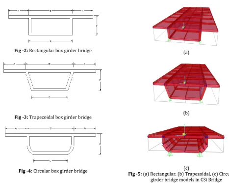
The present study involves analysis of 3 different cross sections of reinforced concrete box girder bridges such as rectangular, trapezoidal and circular box girder bridges using finite element package CSi Bridge 2017. The cross-sectional details of the box girder bridges are shown in Fig -2, Fig -3 and Fig -4 and Table -2.
Fig -2: Rectangular box girder bridge
[image:2.595.53.521.380.752.2]Fig -3: Trapezoidal box girder bridge
Fig -4: Circular box girder bridge
Table -2: Geometries of bridges used in parametric study(Units = m)
Rectangular Trapezoidal Circular
A B C A B C A B C
2 2.4 4.8 4.8 1.8 6 4.6 2 5.6 3.2 2.4 2.4 4.8 4.8 1.8 6 4.7 2.2 5.2 2.8 2.8 2.4 4.8 4.8 1.7 6.2 4.6 2 5.6 2.6
The box girder bridges considered for analysis are such that in which width of bridge deck and area of cross section are kept constant only the depth is varied. The span of the bridge is taken as 20 m for all types of box girder bridge sections. A constant thickness of 0.3 m is considered for all the bridge cross-sections. M30 concrete and Fe500 steel are used as material properties. Linear analyses of box girder bridges are carried out for dead load and live load (IRC Class 70R loading) for all the three cross-sections of the bridges using finite element software CSi Bridge. Fig. -5 shows the rectangular, trapezoidal and circular box girder bridge deck models in CSi Bridge.
(a)
(b)
(c)
© 2017, IRJET | Impact Factor value: 5.181 | ISO 9001:2008 Certified Journal | Page 76
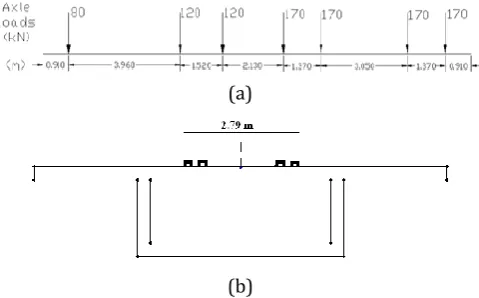
3.2 Loading placement
It is found that the critical moment was generated for IRC Class 70R wheeled vehicle loading; therefore, parametric study is done by placing Class 70R wheeled vehicle loading.IRC loadings are placed at mid span of the bridge i.e zero eccentricity for which the stress is maximum at
mid
span. Fig -6 shows longitudinal and transverse placement of
IRC Class 70R loading.(a)
(b)
Fig -6: Longitudinal placement, (b) transverse placement of IRC 70R loading
4. PARAMETRIC STUDY
Parametric study is conducted for the analysis of Rectangular, Trapezoidal and Circular box girder bridges. Linear analysis of the above cross sections of box girder bridges (for depths 2 m, 2.4 m, 2.8 m) for the load combination (DL+LL) is carried out in CSi Bridge (Live load = IRC 70R loading). The live load is placed on the bridge decks as per IRC: 6- 2000. The parameters such as deflections and longitudinal bending stress in top flange and bottom flange of the box girder are compared for 2 m, 2.4 m and 2.8 m depth of box girder bridge decks.
4.1 Rectangular box girder
Table 4 present the comparison of the results of maximum deflection, maximum bending stress at top flange (S11) and
maximum bending stress at bottom flange (S22) for
rectangular box girder of different depths for live load placed centrally.
Table -4:Comparison of rectangular box section
Depth Deflection S11 (kN/m2) S22 (kN/m2)
2 m 5.54 3068.99 2667.05
2.4 m 3.50 2286.30 2055.77
2.8 m 3.09 2040.12 1684.74
[image:3.595.322.544.146.277.2]Figure 7 to 9 shows variation of vertical deflection, longitudinal bending stress along the span in top flange and bottom flange for dead load and IRC 70R loading.
[image:3.595.41.281.230.379.2]Fig -7: Comparison of deflection in rectangular box girder
Fig -8:Comparison of longitudinal bending stress in top flange of the Rectangular box girder
Fig - 9: Comparison of longitudinal bending stress in bottom flange of the Rectangular box girder
[image:3.595.320.548.299.444.2] [image:3.595.318.550.499.635.2]© 2017, IRJET | Impact Factor value: 5.181 | ISO 9001:2008 Certified Journal | Page 77
4.2 Trapezoidal box girder
Table 5 present the comparison of the results of maximum deflection, maximum bending stress at top flange (S11) and
maximum bending stress at bottom flange (S22) for
trapezoidal box girder of different depths for live load placed centrally.
Table -5: Comparison of trapezoidal box section
Depth Deflection(mm) S11 (kN/m2) S22 (kN/m2)
2 m 6.41 3108.04 2678.58
2.4 m 4.51 2479.32 2044.91
2.8 m 3.70 2062.70 1676.07
In Trapezoidal box girder bridge, the maximum deflection at mid span of the box girder deck decreases by 29.7% and 42.3% for 2.4 m and 2.8 m depth respectively with respect to 2 m depth box girder and the maximum bending stress at mid span of the box girder decreases by 24.2% and 35.16% for 2.4 m and 2.8 m depth respectively with respect to 2 m depth box girder.
4.3 Circular box girder
Table 6 present the comparison of the results of maximum deflection, maximum bending stress at top flange (S11) and
maximum bending stress at bottom flange (S22) for circular
box girder of different depths for live load placed centrally.
Table -6:Comparison of circular box section
Depth Deflection(mm) S11 (kN/m2) S22 (kN/m2)
2 m 6.38 3268.42 2649.42
2.4 m 5.08 2598.56 2099.39
2.8 m 4.62 2226.58 1613.02
In Circular box girder bridge, the maximum deflection at mid span of the box girder deck decreases by 20.3% and 27.5% for 2.4 m and 2.8 m depth respectively with respect to 2 m depth box girder and the maximum bending stress at mid span of the box girder decreases by 23.35% and 35.48% for 2.4 m and 2.8 m depth respectively with respect to 2 m depth box girder.
4.4 Comparison of Rectangular, Trapezoidal and
Circular box girder bridges
Following tables and figures show the comparison of Rectangular, Trapezoidal and Circular box girder bridges subjected to IRC 70R loading (centrally placed) in terms of deflections, longitudinal stress in top and bottom flange of the box girders of depth 2m, 2.4m and 2.8m.
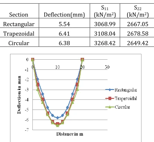
1) 2m depth section
Table -7:Comparison of 2.0m depth three cross sectional shape of box girders
Section Deflection(mm) (kN/mS11 2) S 22
(kN/m2)
Rectangular 5.54 3068.99 2667.05
Trapezoidal 6.41 3108.04 2678.58
[image:4.595.322.545.390.532.2]Circular 6.38 3268.42 2649.42
[image:4.595.325.546.579.723.2]Fig -10: Comparison of deflections in 2 m depth box girders
Fig -11: Comparison of longitudinal bending stress in top flange of 2 m depth box girders
© 2017, IRJET | Impact Factor value: 5.181 | ISO 9001:2008 Certified Journal | Page 78 In 2 m depth sections, maximum deflection at mid span of the
Circular box girder is 11.5% and 1.84% higher than Rectangular and Trapezoidal box girder sections respectively and maximum longitudinal bending stress at the mid span of the Circular box girder is 6.10% and 4.9% higher than Rectangular box girder and Trapezoidal box girder respectively.
[image:5.595.320.550.73.249.2]2) 2.4 m depth section
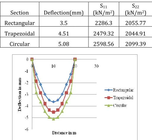
Table -8:Comparison of 2.4m depth three cross sectional shape of box girders
Section Deflection(mm) (kN/mS11 2) S 22
(kN/m2)
Rectangular 3.5 2286.3 2055.77
Trapezoidal 4.51 2479.32 2044.91
[image:5.595.35.292.257.494.2]Circular 5.08 2598.56 2099.39
Fig -12: Comparison of deflections in 2.4 m depth box girders
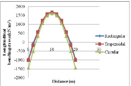
Fig -13: Comparison of longitudinal bending stress in top flange of 2.4 m depth box girders
Fig -14: Comparison of longitudinal bending stress in bottom flange of 2.4 m depth box girders
In 2.4 m depth sections, maximum deflection at mid span of the Circular box girder is 28.48% and 11.22% higher than Rectangular and Trapezoidal box girder sections respectively and maximum longitudinal bending stress at the mid span of the Circular box girder is 12.05% and 4.6% higher than Rectangular box girder and Trapezoidal box girder respectively.
[image:5.595.310.552.446.695.2]3) 2.8m depth section
Table -9:Comparison of 2.8m depth three cross sectional shape of box girders
Section Deflection(mm) (kN/mS11 2)
S22
(kN/m2)
Rectangular 3.09 2040.12 1684.74
Trapezoidal 3.7 2062.7 1676.07
Circular 4.62 2226.58 1613.02
[image:5.595.52.272.540.685.2]© 2017, IRJET | Impact Factor value: 5.181 | ISO 9001:2008 Certified Journal | Page 79
Fig -16: Comparison of longitudinal bending stress in top flange of 2.8 m depth box girders
Fig -17: Comparison of longitudinal bending stress in bottom flange of 2.8 m depth box girders
In 2.8 m depth sections, maximum deflection at mid span of the Circular box girder is 30.7% and 19.9% higher than Rectangular and Trapezoidal box girder sections respectively and maximum longitudinal bending stress at the mid span of the Circular box girder is 8.37% and 7.36% higher than Rectangular box girder and Trapezoidal box girder respectively.
3. CONCLUSIONS
From the above discussions the following conclusions are made
1) As the depth of the box girder increases the deflection and stress in box girder bridge decreases but not in proportion with depth increment.
2) So among the three cross sections of the box girder bridges the deflection and bending stress is lowest in Rectangular box girder bridge and highest in Circular box girder bridge.
3) Therefore it can be concluded that stiffness and strength of the Rectangular box girder bridge is more as compared to the Trapezoidal and Circular box girder bridge.
REFERENCES
[1] Sennah K.M. and Kennedy J.B. “Literature review in analysis of box-girder bridges”, Journal of Structural Engineering ASCE, No. 10, 1061(2002) pp.1084-702.
[2] Park N. H., Choi S. and Kang Y. J. “Exact distortional behavior and practical distortional analysis of multicell box girders using an expanded method”, Computers and Structures, ELSEVIER Journals , No. 83 (2005), pp. 1607– 1626
[3] Zakia B. “Analysis and Behavior Investigations of Box Girder Bridges”, M. Tech. Thesis, Indian Institute of Technology Roorkee, Roorkee, India, 2010.
[4] Ibrahim A. and Salim H. “Finite-element analysis of reinforced-concrete box girder bridges under close-in detonations”, Journal of Structural Engineering ASCE, No.10.1061 (2013), pp. 1943-5509.
[5] Hamed E. and Frostig Y. “Free vibrations of multi-girder and multi-cell box bridges with transverse deformations effects”, Computers and Structures, ELSEVIER Journals.No.279 (2015), pp. 699–722.
[6] Zhang Y.H. and Lin L.X. “Shear lag analysis of thin-walled box girders adopting additional deflection as generalized displacement”, Journal of Structural Engineering ASCE, No.10.1061(2014), pp. 1943-7889.
[7] Bien J., Kuzawa M. and Kaminski T. “Validation of numerical models of concrete box bridges based on load test results”, Archieves of Civil and Mechanical Engineering, ELSEVIER Journals, No.15(2015), pp. 1046-1060.
[8] IRC: 6-2000, Standard Specifications and Code of Practice for Road Bridges, Section II, Loads and Stresses, The Indian Roads Congress, 2000.
[image:6.595.51.274.298.444.2]