© 2017, IRJET | Impact Factor value: 5.181 | ISO 9001:2008 Certified Journal | Page 2526
INTELLIGENT HELMET BAND
Takshashila Hadke
1, Minakshee Kharwade
2, Parul Nagarkar
3, Assistant Prof. V.V.Panchbhai
41,2,3
Student, Dept. of Electronics and Telecommunication Engineering, Priyadarshini College of
Engineering, Nagpur
4
Assistant Professor, Dept. of Electronics and Telecommunication Engineering, Priyadarshini College of
Engineering, Nagpur, Maharashtra, India
---***---Abstract -Now a day’s technology is growing very fast so our life become easier. The advance technology has increased the traffic hazards and road mishaps takes place frequently, due to which huge loss of life and property because of poor medical facility. Intelligent helmet band will provide an optimum solution to this drawback .The intelligent helmet band is an idea which makes motorcycle driving safer than before. This is implemented using GSM and GPS technology. The working of intelligent helmet band is very simple. Limit switch is placed in the helmet which will detect whether the rider has worn the helmet or not, if not then the bike will not start. According to this project when a rider meets with an accident immediately the accelerometer detects the signal and a short message along with location of the rider will be send to the predefined number using GSM modem.
Key Words: (GSM, GPS), Limit switch, Bluetooth,
Accelerometer, Microcontroller ATMEGA 16, Microcontroller ATMEGA8 (SMD).
1. INTRODUCTION
In today’s era especially in the young generation, the craze of motorbikes is really remarkable. As the bikers in our country are increasing, the road accidents are also increasing day by day, due to which many deaths occurs, most of them are cause by not wearing helmet and also due to poor medical facility. So providing safety to a person while riding the bike is of prime concern. Thus by considering these problems the intelligent helmet band makes the rider necessary to wear the helmet while driving the bike, if not the bike won’t start.
2. LITERATURE WORK
Jennifer William et al. [1] proposed system in which the intelligent helmet ensures the safety of the biker by making it necessary to wear the helmet and assure that rider hasn’t consume any alcohol while driving the vehicle. The system also help in efficient handling of aftermath of accident by sending a SMS with the location of the biker to person’s well-wisher’s number to get proper and prompt medical attention, after meeting with an accident.
C. Prabha et al. [2] introduced system which can be used as a crash or rollover detector of the vehicle during and after a crash. When the vehicle meets with an accident the sensor in
the system detects and alert system with SMS to the user defined mobile number. The GPS tracking and GSM alert based algorithm is designed and implemented in embedded system domain. The proposed vehicle accident detection system trace the location of the rider automatically and sends an alert message regarding accident.
Manjesh N et al. [3] demonstrated the smart helmet working, which makes the motorcycle driving safer than before. It uses GSM and GPS technology. Sensors are placed at different places of helmet, so when the rider crashes and the helmet hits the ground the sensor sense and sends the signal to the microcontroller. The controller extracts GPS data and then GSM module send message to the predefined number.
Asaad M. J. et al. [4] research was carried out to design a hardware and software of the GPS based on GSM network. The proposed GPS/GSM based system has the two parts, first is a mobile unit and another is controlling station. The system, interfaces, connections, data transmission and reception of data among the mobile unit and control stations are successfully working. These results are compatible with GPS technologies.
3. PROPOSED SYSTEM
[image:1.595.312.548.542.645.2]Transmitter:
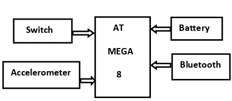
Fig. 1: Block Diagram of Transmitter
Fig.1 shows the block diagram of transmitter which contains switch, accelerometer, battery, bluetooth and microcontroller AT mega 8. Limit switch will detect whether the biker worn the helmet or not. Accelerometer used to measures the static and dynamic acceleration such as tilt-sensing application, motion, shock or vibration. Bluetooth is used to set up the wireless serial connection.
Switch
AT
MEGA
8
Battery
Accelerometer
Bluetooth
© 2017, IRJET | Impact Factor value: 5.181 | ISO 9001:2008 Certified Journal | Page 2527 Microcontroller sends the appropriate data to the receiver
through bluetooth.
[image:2.595.41.258.149.242.2]Receiver:
[image:2.595.48.550.333.749.2]Fig. 2: Block Diagram of Receiver
Fig.2 describes the block diagram of receiver which consist of SIM 808 module, relay, bluetooth, ignition circuit, microcontroller ATmega 16. SIM 808 has inbuilt GSM and GPS. Ignition circuit will start after rider has worn the helmet. Bluetooth is used to receive the signal from the transmitter bluetooth. Relay used for buzzer and ignition purpose.
PCB of Transmitter and Receiver
Fig.3: Transmitter PCB
Fig.4: Receiver PCB
4. PROPOSED METHODOLOGY
In this system following components are used:
4.1 Microcontroller
Atmega 16 and Atmega 8 is high performance, low power Atmel AVR 8 bit microcontroller based on enhanced RISC architecture with 16KB(for Atmega 16) and 8KB(for Atmega 8) flash 512bytes EEPROM 1KB of SRAM. By executing powerful instruction in a single clock cycle, the ATMEGA 16 achieves throughputs approaching 1MIPS per MHz. AVR microcontrollers find many applications as embedded systems.
4.2 GSM/GPS Module SIM808 GSM/GPS
SIM808 is integrated with a high performance GSM engine and GPS engine. The GSM/GPS engine is a quad-band GSM/GPS module that works on frequencies GSM 850 MHz.
Fig.5: SIM 808 Module
Fig.6: Assembly of Transmitter
SIM 808
AT
MEGA
16
Relay
[image:2.595.324.555.344.525.2] [image:2.595.46.276.390.553.2]© 2017, IRJET | Impact Factor value: 5.181 | ISO 9001:2008 Certified Journal | Page 2528
Fig.7: Assembly of Receiver
Fig.8: Accident Alert Message with Longitude and Latitude
• Sending messages using GSM default alphabet
For sending the text message following AT commands are used in the project:
Table 1. GSM AT commands
• GPS At commands
Following GPS commands are used to read location of parameters in the project:
Table 2. GPS AT commands
4.3 ACCELEROMETER
The ADXL335 is a small, thin, low power, complete 3-axis accelerometer with signal conditioned voltage outputs. It measures the acceleration with a minimum full-scale range of ±3g. It can use to measure the static acceleration of gravity in tilt-sensing applications, as well as dynamic acceleration measured from motion, shock, or vibration. Accelerometer is operated at 0.1 KHz bandwidth.
Fig.9: Functional block diagram of Accelerometer
5. ALGORITHM
Following is the algorithm for working of the project: Step1)
As the transmitter is turned on the switch (i.e. Limit switch) will check whether the rider has worn the helmet or not.
Step 2)
The switch will verify that rider has worn the helmet if yes then it will provide ignition to the bike and if not then the bike won’t start.
Step 3)
After providing the ignition accelerometer will monitor the change in velocity.
Command Description Response
AT To check the
module OK
AT+CGNSPWR=? GPS power
control OK
AT+CGNSINF Get current GPS location info
Response <GNNS run status>,<Fix status>, <UTC date &
Time>,<Latitude>, <Longitude>,<MS L
Altitude>,<Speed Over Ground> OK
Command Description
AT Make sure that module is
working properly.
AT+CMGF=1 Use for SMS Configuration.
AT+CMGS=”phone
number” Set the message transmission number and send
SMS message. After receiving symbol >, a message (end with 0x1A) can be sent .
0x1A This is a terminator. Before
sending it , you
[image:3.595.46.260.100.276.2] [image:3.595.309.565.123.350.2] [image:3.595.328.534.473.568.2]© 2017, IRJET | Impact Factor value: 5.181 | ISO 9001:2008 Certified Journal | Page 2529 Step 4)
If the value of accelerometer changes with respect to the threshold value then it will detect as an accident and the ignition of the bike will get cut.
Step 5)
After accident detection the message is send to the predefined number along with the location of the rider through GSM if not the accelerometer will continuously monitor for the accident.
Step 6)
The microcontroller will check if any false trigger has occurred or not if occurred then it will again verify step 2.
6. WORKING
Fig.10: Final assembly of project
Fig.11: Project Module
In this system ATMEGA16 and ATMEGA8 microcontroller are used .When the system is switched on, firstly Limit switch is used to check whether the driver has worn the helmet or not. If not it will not allow to start the bike. In normal condition when the helmet is worn, signal from the transmitter through bluetooth is send to the receiver which will enable the ignition circuit along with accelerometer and GPS. So when the rider wills meets with an accident the accelerometer detects the change in axis (x, y, z) after which the microcontroller sends the message through the GSM modem including the location to the predefined number. The message will give the information of longitude and latitude values using these values position of the vehicle can be estimated.
7. ADVANTAGES
Following are the advantages of developed system: 1.Operation of intelligent helmet band is easy. 2. The designing of band is simple and reliable. 3.Intelligent band can be used with different types of
helmet for motorbikes.
4.This band provides an additional safety feature in the helmet.
8. RESULT
Following is the comparison between our proposed system and reference
[image:4.595.48.264.277.491.2]
Table 3. Result of Comparison.
Parameter Ref[1] Ref[2] Ref[3] Proposed System Controller/
Processor Used
ATMEG
A328 ARM7 P89V51RD2 ATMEGA 16 & ATMEGA 8 Helmet
detection sensor
IR
sensor - Pressure sensor Limit switch
Accident detection sensor
Acceler
ometer Piezoelectric sensor
Vibratio
n sensor Accelerometer
Position
sensor Not Specifie d
Not Specifie d
Not
specified Sim808
GSM
module SIM900A Not Specifie d
Sim300 Sim808
Tx & Rx communica tion technology
ASK 434MH z
RF transmit ter and RF receiver
Not
© 2017, IRJET | Impact Factor value: 5.181 | ISO 9001:2008 Certified Journal | Page 2530
9. CONCLUSION
Intelligent helmet band assures the safe journey to the rider that would reduce the injuries and it ensures that the biker has worn the helmet. In case of accident the project will help to notify instant medical facility thus it helps to reduce death ratio due to lack of immediate medical facility on time.
REFERENCES
[1] Jennifer William, Kaustubh Padwal , Nexon Samuel, Akshay Bawkar, Smita Rukhande,”Intelligent Helmet”,International Journal of Scientific & Engineering Research, Volume 2, Issue 3, March 2016.
[2] C. Prabha, R.Sunita, R. Anita “Automatic Vehicle Accident Detection and Messaging System Using GSM & GPS Modem”, Assistant professor, Dept. of ECE, Bellari Institute of Technology and Management, Bellary, Karnataka, Volume 3, Issue 7, July 2014.
[3] Manjesh N, Prof. Sudarshan Raj “Smart Helmet Using GSM and GPS Technology for Accident Detection & Reporting System”, M tech, ECE –DSCE, JNTUA Hindupur, HOD and Ass. Prof. BIT-IT, Hindupur, India, Volume 2, Issue 4, pp:(122-127), Oct –Dec 2014. [4] Asaad M.J. Al-Hindawi, Ibraheem Talib, “Experimentally
Evaluation of GPS/GSM Based System Design”, Journal of Electronic Systems Volume:2 Number, 2 June 2012. [5] Prof. Chitte P.P., Mr Salunke Akshay S., Mr Thorat
Anirudha N, Mr. Bhosale, Nilesh T., “Smart Hekmet And Intelligent Bike System”, International Research Journal Of Engineering & Technology(IRJET), Volume:03, Issue:05, May 2016.
[6] Bindu Sebastian Priyanka Kp, Hridhya Kuttikrishanan, “Smart Helmet” International Journal Of Technology & Advanced Engineering, Volume5, Issue:12, December 2015.
BIOGRAPHIES
Takshashila Hadke, B.E final year, Dept. Of Electronics and Telecommunications Engineering, Priyadarshini college of Engineering, Nagpur.
Minakshee Kharwade, B.E final year, Dept. Of Electronics and Telecommunications Engineering, Priyadarshini college of Engineering, Nagpur.
Parul Nagarkar, B.E final year, Dept. Of Electronics and Telecommunications Engineering, Priyadarshini college of Engineering, Nagpur.
Assistant Professor V.V.Panchbhai,