http://dx.doi.org/10.4236/am.2014.518274
How to cite this paper: Go, J. and Lee, J.-H. (2014) Application of FVM Analysis for Elastic Characteristics on Cutting Process of a Composited Coating Iron. Applied Mathematics, 5, 2881-2887. http://dx.doi.org/10.4236/am.2014.518274
Application of FVM Analysis for Elastic
Characteristics on Cutting Process of a
Composited Coating Iron
Jaegwi Go1*, Je-Hyun Lee2
1Department of Mathematics, Changwon National University, Changwon, Korea 2School of Nano and Advanced Materials Engineering, Changwon National University,
Changwon, Korea
Email: [email protected], *[email protected]
Received 20 August 2014; revised 25 August 2014; accepted 12 September 2014
Copyright © 2014 by authors and Scientific Research Publishing Inc.
This work is licensed under the Creative Commons Attribution International License (CC BY). http://creativecommons.org/licenses/by/4.0/
Abstract
A composite material as a work piece is taken into account to investigate the elastic characteristics displaying during the cutting process. The magnitude of the elastic behaviors such as displace-ments and stresses reacts sensitively to the cutting angle and the vertical force increase, and the magnitude increases along the increments of the cutting angle and the vertical force increase. The buffering mechanism at the bond coat is described well by the fluctuation phenomenon for the ho-rizontal displacement distribution profiles at the substrate. The variation of cutting angle under high vertical force yields profound influence on the behaviors of the longitudinal stress and the shear stress.
Keywords
Composite Material, Cutting Angle, Finite Volume Method, Thermoelastic Characteristics, Vertical Force
1. Introduction
Analysis of the contact-zone behavior between the cutting tool and the work piece is a crucial task to inspect and idealize a metal machining. The surface intensity of the machined work-piece is wrapped up in the chip forma-tion zone, and the contact condiforma-tion between the cutting tool rake face and the chip bestows profound influences on tool wear [1]. Moreover, surface layer state of the worn tools is needed to be considered to understand the
different wear mechanisms occurring in the cutting zone.
The geometry of the cutting edge is an important factor to determine elastic characteristics such as stresses, strain, and displacements. The elastic characteristics on the machining forces, material flow, and temperature distribution in the cutting zone were investigated by Denkena et al. [2] using symmetrical and asymmetrical round cutting edge. Keyvan et al. [3] analyzed the effective geometry of the cutting edge prior to cutting by em-ploying the circular regression method. A sensibility analysis to geometric and cutting conditions was carried out by Rodrigues et al. employing particle finite element method [4], and the influence of cutting parameters on cutting forces generated during the turning of aluminium alloy (UNS A97075) work pieces was studied by Agustina et al.[5].
The micro structural characterizations of work piece play an important role to determine the thermal and me-chanical properties, which influence the elastic behavior such as displacements, strain, and stresses. Wallbank [6]
examined the elastic characteristics of layer’s microstructure using different work piece materials, and investiga-tion on the interface between the build-up edge and the cutting tool was performed by Kummel et al. [7]. In the present work, the elastic characteristics of a composite material as a work piece appearing during the cutting process. Various cutting forces and angles are chosen for the analysis of elastic behavior. The composite materi-al was prepared through an air plasma spray, and METECO 204 NS powder is adopted for the top coat of TBCs. A couple of partial differential equations are derived based on the thermal elastic theory. Due to the complexity of the governing equations, a finite volume approach [8] is applied to analyze the elastic characteristics.
2. Mathematical Modelling
2.1. Mathematical DerivationTwo-dimensional cutting models are taken into account to investigate the cutting-zone behavior. The work piece is a composite material composed of the top coat, the bond coat, and the substrate, and subjecting to a vertical loading due to the cutting tool (see Figure 1).
Under the assumption of the vertical loading, the equilibrium equation for the plane elasticity problems can be expressed as
0 xy x
x y
τ
σ ∂
∂
+ =
∂ ∂ (1a)
0
y xy
y x
σ τ
∂ ∂
+ =
∂ ∂ . (1b)
The σx, σy, and τxy are x-directional, y-directional, and shear stress, respectively. The strain compo-
nents in terms of deformation components are
, , .
x y xy
u v u v
x y y x
ε =∂ ε =∂ γ =∂ +∂
∂ ∂ ∂ ∂ (2)
where u and v are the displacement components in the x- and y-directions, respectively. Based on the Hooke’s law the plane strain-stress relations are written by
(
)
2 1
1 1
, , .
x x y y y x xy xy
E E E
ν
ε = σ −νσ ε = σ −νσ γ = + τ (3)
The combination of Equations (1)-(3) leads to the following governing equations
(
)
2 2 2
2 2 0
u v u
K K G G
x y
x ν y
∂ + + ∂ + ∂ =
∂ ∂
∂ ∂ (4a)
(
)
2 2 2
2 2 0
v u v
G K G K
x y
x ν y
∂ + + ∂ + ∂ =
∂ ∂
∂ ∂ , (4b)
where 2
1
E K
ν
=
− and 2 1
(
)
E G
ν
=
+ . E and ν represent the Elastic modulus and Poisson’s ratio, respect- tively.
Since the governing equations too complex to obtain the analytic solution, a finite volume method is applied for the numerical sketches. The elastic characteristics are displayed based on the following boundary conditions:
1) x=0, 0≤ ≤y M; u=0.
2) 0≤ ≤y M; u=0.
3) , , cos , sin .
2 x y
L
x= y=M σ =P θ σ =P θ
The P and θ on the boundary condition 3) imply vertical force and cutting angle, respectively.
2.2. Finite Volume Formulation
Due to complexity of the governing equation a finite volume method is applied for the approximation. The do-main is divided up into control volume and integrates the field equations over each control volume. The discre-tizations for the governing equations are developed based on the following relations at the adjacent locations:
(
)
(
)
, 1 , , , 1 , 1 , 1
1 1
, , , 1
2 2
, 1, 2, 1 , 1 , 1 1, 1 2, 1
, 1 , 2 1 1 , 1 2 , , , 2 1 1
3 4 , 3 4 ,
2 4
i j i j i j i j i j i j
i j i j i j
i j i j i j m j m j m j m j
m j i j
m m j
u u u u u u
u u u
r r r r r r
w
w w w w w w w w
z z w w + − + − + − − − − + + + + − + − + − − + − − − ∂ ∂ ∂ = = = ∂ ∆ ∂ ∆ ∂ ∆ ∂ = − + = + − + ∂ ∆
= , 1
(
, 1 2, 1)
1 1 1 1, , 1 ,
2 2 2 2
1 1
, .
4 2
j m j m j
i j i j i j
w w φ φ φ
+ + − + + + + + +
+ − = +
The finite surface mesh is denoted by
( )
i j, and the subscript 1 2 presents the value of the displacement at the boundary of the control surface (see Figure 2). Based on the above relations at the adjacent locations the Equation (4) are discretized as below11 1, 12 , 1 13 , 1 14 1, 15 , 11 , 1 12 1, 1 13 2, 1 14 , 15 1, 16 2,
17 , 1 18 1, 1 19 2, 1
0.
i j i j i j i j i j i j i j i j i j i j i j
i j i j i j
A u A u A u A u A u B v B v B v B v B v B v
B v B v B v
+ + − − + − + − + − −
− − − − −
+ + + + + + + + + +
Figure 2. Finite volume mesh for a two-dimen- sional domain.
21 1, 22 , 1 23 , 1 24 1, 25 , 21 , 1 22 1, 1 23 2, 1 24 , 25 1,
26 2, 27 , 1 28 1, 1 29 2, 1
0.
i j i j i j i j i j i j i j i j i j i j
i j i j i j i j
A v A v A v A v A v B u B u B u B u B u
B u B u B u B u
+ + − − + − + − + −
− − − − − −
+ + + + + + + + +
+ + + + = (5b)
with the following coefficients:
(
)
(
)
(
)
(
)
(
)
(
)
(
)
(
)
(
)
11 12 13 14 15
11 12 13 14 15
16 17 18 19
21 22
, , , , 2 2 ,
5 3 10
, , , , 2 ,
8 8 8
6 5 3
, , , ,
8 8 8
,
y x x y y x
A K A G A G A K A K G
x y y x x y
B K G B K G B K G B K G B K G
B K G B K G B K G B K G
y x
A G A K
x
ν ν ν ν ν
ν ν ν ν
∆ ∆ ∆ ∆ ∆ ∆
= = = = = − −
∆ ∆ ∆ ∆ ∆ ∆
= + = − + = + = − + = +
= − + = + = − + = +
∆ ∆
= =
∆ ∆
(
)
(
)
(
)
(
)
(
)
(
)
(
)
(
)
(
)
23 24 25
21 22 23 24
25 26 27 28 29
, , , 2 2 ,
5 3 10
, , , ,
8 8 8
6 5 3
2 , , , , .
8 8 8
x y y x
A K A G A G K
y y x x y
B K G B K G B K G B K G
B K G B K G B K G B K G B K G
ν ν ν ν
ν ν ν ν ν
∆ ∆ ∆ ∆
= = = − −
∆ ∆ ∆ ∆
= + = − + = + = − +
= + = − + = + = − + = +
3. Results and Discussions
[image:4.595.115.524.320.492.2]The work piece is a composite material and the mechanical and thermal properties for each layer are shown in
Table 1. For the analysis of the elastic characteristics of the work piece the representative cutting angles: 107
A= , 123, and the vertical forces: P=100N ,P=500N are chosen. The finite volume model developed in Section 2.2 applied with the step size 200/20 and 11/100 mm, respectively, for the radius x and longitudinal y to obtain the numerical solutions.
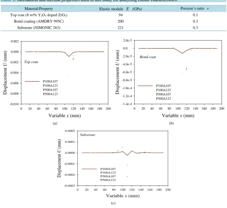
The work piece is a composite material and the mechanical and thermal properties for each layer are shown in
Table 1. For the analysis of the elastic characteristics of the work piece the representative cutting angles: 107
A= , 123, and the vertical forces: P=100N, P=500N are chosen. The horizontal displacement
dis-tribution profiles are presented in Figure 3.
Table 1. Mechanical and thermal properties used in this study for analyzing elastic characteristics.
Material/Property Elastic module E (GPa) Poisson’s ratio ν Top coat (8 wt% Y2O3 doped ZrO2) 94 0.1
Bond coating (AMDRY 995C) 200 0.3
Substrate (NIMONIC 263) 221 0.3
Top coat
Variable x (mm)
0 20 40 60 80 100 120 140 160 180 200
D
isp
la
ce
me
n
t
U
(
mm)
-0.010 -0.008 -0.006 -0.004 -0.002 0.000 0.002
P100A107 P100A123 P500A107 P500A123
Bond coat
Variable x (mm)
0 20 40 60 80 100 120 140 160 180 200
D
isp
la
ce
me
n
t
U
(
mm)
-1.4e-4 -1.2e-4 -1.0e-4 -8.0e-5 -6.0e-5 -4.0e-5 -2.0e-5
0.0 2.0e-5
P100A107 P100A123 P500A107 P500A123
(a) (b)
Substrate
Variable x (mm)
0 20 40 60 80 100 120 140 160 180 200
D
isp
la
ce
me
nt
U
(mm)
-0.0003 -0.0002 -0.0001 0.0000 0.0001 0.0002
P100A107 P100A123 P500A107 P500A123
(c)
Figure 3. Horizontal displacement distribution profiles: (a) At the top coat; (b) At bondcoat; (c) At the substrate.
dinal displacement distribution profiles. The longitudinal displacement occurs at the boundary only, and the magnitude of the longitudinal displacement is getting larger as the cutting angle and the vertical force increase.
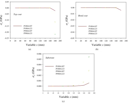
The horizontal stress distribution profiles are displayed inFigure 5. At the top coat the horizontal stress is tri-vial until the variable x≤160 mm and the domain is under the loading of the compressive stress around the boundary (seeFigure 5(a)). As the cutting angle and vertical force increase a larger horizontal stress develops. As shown inFigure 5(b) the horizontals tress for the bond coat describes similar aspect to the top coat. Howev-er, the substrate is under the action of tensile horizontal stress. Even though the magnitude of the tensile stress is trivial until the variable x≤80 mm, the magnitude of the stress increases along the increase of the cutting an-gle and vertical force (see Figure 5(c)).
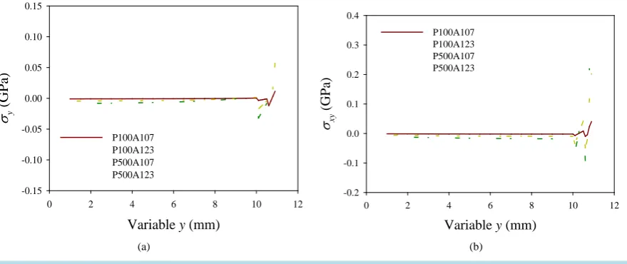
Figure 6(a) and Figure6(b) represent the longitudinal stress distribution profiles and the shear stress distri-bution profiles, respectively. The domain is under the compressive longitudinal stress except the neighborhood of the boundary, and the stress fluctuates near the boundary (Figure 6(a)). The magnitude of the longitudinal stress is getting larger along the increments of the cutting angle and vertical force. Under higher pressure the variation of the cutting angle yields deep effect to the movement of the longitudinal stress.
Variable y (mm)
0 2 4 6 8 10
D
isp
la
ce
me
nt
W
(mm)
-0.035 -0.030 -0.025 -0.020 -0.015 -0.010 -0.005 0.000 0.005
P100A107 P100A123 P500A107 P500A123
Figure 4. Longitudinal displacement distribution profiles.
Top coat
Variable x (mm)
0 20 40 60 80 100 120 140 160 180 200
σx
(GP
a)
-0.25 -0.20 -0.15 -0.10 -0.05 0.00 0.05
P100A107 P100A123 P500A107 P500A123
Bond coat
Variable x (mm)
0 20 40 60 80 100 120 140 160 180 200
σx
(GP
a)
-0.05 -0.04 -0.03 -0.02 -0.01 0.00
P100A107 P100A123 P500A107 P500A123
(a) (b)
Substrate
Variable x (mm)
0 20 40 60 80 100 120 140 160 180 200
σx
(GP
a)
0.000 0.001 0.002 0.003 0.004 0.005 0.006
P100A107 P100A123 P500A107 P500A123
[image:6.595.93.537.262.617.2](c)
Figure 5. Horizontal stress distribution profiles: (a) At the top coat; (b) At bondcoat; (c) At the substrate.
shear stress is so sensitive to the change of cutting angle under high vertical force.
4. Conclusion
Variable y (mm)
0 2 4 6 8 10 12
σy
(GP
a
)
-0.15 -0.10 -0.05 0.00 0.05 0.10 0.15
P100A107 P100A123 P500A107 P500A123
Variable y (mm)
0 2 4 6 8 10 12
σxy
(GP
a)
-0.2 -0.1 0.0 0.1 0.2 0.3 0.4
P100A107 P100A123 P500A107 P500A123
[image:7.595.95.535.87.272.2](a) (b)
Figure 6. Stress distribution profiles: (a) Longitudinal stress; (b) Shear stress.
zontal displacement at the substrate explains well the buffering mechanism of the bond coat. For the longitudinal stress and the shear stress distribution profiles, the variation of cutting angle under high vertical force displays profound influence on the movement implying that the controlling the factors: cutting angle and vertical force are important process.
Acknowledgements
This research was supported by Basic Science Research Program through the National Research Foundation of Korea (NRF) funded by the Ministry of Education (2013R1A1A2059235). This work was supported by the Na-tional Research Foundation of Korea (NRF) grant funded by the Korea government (MSIP) (2011-0030058).
References
[1] Davim, J.P. (2010) Surface Integrity in Machining. Springer, London. http://dx.doi.org/10.1007/978-1-84882-874-2
[2] Denkena, B., Köhler, J. and Mengesha, M.S. (2012) Influence of the Cutting Edge Rounding on the Chip Formation Process: Part 1. Investigation of Material Flow, Process Forces, and Cutting Temperature. Production Engineering, 6, 329-338. http://dx.doi.org/10.1007/s11740-012-0366-x
[3] Hosseinkhani, K. and Ng, E. (2013) Analysis of the Cutting Mechanics under the Influence of Worn Tool Geometry. Procedia CIRP., 14th CIRP Conference on Modeling of Machining Operations (CIRP CMMO), 8, 117-122.
[4] Rodríguez, J., Arrazola, P., Cante, J., Kortabarria, A. and Oliver, J. (2013) A Sensibility Analysis to Geometric and Cutting Conditions Using the Particle Finite Element Method (PFEM). Procedia CIRP., 14th CIRP Conference on Modeling of Machining Operations (CIRP CMMO), 8, 105-110.
[5] de Agustina, B., Bernal, C., Camacho, A.M. and Rubio, E.M. (2013) Experimental Analysis of the Cutting Forces Ob-tained in Dry Turning Processes of UNS A97075 Aluminium Alloys. Procedia Engineering, 63, 694-699.
http://dx.doi.org/10.1016/j.proeng.2013.08.248
[6] Wallbank, J. (1979) Structure of Built-Up Edge Formed in Metal Cutting. Metals Technology, 6, 143-153. http://dx.doi.org/10.1179/030716979803276426
[7] Kümmel, J., Gibmeier, J., Müller, E., Schneider, R., Schulze, V. and Wanner, A. (2014) Detailed Analysis of Micro-structure of Intentionally Formed Built-Up Edges for Improving Wear Behaviour in Dry Metal Cutting Process of Steel. Wear, 311, 21-30.