© 2017, IRJET | Impact Factor value: 5.181 | ISO 9001:2008 Certified Journal
| Page 496
Performance of induction motor at variable voltage using Artificial
Neural Network
Rachna Shingode
Assistant Professor, Dept. of Elect. Engg. , S.G.S.I.T.S., Indore, India
---***---Abstract -
This paper evaluate the performance of a 220V, 50Hz three phase induction motor operating at under voltages of 200V and 210V and over voltages of 230V and 240V respectively. The performance of the motor has been evaluated assuming that the resistance and reactance parameters of the induction motor equivalent circuit specified at the rated 50Hz frequency. The slip, power factor, efficiency decreases with as voltage decreases. Whereas input power increases with decrease in voltage.The ANN can process the information in parallel and distributed manner. Because of these features ANN are being used in solving many problems. Main dictum of this paper is to examine effect of voltage variation on induction motor. These algorithms are implemented and tested using Matlab.Key Words: Induction motor, Under frequency operation,
Variable voltage operation, Performance, Equivalent circuit, ANN
1. INTRODUCTION
The need for ensuring a high degree of service reliability in the operation of modern electric systems cannot be overemphasized. In the early days of power development, complete loss of power supply over prolonged period was the primary concern. However, with the growing use of electric appliances such as refrigerators and electric cookers for domestic purposes and increasing industrial demands, even momentary interruptions have become a matter of concern due to either a serious damage to the equipment or heavy production loss.
Amongst the worst affected consumers apparatus are the single phase fractional horsepower motors used in refrigerators, home freezers and water systems. When the voltage is low the motor draws less current and the current relay may fail to disconnect the starting winding. The current may be too low to operate the overload relay, but may be high enough to damage the starting winding and thus lead to the burn out of the motor. In many large interconnected systems having inherently low rate of frequency decay, low voltage may be more objectionable than low frequency. Consumers find reduction in voltage more objectionable than reduction in frequency. It is essential therefore to provide, besides sufficient generation reserve, sufficient
reactive reserve to maintain satisfactory voltage levels under both normal and emergency conditions. The apparatus normally used for such purposes are synchronous condensers, and shunt capacitor banks [3]. In this paper, the effect of variation of voltage on the performance of induction motor using artificial neural network have been studied.
2. THREE PHASE INDUCTION MOTOR
A polyphase induction motor is a singly excited a.c. machine. Its stator winding is directly connected to a.c. source, where as its rotor winding receive its energy from stator by means of induction (transformer action). Balanced polyphase currents in polyphase winding produces a constant amplitude rotating mmf wave. The stator produced mmf wave and rotor produced mmf wave, both rotate in the air gap in the same direction at synchronous speed. These two mmf wave are thus stationery with respect to each other consequently the development of steady electromagnetic torque is possible at all speeds but not at synchronous speed. The stator and rotor mmf wave of constant amplitude and rotating at synchronous speed. Since run at synchronous speed, it is called asynchronous machine [1, 2].
The performance of the three phase induction motor has been evaluated from the parameters of the equivalent circuit in the usual way. The equivalent circuit parameters R1, R2, X1, X2 and Xφ are assumed to be known at rated voltage and rated frequency. Both the resistance and reactance parameters are calculated at 50Hz frequency. In this paper the equivalent circuit parameters and the friction and, windage losses(FW) are assumed to be known at 50 Hz. Core loss occurs in the stator, but in the rotor at the slip frequency it is practically absent, and is excluded in this analysis.
The mechanical power = (1-S)Pg Where
S=slip
Pg= Air gap power
(1-S)Pg=Output Power +FW
© 2017, IRJET | Impact Factor value: 5.181 | ISO 9001:2008 Certified Journal
| Page 497
Rf = R2 Xφ2/S(R2/S)2+( X2 + Xφ)2
Xf = X2Xφ(X2 + Xφ) + (R2/S)2 Xφ/ ((R2/S)2 + (X2 + Xφ)2) The air gap power
Pg = 3I12 Rf Where
I1 = stator current I1= VLL
√3 ((Rf + R1)2 + ( Xf + X1)2) VLL= Line to line supply voltage
R1 and X1 = Stator resistance and reactance
For a given load on the motor, the slip of the motor has been determined and then the stator current, power factor, synchronous speed, actual speed, power input and efficiency at different voltages have been determined [1]. The parameters R1, R2, X1, X2 and Xφ of the induction motor equivalent circuit at rated frequency are assumed to be known. The sum of the friction and windage loss, FW at the rated frequency is also assumed to be known [1].
(1-S)Pg=output power +FW (1) S=1-(output power + FW)/Pg S=1-(output power + FW)/ 3I12 Rf S=1-(output power + FW)/ 3Rf VLL
((Rf + R1)2 + (Xf+ X1)2) R1 and X1 are neglected, so we get
S=1- (output power + FW) ( R2f+ X2f) V2LL Rf
2.1 Effect of voltage variations on the induction
motor performance
With the induction motor running under full load condition, its stator voltages may fall during peak load periods on the supply system. With advertent voltage variation, supply frequency is assumed to remain constant.
For constant load:
The power transferred from stator to rotor is Pg = E2I2CosѲ2
Electromagnetic torque Te is Te = Pg/ωs = E2I2CosѲ2/ωs
The voltage E2 induced in the rotor phase at standstill, is proportional to the air gap flux Փ
Te = K1ՓI2CosѲ2
For the stator the supply voltage V1 is related with flux Փ by the approximate expression
V1 = √2πfN1ՓKw = K2fՓ
K1 and K2 are proportionality constants
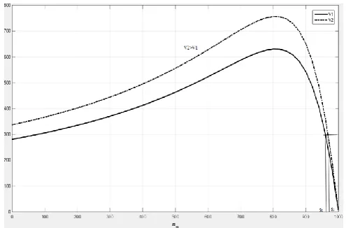
If supply voltage V2 decreases to V1, then torque slip curve for both V2 and V1 as shown in fig.1. This figure revels that for constant load torque, the slip S2 for voltage V2 increases to slip S1 for voltage V1. With increase in slip, rotor power factor also decreases.
CosѲ2 = R2/√ (R22 + (SX2)2)
For voltage V2, the air gap flux Փ is less. Since both Փ and CosѲ2 have decreased, though magnetizing current and a lower operating life. If supply voltage increases, the
[image:2.595.314.562.139.302.2]operating slip decreases by a very small amount. The magnetizing current always increases with increment in supply voltage [2].
Fig.1: Speed Torque characteristics for constant power load
3. ARTIFICIAL NEURAL NETWORK
The artificial neural often called the neural network, is the most Generic form of AI (Artificial Intelligence) for emulating the human thinking process compared to the rule based expert system and fuzzy logic, the cerebral cortex of a human brain is said to contain around 100 billion nerve cells or biological neurons, which are interconnected to form a biological neural network. The memory and intelligence of the human brain and the corresponding thinking process are generated by the action of this neural network. However inferior and the ANN model of the biological nervous system, it tends to solve many important problems. An ANN is particularly suitable for solving pattern recognition and image processing type problems that are difficult to solve by conventional digital computer. Neural Network can also be defined as parameterized computational nonlinear algorithms for numerical data / signal / image processing hardware. These algorithms are either implemented on a general purpose computer or built into a dedicated. Artificial Neural Network is thus information processing system, the elements called as neurons, process the information. The signals are transmitted by means of connection links. The links possess an associated weight, which is multiplied along with the incoming signal (net input) for any typical neural net. The output signal is obtained by applying activations to the net input.
© 2017, IRJET | Impact Factor value: 5.181 | ISO 9001:2008 Certified Journal
| Page 498
The structure of the simple artificial neural network isshown in fig.2 shows a simple artificial neural network with two input neurons (X1, X2) and one output neuron (Y). The inner connected weights are given by W1 & W2.Various inputs to the networks are represented by the mathematical symbol, X(n).
Each of these inputs are multiplied by a connection weights. These weights are represented by W(n). In the simplest case, these products are simply summed, fed through a transfer function to generate a result and then delivered as output. This process tends to physical implementation on a large scale in a small package.
Broadly, the ANN technology has been applied in process control, identification, forecasting, diagnostics, robot vision and financial problems.
Fig.3: Schematic diagram of a typical nerve cell or neuron In general the function of the main element can be given as, Dendrite – Receives signals from other neurons
Soma – Sums of all incoming signals
Axon – When a particular amount of input is received, then the cell fires, it transmit signal through axon to other cell Synapse – It is the junction in dendrites, which influence the signal flow magnitude
3.1 Artificial Neuron
An artificial neuron is a concept whose components a direct analogy with the biological neuron fig.3 shows the structure of the artificial neuron, reminding us of an analog summer-like computation. It is also called neuron, processing element, neuron node or cell. The input signals X1, X2, X3,…Xn are normally continence variables but can also be discrete pulses. Each input signal flows through a gain or weight, called synaptic weight or connection strength whose function is analogous to that of the synaptic junction in biological neuron. The summing node accumulates all the input weighted signal, adds the bias signal b and then passes to the output through the activation function which is usually nonlinear in nature. Mathematically the output expression can be given as
Basic building blocks of artificial neural networks
The basic building blocks of the artificial neuron are 1. Network architecture
2. Setting the weights 3. Activation function
3.1.1 Network Architecture
The arrangement of neurons into layers and a pattern of connection with and in between layer are generally called as the architecture of the network. The neurons with in a layer are found to be fully interconnected.
The number of layer in the network can be defined to be the number of layers of weight interconnected links between the particular slabs of neurons. If two layers of interconnected weights are present, there it is found to have hidden layers. There are various type of network architecture; feed forward, feedback, fully interconnected, competitive network etc.
3.1.2 Setting The Weights
The method of setting value of the weights enables the process of learning of training. The process of modifying the weights in the connection between network layers with the objective of achieving the expected output is called training a network. The internal process that takes place when network is trained is called learning. Generally there are three types training as follows.
1. Supervised training 2. Unsupervised training 3. Reinforcement training
3.1.3 Activation Function
The activation function is used to calculate the output response of a neuron. The sum of the weighted input signal is applied with an activation to obtain the response. For neurons in same layer, same activation function are used. There may be linear as well as nonlinear activation function used in a multilayer network e.g. Identity function, step or threshold function, signum function, and sigmoidal function etc [5].
3.2
Applications of Artificial Neural Network
The ANN have found diverse successful applications in computers vision, images/signal processing, speech/characters recognition, expert systems, medical images analysis, remote sensing, industrial inspection and scientific exploration. In a superficial way, the domain of the applications of the artificial neural networks can be divided into the following categories:© 2017, IRJET | Impact Factor value: 5.181 | ISO 9001:2008 Certified Journal
| Page 499
b) Grouping: Also denominated non classification, because there is no a predefined structure of classes. The networks explore the objects presented and generate groups of elements that follow certain similarity criteria.
c) Approximation of functions: with base in a group of pairs (ordered pairs of entry/exit) generate by an unknown function of the network its internal parameters to produce exists that implicitly corresponds to the approximation of the function
d) Prediction: Predicting the behavior of an event which depends from the time, with base in a group of values that are obtained from different moments.
e) Optimization: A great variety of problems in Math, Science, Medicine and Engineering can be focused as problems where is required to determine a solution that accomplishes with a group of restrictions and diminishes or maximizes an objective function.
f) Oil Exploration: Though vector processing, Neural Network can exploratory a new oil mine according the distance between oil explorers. It also depends upon external parameters about the environment.
g) Simulation: Simulation is an important application of neural network for creating similar characteristics as of actual machine of multiple devices. By using CAD, we can create the model of automobiles as well as other.
For such applications are successful solution form a classic perspective, however in most of the cases they are only valid in restricted environments and present little flexibility out of its domain. The ANN gives alternatives which give flexible solutions in a great domain.
Algorithm for identification of induction motor
parameter using artificial neural network
The network is trained in following steps: 1. Enhanced input set is assumed as [V] = X
2. Weight W1 - W3 are selected as low random numbers 3. Set iteration count K=1
4. Present a training instance to the network
5. The numerical values of the slip, power factor, input power & efficiency at a constant frequency 50 Hz and five voltages are obtained from table1
6. Obtain error for slip, power factor, input power & efficiency
δ1= ηt - ηc δ2= Pft - Pfc δ1= St - Sc δ1= Wit - Wic
7. Update the weight by δ- rules as follow ΔW1=ηO1(1-O1)[δ1V11+ δ1V21+ δ1V31+ δ1V41]X ΔW2=ηO2(1-O2)[δ1V12+ δ1V22+ δ1V32+ δ1V42]X ΔW3=ηO3(1-O3)[δ1V13+ δ1V32+ δ1V33+ δ1V43]X η is learning rate (0<η<1)
8. If all the training instances have been presented, then go to step 9 otherwise
repeat from step 4
9. Calculate error using final weights as follows NT
E =Ʃ[(ηtn - ηcn)2+( Pftn - Pfcn)2+( Stn - Scn)2+( Witn - Wicn)2] n=1
ηtn, Pftn, Stn and Witn represent target value of both the parameter corresponding to Nth training instances. ηcn, Pfcn, Scn and Wicn represents calculated parameter using weights NT denotes the total number of training instances.
10. If E<=τ (tolerance) then stop
Otherwise K=K+1 and then repeat from step 4
The process of iteration is terminated if (E<= τ) or a maximum number of iterations have been executed. Once the network is trained validation of the network established with the help of testing instances other then used in training instances.
Induction Motor Model Simulation Using Back
Propagation Based ANN (BPANN)
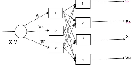
BPANN has been used for induction motor modelling. Here two layer have been used one of it is hidden layer. Neurons in the hidden layers are assumed to be sigmoidal and those in output layer are assumed here as linear [6]. The structure of the networks is shown in fig.4.
Linear neuron in the output layer is 4 in no. One for efficiency, second for power factor, third for slip and forth for input power. These four parameters are governed by following equation output of each neuron in the hidden layer is given by
Om = 1/(1+e-(netm))
netm = WmX m=1,2,3………..NH
NH denotes total neurons in hidden layer
NH ηc = Ʃ V1joj j=1
NH Pfc = Ʃ V2joj j=1
NH Sc =
Ʃ
V3joj j=1 NH Wic = Ʃ V4joj j=1In terms weights finally motor parameters can be written as
NH
© 2017, IRJET | Impact Factor value: 5.181 | ISO 9001:2008 Certified Journal
| Page 500
NHPfc = Ʃ V2j/(1+e- WjX) j=1
NH
Sc =
Ʃ
V3j/(1+e- WjX) j=1NH
Wic = Ʃ V4j/(1+e- WjX) j=1
Weight Wj & Vji are obtained by the training algorithm is based on back propagation training algorithm is given in many standard text books and references hence not
reproduced here.
Fig.4:Architecture of BPANN for motor
Table 1
-
Target values and calculated values by ANN at 50 Hz frequency4. Result
Training and test instance were obtained in the laboratory a three phase 220V, 10 HP, 6 Pole, 50 Hz induction motor is considered for the study. Results of the analytical work show that given output of 7 HP. The slip and the power factor both increased as the voltage is reduced at the given frequency. The actual speed of the motor reduced at the given frequency, however as the voltage is reduced. The starter current, input power efficiency shows a nonlinear behavior with a change in voltage at given frequency. The starter
current and input power decreased when the voltage raised from 200V to 210V, but their values start increasing as the voltage is raised farther up to 240V. The numerical values of the slip, starter current, power factor, input power and efficiency at a motor output of 7 HP are obtained at a constant frequency and 5 variable voltage from table 1[3]. The input power usually taken in p.u. (6811 as base value) and efficiency represent in percentage. The network is trained in such a way that if the frequency is constant and voltage very from 200V to 240V then the network gives the slip, power factor, efficiency, input power. Learning rate η was taken as 0.08. Weights of the trained were obtained as follows:
W1 = -0.900050 W2 = 0.251598 W3 = 0.835136
[image:5.595.38.249.303.409.2]Table 1 shows target values efficiency, power factor, slip and input power and the values obtained by ANN. The % error in all cases is less than 3%. Percentage errors are shown in table as εη, εpf, εs, εwi for each cases for efficiency, power factor, slip and input power respectively. Similarly motor model in the form as shown in fig.4 was obtained by training the network using back propagation algorithm. Three neurons were selected in hidden layers. Learning rate was selected as η=0.08 motor model was identified in the form of equation Δ weights after training the network were obtained as follows
V11 = 2.672625, V12 = 0.733129, V13 = 0.599415 V21 =1.511477, V22 = 0.971753, V23 = 0.216796 V31 = 0.129558, V32 =-0.037137, V33 = 0.003277 V41 = -2.119334, V42 = 0.933904, V43 = 1.561453 W1 = -0.900050, W2 = 0.251598, W3 = 0.835136
5. CONCLUSIONS
The performance of a three phase induction motor at different voltage and constant frequency has been studied in this paper and the numerical results of the slip, power factor, input power and efficiency are given. The equivalent circuit parameters of the induction motor are assumed to very proportionality with their values at the rated frequency. An application of ANN has been introduced to represent induction motor model accurately. It has been stressed here that the value of slip, efficiency, input power and power factor can be achieved by setting the proper size of network. Such flexibility does not seem to appear in traditional motor model. This justify the use of ANN for the motor modelling to given the performance of the induction motor under variable voltage at constant frequency and introducing application to beginners for educational purpose. The work in this paper may be extended as ANN based under variable voltage and variable frequency.
REFERENCES
© 2017, IRJET | Impact Factor value: 5.181 | ISO 9001:2008 Certified Journal
| Page 501
[2] Dr. P.S. Bhimra, Electrical machines, Khanna Publishers2001.
[3] Prof. C.S. Indulkar “ Performance of induction motor under variable voltage and variable frequency” Journal of electrical machines, Vol. 80, Feb. 2000, PP 155-157. Person Education, 2004.
[4] B. K. Bose, Modern power electronics and AC device, Person Education, 2004.
[5] S. Haykin ‘Neural Network: A comprehensive foundation’ Second Ed., Person Education, 2003.
[6] L. M. Fu. ‘Neural Network in computer intelligence’ Mc- Graw-Hills Ins. 1994.