© 2018, IRJET | Impact Factor value: 6.171 | ISO 9001:2008 Certified Journal | Page 3326
OPTO-MECHANICAL DESIGN OF ALL ALUMINIUM RC TELESCOPE
Saurabh Mehta
1, Chirag Dewan
21
P.G Student (CAD/CAM), Department of Mechanical Engineering, Chandubhai S Patel Institute of Technology,
CHARUSAT University, Changa, Gujarat
2
Group Director, Optical Payload Mechanical Group, Space Application Center, ISRO, Ahmedabad, Gujarat
---***---Abstract -
Satellite images serve a most essential part inapplications running from ecological protection, calamitous event and agriculture to intelligence and security. For high resolution images, we need to build substantial and heavy telescopes. The expenses of building large and heavy telescope system are huge, which brings high image costs. With large aperture mirror, telescope can be designed that achieve high resolutions images. This project presents the optomechanical design of telescope which has a large aperture primary mirror. The paper describes the mechanical and optical aspects of telescope. The Finite element analysis is performed and results are verified by vibration test.
Key Words: Optomechanical design, Space telescope, RC
telescope, Metallic mirrors, Finite element analysis (FEA), Rapidly solidified aluminium (RSA), All aluminium telescope, Vibration test.
1.Introduction
[image:1.595.336.531.625.684.2]In this paper, a conceptual design of Ritchey–Chrétien telescope is presented. RC configuration utilizes concave hyperboloid primary mirror and convex hyperboloid secondary mirror. This limits a portion of the most noticeable aberrations found in different telescopes and takes into consideration extensive field of view (FOV) that is generally sharp to the edge. RCT is a particular variation of the Cassegrain telescope. It eliminates off axis optical aberrations by using hyperbolic PM and SM. The RCT has a more extensive FOV free of optical aberrations contrasted with conventional reflecting telescope. The mirror was made from Rapidly Solidified Aluminium (RSA-6061T6) which has high density fine and homogeneous grain structure. All the telescope components were designed in Creo Parametric 3.0. Finite element analysis was performed and results were verified by vibration test. Configuration of RC telescope is shown in fig. 1.
Fig 1. RC telescope configuration
2. Literature Review
[1] Thomas & Tony explained Zerodur as highest quality level material for applications which require great dimensional steadiness. It can be light weighted to 85% to 90% level for use in telescopes. It has low CTE and surface roughness can be accomplished under 1 nm RMS. Outrageous lightweight Zerodur mirrors have been delivered unequivocally to give architects of spaceborne missions another fiscally keen, elective for execution of medium and immense Optical Telescope Assemblies (OTA). Zerodur mirrors used in in space with more than 30-year legacy. Zerodur properties will affirm utility of this approach for future telescopes.
[2] John & Daniel presented Aluminium mirrors have benefits of less cost, shorter manufacture time, more tough mounting, enhanced warm execution and same material athermalization compared to glass mirrors. To a great degree lightweight sandwich mirrors can be made which are lightweighted contrasted with glass mirrors. Aluminum is reasonable option for glass mirrors applications like airborne and satellite systems. Specific stiffness is same as glass mirror. The cost of presented mirror is 1.57 to 2 times lower than glass mirror.
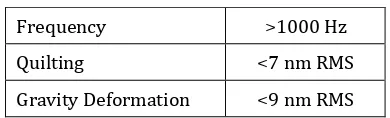
[image:1.595.45.281.643.725.2][3] Haeng-Bok & Richard presented the conceptual design for Primary Mirror (PM) and metering structure. Optomechanical assembly must stay in alignment after launch and during operation. For high resolution and wide FOV space telescope require large primary mirror aperture. Light weighted PM with bigger opening used to diminish launch cost. Deformation due to gravity relies on distance between supporting points to center of gravity. Design criteria for SiC mirror is shown in table 1.
Table 1. Design criteria for SiC mirror
Frequency >1000 Hz Quilting <7 nm RMS Gravity Deformation <9 nm RMS
© 2018, IRJET | Impact Factor value: 6.171 | ISO 9001:2008 Certified Journal | Page 3327 Metering structure for mirror assembly requires good
dimensional steadiness, high stiffness and least barrier. Properties of SiC make it appropriate material for design. Four following configurations (fig. 2) are selected for link among base plate and SM assembly:
Fig. 2 Tripod, hexapod, octopod and cylinder metering structure
[image:2.595.375.483.128.284.2][4] Zhang et al. described 3 Bipod structure for supporting mirror improves surface accuracy under working conditions and have good dynamic characteristics. Simulation analysis by PATRAN and experimental verification by ZYGO interferometer software results show that bipod support structure can keep the reflector in good shape under static and thermodynamic environments. Error of analysis is 1% compared with theoretical calculation which states that system has good kinetic properties even after reducing radial stiffness. Bipod structure (fig. 3) also has good release effect on assembly stress.
Fig. 3 Flexible lens holder
[5] For microsatellite application, Xuegui et al. develop deployable telescopes. PM and SM were made of Zerodur. This telescope is lightweighted, having compact launch volume and less costly.
Paper presents 3 parts.
(A) Telescope optics: A Ritchey–Chrétien configuration with 300 mm diameter was modeled with ZEMAX.
(B) Telescope support structure: The primary mirror supported with super invar bipods. Telescope support plate was made from CFRP.
(C) Metering structure: The structure linking telescope support plate and secondary mirror assembly made up of 6 super invar brackets and 6 tape springs. (fig. 4)
FEM was used to analyze telescope structure and it shows that tape springs has enough stiffness to ensure dynamical
[image:2.595.39.287.148.227.2]environment of satellite in orbit. First modal frequency of telescope is about 64 Hz and lowest buckling load factor is 13.3 under 1 G load in lateral direction.
Fig. 4 3D structural model for deployable telescope
3. Design and analysis of telescope
[image:2.595.335.529.366.516.2]Design process is shown in below fig. 5.
Fig. 5 Design process
It is an ‘all aluminum’ RC telescope. All the parts are made from aluminum alloy 6061T6. Especially mirror was made from Rapidly solidified aluminum-6061T6. Below table 2 shows the components of telescope. All components are modelled using Creo Parametric 3.0.
Table 2. Components of RC telescope
Category RC Telescope
Optical parts Primary mirror Secondary mirror Mechanical parts PM baffle
SM baffle
[image:2.595.73.250.408.507.2]© 2018, IRJET | Impact Factor value: 6.171 | ISO 9001:2008 Certified Journal | Page 3328 3.1 Primary mirror & secondary mirror
[image:3.595.316.554.104.366.2]Primary and secondary mirror were fabricated from Rapidly Solidified Aluminum 6061T6 grade material. RSA enables fabricator to achieve surface finish required as mirror. The fabrication was done by Single Point Diamond Turning (SPDT) tool. Fig. 6 shows the CAD model of PM and SM. Two types of analysis were done on mirror. Wavefront error of mirror was checked by using Zernike polynomials coded in MATLAB.
Fig. 6 CAD model of PM and SM
[image:3.595.39.283.215.338.2] In performance analysis, the optical properties of mirror under gravity deformation and assembly load was checked. For this analysis, we have used Creo Simulate 3.0 and MATLAB. Results of this analysis are shown in below table 3 & 4.
Table 3. PM under 1 G and 50 μ Undulation
Parameters Gravity load 1 G Undulation 50 μ RMS of Fig. 0.0067706 0.0081146
Piston 0.0170933 5.2697617
Tilt about Y 1.3221567 17.9590841 Tilt about X -0.0081818 0.0021724
Focus 0.0002006 0.0014891
Astigmatism 0
deg 0.0076171 0.0186976
Astigmatism
45 deg 0.0000874 0.0002505
Coma X 0.0094252 0.0013032
Coma Y -0.0000448 -0.0003665
Spherical -0.000354 -0.0021052
Trefoil X -0.0000455 0.0000413
[image:3.595.315.558.415.521.2]Trefoil Y 0.0000099 0.0000126
Table 4. SM under 1 G and 50 μ Undulation
Parameters Gravity load 1 G Undulation 50 μ RMS of Fig. 0.0001339 0.002245
Piston 0.0075603 5.283418
Tilt about Y 0.0098197 -0.0558 Tilt about X 0.5172088 24.24041
Focus -0.0000011 -1E-05
Astigmatism 0
deg 0.0002598 -0.00541
Astigmatism
45 deg -0.0000052 3.78E-05
Coma X 0 -9.7E-06
Coma Y 0.0001178 3.05E-05
Spherical 0.0000005 7.1E-06
Trefoil X 0.0000006 -1E-05
Trefoil Y 0.000003 1.48E-05
Stress for undulation in PM was 4.5 MPa and 17 MPa for SM (fig. 7).
Fig. 7 Maximum Undulation stress for a) PM and b) SM
In survivability analysis, the stresses of mirror under 55 G load was measured (fig. 8).
For PM, maximum Von-Mises stress was 100 MPa in X & Y direction and in Z direction it was 150 MPa, which is below our design criteria. (155 MPa)
[image:3.595.41.286.459.724.2] [image:3.595.310.569.630.740.2]© 2018, IRJET | Impact Factor value: 6.171 | ISO 9001:2008 Certified Journal | Page 3329 For SM, maximum Von-Mises stress was 34 MPa in X, 42 MPa
[image:4.595.305.560.47.205.2]in Y direction and 45 MPa in Z direction which is below our design criteria. (50 MPa) (fig. 9)
Fig. 9 Results of steady state load 55 G for SM
3.2 Baffle design
Fig. 10 a) PM baffle & b) SM baffle
3.3 Metering structure
It consists of the metering cylinder and the spider arm assembly (fig. 11). Primary mirror is supported on lower ring and secondary mirror is mounted on spider of upper ring.
Fig. 11 Isometric View of Metering Structure
3.4 Optical bench
[image:4.595.35.303.121.235.2]Optical bench supports metering structure & primary mirror on one side and FCO & Detector assembly on other side. Isometric view of optical bench is shown in fig. 12.
Fig. 12 Isometric View of Optical bench
3.5 Supporting Structure
[image:4.595.339.525.299.452.2]It consists of Bracket and cone structure made up of aluminium. It will support full assembly. Fig. 13 Shows isometric view of support structure.
Fig. 13 Isometric view of support structure
3.6 Assembly of telescope
After modelling of all the components, the assembly of telescope was done as shown in fig. 14.
Fig.14 Assembly of telescope
Mesh generation
Mesh was generated by AUTOGEM function in Creo simulate 3.0 as shown in fig. 15.
[image:4.595.41.286.322.427.2] [image:4.595.90.235.536.666.2] [image:4.595.328.539.538.679.2]© 2018, IRJET | Impact Factor value: 6.171 | ISO 9001:2008 Certified Journal | Page 3330 Fig. 15 Mesh generation
Modal analysis of full assembly is done to find natural frequency of assembly (fig. 16). Assembly was constrained at 32 lugs of supporting structure.
[image:5.595.37.289.288.435.2]The first modal frequency was 115 Hz.
Fig. 16 First mode of telescope
The second modal frequency was 141.2 Hz as shown in fig. 17.
Fig. 17 Second mode of telescope
4. Results and Evaluation
[image:5.595.308.558.384.539.2]The force limited vibration was performed on telescope. Telescope was mounted on shaker plate by means of interface plate (fig. 18). Four force links were used for measuring and controlling force during vibration testing. 4 accelerometers were placed at top of optical bench, optical bench and bracket interface, secondary mirror & cylinder end.
Fig. 18 Telescope mounted on shaker plate
Vibration test was performed for all axis. In first mode maximum displacement occurs at the cylinder end (Fig 16). We checked the response of cylinder accelerometer. From graph (fig. 19) we can see that during vibration test, the first mode appeared at 115.9 Hz, which is closest to 115 Hz. We have checked the response of sensor placed on top of optical bench. It had also first mode frequency was 115.9 Hz in fig. 20.
Fig. 19 Vibration response of accelerometer placed at cylinder end
[image:5.595.36.289.489.634.2] [image:5.595.307.556.552.733.2]© 2018, IRJET | Impact Factor value: 6.171 | ISO 9001:2008 Certified Journal | Page 3331 In second mode maximum displacement occurs at cylinder
end and secondary mirror assembly. We checked the response of sensor placed near secondary mirror. From below graph (fig. 21) we can see that during vibration test, the second mode appears at 148.6 Hz, which is closest to 141.2 Hz.
Fig. 21 Vibration response of accelerometer placed at secondary mirror
[image:6.595.36.288.163.337.2]5. Comparison of Results
Table 5. Comparison of results
Mode Theoretical results (Frequency)
Experimental results (Frequency)
Error
1 115 115.9 0.78 %
2 141.2 148.6 5.24%
6. Conclusion
Various types of telescope configurations were studied in detail. Their constructions, materials and manufacturing processes being used for space telescope studied theoretically. Here, special material known as Rapidly Solidified Aluminium(RSA)-6061T6 had been chosen for mirror material. Since, it had to be fabricated by Single Point Diamond turning tool, a special design and analysis had been carried out to suit machining process and stress-free mounting. Lightweight RC telescope was designed and structural modal was generated. Design had been validated by vibration testing. Experimental and theoretical results were matching very closely. Testing had been done successfully as per environmental space requirement.
REFERENCES
[1] Tony Hull, Thomas Westerhoff, "Lightweight ZERODUR:
a cost-effective thermally stable approach to both large and small spaceborne telescopes", Proc. SPIE 9070, Infrared Technology and Applications XL, 90702D (24 June 2014); doi: 10.1117/12.2050997.
[2] Daniel Vukobratovich, John P. Schaefer, "Large stable
aluminum optics for aerospace applications", Proc. SPIE 8125, Optomechanics 2011: Innovations and Solutions, 81250T (24 September 2011); doi: 10.1117/12.892039.
[3] Haeng-Bok Lee, Richard G. Cobb, "Design of lightweight
primary mirror and metering structure for spaceborne telescope", Proc. SPIE 6049, Optomechatronic Sensors and Instrumentation, 60490P (6 December 2005); doi: 10.1117/12.648009.
[4] Zhang, L.-M & Wang, F.-G & An, Q.-C & Yang, F & Wang, Z.
(2015) “Application of Bipod to supporting structure of minitype reflector” Guangxue Jingmi Gongcheng/Optics and Precision Engineering 23, 438-443. https://doi.org/10.3788/OPE.20152302.0438
[5] Xuegui Feng, Chuang Li, Guorui Ren, "Medium-sized