ABSTRACT
This paper presents a comparative assessment of modern and intelligent controllers based on time response specification performance for a yaw control of an aircraft system. The dynamic modeling of yaw control system is performed and an autopilot that controls the yaw angle of an aircraft is designed using two controller design methods. The mathematical model of the system is derived by substituting the known parameters of a standard aircraft in standard equations. The transfer function for yaw control surface, i.e. rudder, is derived and two separate controllers,Linear Quadratic Controller (LQR) and Fuzzy Logic Controller (FLC) are designed for controlling the yaw angle. The effectiveness of each controllers are tested and verified using Matlab/Simulink platform. It is found from simulation, LQR controller give the best performance compared to fuzzy logic controller
.
General Terms
Fuzzy Logic Controller, LQR Controller, Yaw, Rudder,
Keywords
Aircraft; Flight control, Lateral dynamics; LQR; Fuzzy logic.
1.
INTRODUCTION
Today’s aircraft designs rely heavily on automaticcontrol system to monitor and control many of aircraft’s subsystems. The development of automatic control system has played an important role in the growth of civil and military aviation.The architecture of the flight control system, essential for all flight operations, has significantly changed throughout the years. Soon after the first flights, articulated surfaces were introduced for basic control, operated by the pilot through a system of cables and pulleys. This technique survived for decades and is now still used for small airplanes. The introduction of larger airplanes and the increase of flight envelopes made the muscular effort of the pilot, in many conditions, not sufficient to control the aerodynamic moments consequent to the surface deflection. The first solution to this problem was the introduction of aerodynamic balances and tabs, but further grow of the aircraft sizes and flight enveolpes brought to the need of powered systems to control the articulated aerodynamic surfaces. Modern aircraft include a variety of automatic control system that aids the flight crew in navigation, flight management and augmenting the stability characteristic of the airplane.Theautopilot is an element within the flight control system. Designing an autopilot requires control system theory background and knowledge of stability derivatives at different altitudes and Mach numbers for a given airplane [3..The number and type of aerodynamic surfaces to be controlled changes with aircraft category. Aircraft have a number of different control surfaces: the
basically obtained by deflection of elevators, ailerons and rudder (and combinations of them).Yaw is controlled by the rudder. The pilot moves the rudder sideways and the necessary yaw angle is obtainedIn this paper, the control system design for yaw control is presented. A modern controller (LQR) and intelligent fuzzy logic controller (FLC) is developed for control the yaw of an aircraft system. Performance of both control strategy with respect to the yaw angle and yaw rate is examined. Comparison of both controllers is done and their performance is verified.
2. MODELING OF YAW CONTROL
SYSYEM
[image:1.595.324.570.484.667.2]Two types of dynamical equations are present for an aircraft. The lateral dynamic equations of motion, which represents the dynamics of aircraft with respect to lateral axis and longitudinal dynamic equations of motion which represents the aircraft’s dynamics with repect to longitudinal axis. Lateral dynamics includes yaw, roll and sideslip motions of aircraft. Pitching motion comes under longitudinal dynamics. In this paper, control of yaw angle of aircraft, when it performs yawing motion is explained. The controlsurfaces of aircraft is shown in Fig. 1.
Figure 1.Yaw ,Roll& Pitch motion of Aircraft [10].
The forces, moments and velocity components in the body fixed frame of an aircraft system are shown in Fig. 2 where L, M and N represent the aerodynamic moment components; the term p, q and r represent the angular rates components of roll, pitch and yaw axis and the term u, v and wrepresent the velocity components of roll, pitch and yawaxis.
Aircraft Yaw Control System using LQR and
Fuzzy Logic Controller
Vishnu G Nair
Department of Aeronautical & Automobile Engineering, Manipal Institute of Technology
Manipal, India-576104
Dileep M V
Department of Instrumentation & Control Engineering, Manipal Institute of Technology
Manipal, India-576104
V I George
Department of Instrumentation & Control Engineering, Manipal Institute of Technology
Manipal, India-576104
Figure 2. Definition of forces, moments and velocity components in a body fixed frame [1].
For deriving the lateral equations we assumed that the aircraft is in steady cruise with constant altitude and velocity.Also it is assumed that change in pitch angle does not change the speed of aircraft and the reference flight conditions are symmetric with propulsive forces constant. Therefore,
𝑣 = 𝑝 = 𝑞 = 𝑟 = 𝜑 = 𝜓 = 0(1)
𝑌 + 𝑚𝑔𝐶𝜃𝑆𝜃 = 𝑚(𝑑𝑣𝑑𝑡 + 𝑟𝑢 − 𝑝𝑤) (2)
𝐿 = 𝐼𝑋𝑑𝑝𝑑𝑡 − 𝐼𝑋𝑧𝑑𝑟𝑑𝑡 + 𝑞𝑟 𝐼𝑧− 𝐼𝑦 − 𝐼𝑋𝑧𝑝𝑞 (3)
𝑁 = −𝐼𝑋𝑍𝑑𝑝𝑑𝑡+ 𝐼𝑍𝑑𝑟𝑑𝑡 + 𝑝𝑞 𝐼𝑦− 𝐼𝑥 − 𝐼𝑋𝑧𝑞𝑟(4)
The equations are linearized using small-disturbance theory by replacing all the variables in equations (2),(3) and(4) with a reference value plus a small disturbance. See equation (5)
𝑢 = 𝑢𝑜+ 𝛥𝑢 ;𝑣 = 𝑣𝑜+ 𝛥𝑣;𝑤 = 𝑤𝑜+ 𝛥𝑤
𝑝 = 𝑝𝑜+ 𝛥𝑝; 𝑞 = 𝑞𝑜+ 𝛥𝑞; 𝑌 = 𝑌𝑜+ 𝛥𝑌
𝑟 = 𝑟𝑜+ 𝛥𝑟; 𝐿 = 𝐿𝑜+ 𝛥𝐿; 𝑀 = 𝑀𝑜+ 𝛥𝑀
𝛿 = 𝛿0+ 𝛥𝛿 (5)
Using the above made assumptions, the equations (2),(3) and(4) are linearized.The equations (6),(7) and (8) represents the linearized form, see [1].
𝑑
𝑑𝑡− 𝑌𝑉 𝛥𝑣 − 𝑌𝑃𝛥𝑝 + 𝑢0− 𝑌𝑟 𝛥𝑟 − 𝑔𝑐𝑜𝑠𝜃0 𝛥𝜙 = 𝑌𝛿𝑟𝛥𝛿𝑟 (6)
−𝐿𝑉𝛥𝑣 +
𝑑
𝑑𝑡− 𝐿𝑃 𝛥𝑝 − 𝐼𝑋𝑍
𝐼𝑋
𝑑
𝑑𝑡+ 𝐿𝑟 𝛥𝑟
= 𝐿𝛿𝑎𝛥𝛿𝑎+ 𝐿𝛿𝑟𝛥𝛿𝑟 (7)
−𝑁𝑉𝛥𝑣 +
𝑑
𝑑𝑡− 𝑁𝑟 𝛥𝑟 − 𝐼𝑋𝑍
𝐼𝑍
𝑑
𝑑𝑡+ 𝑁𝑃 𝛥𝑝
= 𝑁𝛿𝑎𝛥𝛿𝑎+ 𝑁𝛿𝑟𝛥𝛿𝑟 (8)
The lateral directional equations of motion consist of the side force, rolling moment and yawing moment equations of motion. In this paper we are taking sideslip angle Δβ instead of the side velocity Δv. These two quantities are related to each other in the following way;[3]
𝛥𝛽 ≈ tan−1𝛥𝑣
𝑢0 =
𝛥𝑣
𝑢0 (9) Lateral equations of motion in state space form is shown in equation (10) 𝛥𝛽′ 𝛥𝑝′ 𝛥𝑟′ 𝛥𝜙′ = 𝑌𝛽 𝑢0 𝑌𝑃
𝑢0 −(1 −
𝑌𝑟 𝑢0)
𝑔𝑐𝑜𝑠 𝜃0 𝑢0
𝐿𝛽 𝐿𝑃 𝐿𝑟 0
𝑁𝛽 𝑁𝑃 𝑁𝑟 0
0 1 0 0
𝛥𝛽 𝛥𝑝 𝛥𝑟 𝛥𝜙
+
0 𝑌𝑈𝛿𝑎0
𝐿𝛿𝑎 𝐿𝛿𝑟
𝑁𝛿𝑎 𝑁𝛿𝑎
0 0
𝛥𝛿𝑎
𝛥𝛿𝑟 (10)
[image:2.595.316.542.219.329.2]For this system, the input will be the aileron deflection angle and the output will be the pitch angle. In this study, the data from NAVION Transport [1] is used in system analysis and modeling. The lateral directional derivatives stability parameters for this airplane are given in Table I. The values are taken directly from reference [3], as these are standard data of the NAVION aircraft.
Table 1. The lateral directional derivatives stability parameters [3] General Aviation Airplane: NAVION Y-Force Derivatives Yawing Moment Derivatives Rolling Moment Derivatives Pitching Velocities
𝑌𝑉= 0.254 𝑁𝑣= 0.025 𝐿𝑣= −0.091
Side Slip Angle
𝑌𝛽
= −44.665
𝑁𝛽= 4.549 𝐿𝛽 = −15.969
Rolling Rate
𝑌𝑃= 0 𝑁𝑃
= −0.349 𝐿𝑃= −8.395
Yawing Rate
𝑌𝑟= 0 𝑁𝑟= −0.76 𝐿𝑟= 2.19
Rudder Deflection
𝑌𝛿𝑟
= 12.433 𝑁= −4.613𝛿𝑟 𝐿𝛿𝑟= 23.09
Aileron Deflection
𝑌𝛿𝑎= 0 𝑁𝛿𝑎
= −0.224 𝐿= −28.916𝛿𝑎
𝛥𝛽′ 𝛥𝑝′ 𝛥𝑟′ 𝛥𝜙′
=
−0.254 0 −1 0.183
−15.969 −8.395 2.19 0
4.549 −0.349 −0.76 0
0 1 0 0
𝛥𝛽 𝛥𝑝 𝛥𝑟 𝛥𝜙
+
0 23.09 −4.613
0
𝛥𝛿𝑟 (11)
Transfer function from rudder deflection angle to yawangle is given by equation (12)
𝛥𝜙 (𝑠)
𝛥𝛿𝑟(𝑠)
=
−4.6130 𝑆3−47.9562𝑆2−11.8833 𝑆+5.7410
𝑆4+9.4090𝑆3+14.0189𝑆2+48.4991 𝑆+0.3979
(12)
3. DESIGN PROCESS OF PROPOSED
CONTROLLER
Linear Quadratic Regulator (LQR) and Fuzzy Logic Controller (FLC) are proposed for the yaw control system and in this section; these controllers are described in detail
.
3.1 Linear Quadratic Regulator (LQR)
Linear quadratic regulator (LQR) is a method in modern control theory and it is an alternative and very powerful method for flight control system designing. The method is based on the manipulation of the equations of motion in state space form and makes full use of the appropriate computational tools in the analytical process [6]. The state and output matrix equations describing the lateral directional equations of motion can be written as the following equation.[3]𝑥’(𝑡) = 𝐴𝑥 𝑡 + 𝐵 𝑢 𝑡 𝑦 𝑡 = 𝐶𝑥 𝑡 + 𝐷𝑢 𝑡 (13)
The feedback gain is a matrix K of the optimal control vector
𝐾 = [𝐾𝛽𝐾𝑃 𝐾𝑟 𝐾𝜙]
𝑢 𝑡 = −𝐾 𝑥 𝑡 + 𝛥𝛿𝑎𝑁 (14)
So as to minimize the performance index
𝐽 = 𝑥ἀ 𝑇𝑄𝑥 + 𝑢𝑇𝑅𝑢 𝑑𝑡
0 (15)
Where Q is state-cost matrix and R is performance indexmatrix. For this study, R=1 and 𝑄 = 𝐶𝑇𝐶where C is the matrix from state equation (13) and 𝐶𝑇 is the matrix transpose of C.[3]. For designing LQR controller, the value of the feedback gain matrix, K, must be determined. Matlab is used to determine the values of K by using the lqr command.
K=[-0.0396 0.0501 -0.7296 0.2886] values are obtained as the weighting factor equals 75. To obtain the desired output we must use a feed-forward scaling factor called N. Because, the full-state feedback system does not compare the output to the reference, it compares all states multiplied by the feedback gain matrix to the reference [5]..The scaling factor N is obtained from Matlab .In this case, N=-3.2376 is determined.
3.2 Fuzzy Logic Controller (FLC)
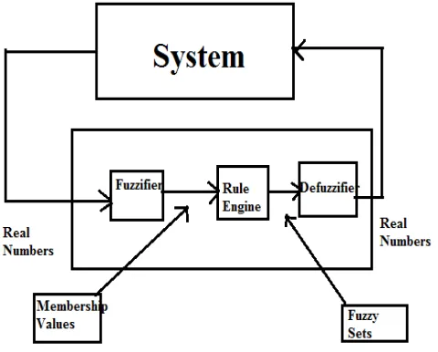
[image:3.595.310.550.477.670.2]The concept of Fuzzy Logic Controller (FLC) was conceived by LotfiZadeh, a professor at the University of California at Berkley, and presented not as a control methodology, but as a way of processing data by allowing partial set membership rather than crisp set membership or non-membership. This approach to set theory was not applied to control systems until the 70's due to insufficient small-computer capability prior to that time. Professor Zadeh reasoned that people do not require precise, numerical information input, and yet they are capable of highly adaptive control. If feedback controllers could be programmed to accept noisy, imprecise input, they would be much more effective and perhaps easier to implement. In this context, FLC is a problem-solving control system methodology that lends itself to implementation in systems ranging from simple, small, embedded micro-controllers to large, networked, multi-channel PC or workstation-based data acquisition and control systems. It can be implemented in hardware, software, or a combination of both. FLC provides a simple way to arrive at a definite conclusion based upon vague, ambiguous, imprecise, noisy, or missing input information. FLC's approach to control problems mimics how a person would make decisions, only much faster. When idea of fuzzy logic is applied to control, it is generally called as ' fuzzy control. Fuzzy control is the first ever applicationknown to which fuzzy logic is applied. The fuzzy controller is composed of four elements. These are fuzzification, rule base, inference mechanism and defuzzification. A block diagram of a fuzzy control system is shown in Fig. 3
Figure 3. The basic structure of fuzzy logic based controlle
The crisp inputs error and change in error are converted to fuzzy membership value on the fuzzy subsets negative big
Error (Z): Small Positive Error (SP): Small Positive Error (P) Big Positive Error (BP).
Fig 4 Error membership functions
[image:4.595.330.549.176.315.2]The “Rate Of Error” input, which represents the rate of the error input, consists of five membership functions. Big Negative (BN)Small Negative (NE): Zero Acceleration (ZR): Small Positive (PE): Big Positive (BP)
Figure 5 Rate of error membership functions.
[image:4.595.56.278.341.496.2]The output of the system consists of seven membership functions as:-Big Negative Angle (BNT),Normal Negative Angle (NNT),Negative Angle (NT),Zero Thrust (ZT): Positive Angle (PT):,Normal Positive Angle (NPT),Big Positive Angle (BPT)
Fig 6 output membership functions
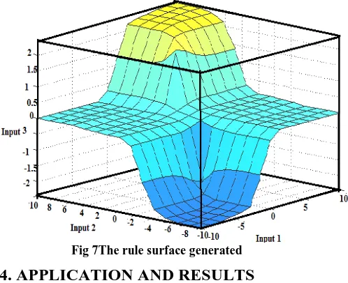
[image:4.595.316.565.384.587.2]This fuzzy membership values are used in the rule base in order to execute the related rules so that an output can be generated. A rule base consists of a data table which includes information related to the system. A fuzzy control that has thirty-five rules is realized. These rules have been utilized in designing the controller and the rules are defined in Table 2.
Table 2.The Fuzzy rule base
An inference mechanism interprets the inputs and take decisions to control the plant effectively. A defuzzification interface converts the conclusions of the inference mechanism into the crisp inputs for the process.
Fig 7The rule surface generated
4. APPLICATION AND RESULTS
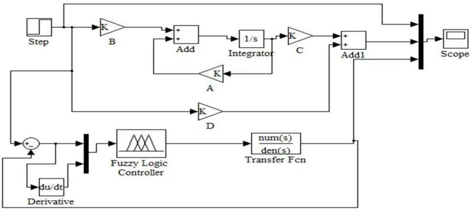
An aircraft yaw control system is simulated using LQR and FLC and the related simulation results are presented and discussed. Matlab/Simulink model block diagram of this system is shown in Fig. 11. The system response with LQR is shown in Fig 8 and that with FLC is shown in fig 9.For comparing the performance of the controllers, both the responses are plotted on the same graph. in Fig. 10.
INPUTS BN NE ZR PE BP
BN BNT NNT NNT NT ZT
N NNT NT NT ZT PT
SN NNT NT ZT ZT PT
Z NT NT ZT PT PT
SP NT NT ZT PT PT
P NT ZT ZT PT NPT
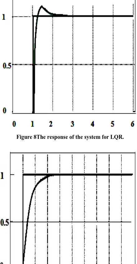
[image:4.595.58.282.605.770.2]Figure 8The response of the system for LQR.
[image:5.595.54.274.88.512.2]Figure 9. The response of the system for FLC .
Fig 10 Step response for LQR and FLC
From the responses,it is clear that the settling time of FLC is greater than that of LQR controller.LQR controller is faster than FLC,but it has a drawback of overshoot.The steady-state error of LQR controller is very much less than that of FLC,which indicates the disturbance rejection capability of LQR controller.The performance characteristics of both controllers are summarized in table 3.
Table 3.Summary of performance characteristic
Performance
Characteristic LQR FLC
Settling Time (TS)
1.1 sec 2 sec
Steady-State
Error (ess, %) 0.03 1.3
Overshoot (M,
[image:5.595.316.542.384.565.2]5. CONCLUSION
In this paper, the model of an aircraft yaw control system was designed in Matlab/Simulink environment and control methods were proposed for this system. LQR and FLC are successfully designed andresponses are verified. The results from LQR are compared with those obtained using FL controller. It was observed that both FLC and LQR have different steady-state error and overshoot.. Analysis of obtained results shows that LQR controller relatively gives the best performance in comparison to FLC and using such controller increases speed of the time response and helps in the efficient controlling of the system.
6. ACKNOWLEDGMENTS
The authors would like to express their appreciation to MrsValsalaKumari&Ms.Veena for their sensible help and honorable support.
7. REFERENCES
[1] R. C. Nelson, 1998, Flight Stability and Automatic Control, McGraw Hill, Second Edition.
[2] Lucio R. Riberio and Neusa Maria F. Oliveira, “UAV Autopilot Controllers Test Platform Using Matlab/Simulink and X-Plane”, 40th ASEE/IEEE Frontiers in Education Conference, October 27-30, 2010, Washington, DC.
[3]M. Ali Usta,ÖmürAkyazı and SefaAkpınar “Aircraft Roll Control System Using LQR and Fuzzy Logic Controller”,2011 IEEE,978-1-61284-922-5/11/26.00
[4] Nurbaiti Wahid and MohdFua’adRahmat, “Pitch Control System Using LQR and Fuzzy Controller”, 2010 IEEE Symposium on Industrial Electronics and Applications (ISIEA 2010), October 3-5, 2010, Penang, Malaysia (01.03.2011)
[5] Mıchael V. Cook, 2007, Flight Dynamics Prıncıples, Elsevıer, Second Edition.
[6]Matilde Santos, Victoria LópezFrancisoMorata, “Intelligent Fuzzy Controller of a Quadrotor”,2010 IEEE978-1-4244-6793-8/10/$26.00
[7] Le Zhang1,2, Shaojie Bi2, Hong Yang2,”Fuzzy-PID Control Algorithm of the Helicopter Model Flight Attitude Control”, 978-1-4244-5182-1/10/$26.00 _c 2010 IEEE
[8]Nurbaiti Wahid, NurhaffizahHassan,”Self-tuning Fuzzy PID Controller Design for Aircraft Pitch Control”,978-0-7695-4668-1/12 $26.00 © 2012 IEEE
[9]Zhichao Liu, ZouhairChoukri el haj, and HongboShi ,“Control Strategy Design Based on Fuzzy Logic and LQR for 3-DOFHelicopter Model”,978-1-4244-7050-1/10/$26.00 2011IEEE
[10]Joshué Pérez, Vicente Milanés, and Enrique Onieva,” Cascade Architecture for Lateral Control inAutonomous Vehicles”, IEEE TRANSACTIONS ON INTELLIGENT TRANSPORTATION SYSTEMS, VOL. 12, NO. 1, MARCH 2011
[image:6.595.55.537.97.316.2][11] www.wikipedia.org//wiki/Flight_control_system
![Figure 1.Yaw ,Roll& Pitch motion of Aircraft [10].](https://thumb-us.123doks.com/thumbv2/123dok_us/8116251.792622/1.595.324.570.484.667/figure-yaw-roll-pitch-motion-aircraft.webp)
![Figure 2. Definition of forces, moments and velocity components in a body fixed frame [1]](https://thumb-us.123doks.com/thumbv2/123dok_us/8116251.792622/2.595.62.277.66.223/figure-definition-forces-moments-velocity-components-fixed-frame.webp)